EP0203448B1 - Matching hardcopy color to display color - Google Patents
Matching hardcopy color to display color Download PDFInfo
- Publication number
- EP0203448B1 EP0203448B1 EP86106503A EP86106503A EP0203448B1 EP 0203448 B1 EP0203448 B1 EP 0203448B1 EP 86106503 A EP86106503 A EP 86106503A EP 86106503 A EP86106503 A EP 86106503A EP 0203448 B1 EP0203448 B1 EP 0203448B1
- Authority
- EP
- European Patent Office
- Prior art keywords
- color
- cmy
- data
- msw
- video display
- Prior art date
- Legal status (The legal status is an assumption and is not a legal conclusion. Google has not performed a legal analysis and makes no representation as to the accuracy of the status listed.)
- Expired - Lifetime
Links
Images


Classifications
-
- H—ELECTRICITY
- H04—ELECTRIC COMMUNICATION TECHNIQUE
- H04N—PICTORIAL COMMUNICATION, e.g. TELEVISION
- H04N1/00—Scanning, transmission or reproduction of documents or the like, e.g. facsimile transmission; Details thereof
- H04N1/46—Colour picture communication systems
- H04N1/56—Processing of colour picture signals
- H04N1/60—Colour correction or control
- H04N1/6058—Reduction of colour to a range of reproducible colours, e.g. to ink- reproducible colour gamut
Definitions
- the present invention relates to transformation of a color image from one color space to another, and more particularly to an efficient algorithm for performing the transformation of color of known composition in terms of the intensities of video red, green and blue phosphors into the necessary densities of cyan, magenta, yellow and black inks, as deposited by a display device, to yield a visual match between the color so produced on hardcopy and the video color.
- the defining data can have a number of different forms. Images taken from photographic sources exist as values in RGB, based upon a set of color separation filters which may or may not be clearly defined. Images generated originally on a graphics display exist as values in the RGB drive intensities for the set of phosphors, such as a NTSC standard phosphor set, used in creating them, the parameters of which set may or may not be known. Images generated by a computer are based on an arbitrary set of RGB definitions which may or may not be known. Thus no single set of primaries can be defined for all the needed transformations.
- a video display color is produced by adding light from the various phosphors
- a hardcopy device color is produced by subtracting light via the inks used.
- the result is that, for example, the display red is not the same as the hardcopy red.
- Fig. 1 the particular gamuts of a particular video display (phosphor set) and a particular ink and paper system are shown. The diagram shows that there are large areas of union between the two gamuts, but there are also non- neglible areas of disunion. If a color from the video gamut is not within the hardcopy gamut, i.e., unreachable, it has to be represented by a color that is within the hardcopy gamut.
- All unreachable colors may be collapsed to the closest reachable color, which throws away discriminability; the video gamut may be limited so no color is specified that cannot be matched, which is probably unacceptable; the larger gamut may be compressed into the smaller one through some sort of scaled mapping, which discards the possibility of a match entirely; or some reachable color may be substituted for any unreachable one, while endeavoring to match all reachable ones as accurately as possible.
- What is desired is a way to implement the latter choice by reducing the lightness, i.e., the normalized brightness, partly down to a point at which the chroma can be reached, and then reducing the chroma until the lowered lightness can be reached.
- the video white is normally very different in chromaticity from a white copy sheet viewed under usual room lighting. In terms of correlated color temperature the video white is likely to lie between 6500 and 9500 degrees Kelvin, while that of the sheet is easily under 4000. In visual terms the video white is quite blue relative to the white of the sheet. It is not desirable to have the white areas of an image rendered as a robins-egg blue in the copy.
- What is desired is a method for weighting the intensities of the phosphor primaries so that when combined in even levels, and evaluated with color matching functions, they yield the chromaticity coordinates of the neutrals to which they are to be matched, rather than the actual coordinates of the video white.
- a fixed relationship is established between the numeric array and addressable points. At each addressable point the fractional area coverage desired is obtained for each ink, the value is multiplied by N**2, the product is rounded, and the result is added to the array number corresponding to the particular addressable point. If the sum is greater than (N**2)-1, a dot is printed at that point, otherwise not. This results in optimum shading of the paper, in preservation of the maximum contrast edges at the full resolution of the system, and in correct location and continuity of the lower contrast edges though with increasing loss of acutance as contrast is lower. When placement has been determined for the ink dots, the resulting color is calculated by a method analogous to that used for the phosphor outputs.
- the present invention as characterized in claim 1 provides a color transformation algorithm for matching hardcopy color to display color to take account both of the limitations of video color and of the imperfect character of the colorants in the inks used.
- the video red-green- blue (RGB) is normalized and converted into chromaticity coordinates in XYZ color space.
- the hardcopy system is reduced to a well-behaved system (MSW, representing mixed, sole and white color components, as described hereinafter) which can be solved explicitly by restricting the hardcopy colors to some percentage of one of the binary mixtures of inks, some percentage of one of the single inks, and some percentage of sheet white.
- MSW well-behaved system
- Unreachable colors are mapped into reachable colors.
- Correction for hardcopy nonlinearities is accomplished by distorting the calculated ink amounts using a function derived from measurement of the dot characteristic. A coverage ratio is used to correct for color shifts. The result is cyan-magenta-yellow (CMY) values representing the hardcopy color which matches the video color. For copiers requiring an RGB input, the bits of the CMY values are complemented. The resulting color is sent to a dithering algorithm to convert these percentages into dots on paper.
- CMY cyan-magenta-yellow
- the first step in matching hardcolor copy is to convert the video RGB data from the color map of a display device into a standard C.I.E., or XYZ, space.
- a standard C.I.E. or XYZ, space.
- CIE Commission International de L'Eclairage
- X, Y, and Z have positive values.
- a triangle 14 represents the video display gamut, i.e., the colors which can be displayed by a particular three primary color system, such as the NTSC phosphor-set commonly used for color video display devices.
- An irregular polygon 16 represents the colors which can be displayed by a hardcopy device, such as an ink-jet printer with cyan-magenta-yellow (CMY) and black inks and a particular paper.
- the RGB data is in the form of n-bit words from the color map of the video display, i.e, an integer value between 0 and (2**n)-1. This data is normalized to a range of 0-1.0 with compensation for the video gamma. As is shown in Fig. 1 the hardcopy, or paper, white 18 is not the same as the video display white 20. Therefore, the video display white 20 when mapped into the XYZ color space and then converted to the hardcopy produces a greenish color.
- the conversion from RGB space to XYZ space first involves weighting the conversion matrix so that the video and hardcopy whites are coincident, i.e., unit values of RGB in video white are treated as though they produced paper white to insure that neutral colors on the video display print as neutral colors on the hardcopy/device.
- the data is converted from RGB space to XYZ space via a 3x3 matrix multiply: where the parameters of the matrix multiplier A are based upon measured data for the particular phosphor set as weighted to produce white coincidence.
- RGB space To convert from XYZ space to the hardcopy space involves eight unknowns, namely the three components of RGB space, the three components of CMY space, white and black.
- the Neugebauer equations for XYZ space are defined as:
- RGB registered-dot ink-jet hardcopy device combination colors
- the next step is to convert the XYZ color space to the MSW color space.
- RGB components There are six possible combinations of the RGB components: Based upon the relative magnitudes of red, green and blue in the video display data, an initial one of the six possible color correction matrices is selected to perform the conversion.
- each color correction matrix corresponds to some region of RGB values. For colors near the borders of these regions the initial matrix selection may be incorrect, which leads to negative values in the mixed or single components. Since a "negative" dot cannot be printed, the useful solution consists only of positive values. When a negative value occurs, the next closest matrix is selected and the XYZ to MSW conversion is performed again. Most of the time the initial matrix yields all positive values for the mixed and single components. Using the all positive result black is determined by the difference between a unit area and the mixed, single and white areas:
- XYZ space Since the conversion from XYZ space to MSW space involves a 3x3 matrix multiplication, and the conversion from RGB space to XYZ space also involves a 3x3 matrix multiplication, a direct conversion from KGB space to MSW space may be used: However, since both RGB space and MSW space are referenced to a common XYZ space, the XYZ space serves to isolate the video color world from the hardcopy color world. Also, as is discussed infra, XYZ space is used to restore any differentiation that may be lost.
- the white component of MSW space is negative, the requested color is too saturated and cannot be reproduced on the hardcopy.
- the negative white values are set equal to zero. This is equivalent to an unreachable color 22 which exists within the video color gamut 14, but outside the hardcopy color gamut 16.
- the zeroing of the white acts to pull the color in along a line 24 connecting the hardcopy white 18 to the unreachable video color 22 until the perimeter 26 of the hardcopy color gamut 16 is attained.
- This line 24 is called the dominant wavelength of the color, and the dominant wavelength of the color is maintained while its saturation is decreased.
- MSW components [M', S', W',] are summed. If the sum exceeds 1.0, the requested color is brighter than the hardcopy device can achieve under the illuminant selected. In this situation the components are normalized by dividing each component by the sum, making the sum of the components less than 1.0. Now the resulting MSW components [M",S",W”] is a reachable color for the hardcopy device. However, because of the above compensations for the unreachable colors, colors which are different in color or brightness on the video display are matched as the same color on the hardcopy device.
- the next step is to restore the shading or edge between adjacent colors, i.e., the distinction between adjacent colors.
- Black is the remainder when MSW components are subtracted from 1.0, generally given as follows: wherein for this specific case W t by definition is zero since white was negative. This has the effect of adding black ink to pull the brightness down. If Y' is less than Y, resulting from the component sum being greater than 1.0, white is added by calculating a scale factor, based upon the difference between Y and Y', to be applied to the mixed and single components. The white component is then set equal to the remaining area after the mixed and single component is subtracted out: While the previous two steps, equations (10) and (11), preserve the luminance differences between unreachable colors at the expense of chromaticity matches, this step increases the luminance of the color while decreasing its saturation.
- the final MSW vector has components which match the color exactly where the video and hardcopy gamuts are coincident, which match the color to a reachable color if the color is within the video gamut but outside the hardcopy gamut, and which match the color into colors which preserve the difference between colors.
- the next step is to determine what inks to put down on the paper, i.e., convert the MSW components into CMY components. The assignment of values for the inks depends upon the particular MSW conversion matrix used. One of the inks, the single component such as the cyan (C) shown in equations (3), appears everywhere ink is laid down. The value of this ink is: A second ink occurs in both the mixed component and black and has a value: where B t is the black.
- the mixture of C max + C mid produces the mixed component shown as green (G) in equations (3).
- the third ink appears only in the black:
- the CMY values, C max , C mid and Cmin represent the percentages of each ink to be used for a given color for a registered-dot ink-jet hardcopy device, i.e., where the mixed and black components are formed by overlaying dots of ink on top of each other.
- CMY percentages do not represent a uniformly applied amount of ink with variable optical density, but rather the fraction of discrete drops to be deposited over some area of the paper.
- the correct color sensation is produced because the visual system averages this pattern of dots. Because the ink dots overlap, this visual sensation is not linear with the number of dots in the pattern.
- the CMY values are used as indices to hardcopy gamma correction lookup tables, based upon measurements containing new values which compensate for the system irregularities. Since black is usually a separate ink rather than a combination of the three color inks, a black gamma correction table is used to compensate for Cmin.
- C mid two difficulties arise.
- C max and C mid are combined, the amount of dot overlap is different due to the wetting of the paper surface by the first ink laid down. This results in a gamma correction characteristic of the binary mixture which differs from the gamma correction characteristics for the individual inks. Therefore, C mid is processed using a mixture gamma correction table (red, green or blue) rather than a single ink gamma correction table.
- the prior gamma correction of C min leads to noticeable shifts since after gamma correction through their respective tables the percentage coverage of C mid by C min changes.
- a coverage ratio is computed from the original, uncorrected values as:
- the gamma corrected value of C min is then used as an index to the inverse of the C mid gamma correction table to yield a base value.
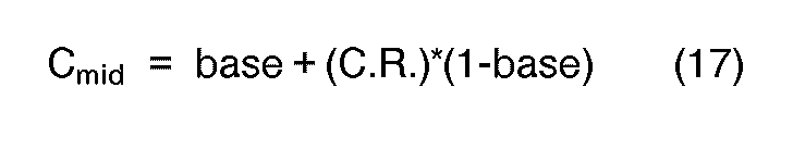
- a corrected value for C mid is then computed as:
- C m i d and Cmax Where base' is determined by inverse gamma transformation of gamma-corrected C mid through the appropriate CMY (single color) gamma-correction table. C max ' is then gamma corrected through the appropriate CMY table. This produces a new CMY vector [C',M',Y'] which may be output to a hardcopy device, or complemented to determine a new RGB vector [R',G',B'] for those devices which require an RGB input. The output of the color matching algorithm is then processed by an appropriate dithering algorithm to convert the resulting color data into drops of ink on the paper.
- the present invention provides a method for matching hardcopy color to video color by replacing video RGB with hardcopy RGB which compensates for the effects of video gamma, paper, and ink by use of a new MSW space, and which compensates for the ink-jet gamma by appropriately chosed gamma correction tables together with using a coverage ratio for interaction of the inks.
Landscapes
- Engineering & Computer Science (AREA)
- Multimedia (AREA)
- Signal Processing (AREA)
- Facsimile Image Signal Circuits (AREA)
- Color Image Communication Systems (AREA)
- Image Processing (AREA)
- Ink Jet (AREA)
- Processing Of Color Television Signals (AREA)
Description
- The present invention relates to transformation of a color image from one color space to another, and more particularly to an efficient algorithm for performing the transformation of color of known composition in terms of the intensities of video red, green and blue phosphors into the necessary densities of cyan, magenta, yellow and black inks, as deposited by a display device, to yield a visual match between the color so produced on hardcopy and the video color.
- There are situations where a hardcopy of a color video display should match that display in color. Two examples are renderings of digitized photographs and proofing copies for a graphic artist's work station, and it is considered by people working in hardcopy technology that a color match is desirable generally.
- The defining data can have a number of different forms. Images taken from photographic sources exist as values in RGB, based upon a set of color separation filters which may or may not be clearly defined. Images generated originally on a graphics display exist as values in the RGB drive intensities for the set of phosphors, such as a NTSC standard phosphor set, used in creating them, the parameters of which set may or may not be known. Images generated by a computer are based on an arbitrary set of RGB definitions which may or may not be known. Thus no single set of primaries can be defined for all the needed transformations.
- For a video display color is produced by adding light from the various phosphors, while for a hardcopy device color is produced by subtracting light via the inks used. The result is that, for example, the display red is not the same as the hardcopy red. In Fig. 1 the particular gamuts of a particular video display (phosphor set) and a particular ink and paper system are shown. The diagram shows that there are large areas of union between the two gamuts, but there are also non- neglible areas of disunion. If a color from the video gamut is not within the hardcopy gamut, i.e., unreachable, it has to be represented by a color that is within the hardcopy gamut. All unreachable colors may be collapsed to the closest reachable color, which throws away discriminability; the video gamut may be limited so no color is specified that cannot be matched, which is probably unacceptable; the larger gamut may be compressed into the smaller one through some sort of scaled mapping, which discards the possibility of a match entirely; or some reachable color may be substituted for any unreachable one, while endeavoring to match all reachable ones as accurately as possible. What is desired is a way to implement the latter choice by reducing the lightness, i.e., the normalized brightness, partly down to a point at which the chroma can be reached, and then reducing the chroma until the lowered lightness can be reached.
- However, even if the primary colors are matched, the whites are not. The video white is normally very different in chromaticity from a white copy sheet viewed under usual room lighting. In terms of correlated color temperature the video white is likely to lie between 6500 and 9500 degrees Kelvin, while that of the sheet is easily under 4000. In visual terms the video white is quite blue relative to the white of the sheet. It is not desirable to have the white areas of an image rendered as a robins-egg blue in the copy.
- There is a phenomenon that has relevance to the above problem: if a person looks at a colored picture under bright, indirect sunlight, and then at the same picture under only incandescent lighting, the correlated color temperature change in the light sources is from 6500 degrees down to 2600 degrees. The white areas in the picture do not look robins-egg blue outdoors, nor do they look canary yellow indoors, although that is approximately the magnitude of the colorimetric change in those areas for the two conditions. This phenomenon is akin to color constancy, i.e., over a broad range a person continuously redefines white as some kind of average over all areas in view.
- What is desired is a method for weighting the intensities of the phosphor primaries so that when combined in even levels, and evaluated with color matching functions, they yield the chromaticity coordinates of the neutrals to which they are to be matched, rather than the actual coordinates of the video white.
- With respect to the hardcopy device, present ink-jets do not afford control of dot size. Thus halftoning, used to produce color in the printing industry, cannot be done with ink-jets. Fractional area coverage, for a particular ink, is only achieved by defining some number of addressable points, normally a square array, and then determining at how many of them to place a dot. This is done by developing a square array of numbers with the same number, N, of elements per side as the array of addressable points to be used. The array of numbers contains every number from 0 to (N**2)-1, and the numbers are positioned in the array so that as the pattern is filled the dots on paper are as uniformly distributed as possible.
- A fixed relationship is established between the numeric array and addressable points. At each addressable point the fractional area coverage desired is obtained for each ink, the value is multiplied by N**2, the product is rounded, and the result is added to the array number corresponding to the particular addressable point. If the sum is greater than (N**2)-1, a dot is printed at that point, otherwise not. This results in optimum shading of the paper, in preservation of the maximum contrast edges at the full resolution of the system, and in correct location and continuity of the lower contrast edges though with increasing loss of acutance as contrast is lower. When placement has been determined for the ink dots, the resulting color is calculated by a method analogous to that used for the phosphor outputs. The contributions for each surface color are weighted by the fractional area it covers since there is no variation in intensity. However, the ink dots cover more than the addressable points, and therefore there is more color than desired. This implies that a correction for oversized dots must be performed to get a good color match.
- Accordingly, the present invention as characterized in
claim 1 provides a color transformation algorithm for matching hardcopy color to display color to take account both of the limitations of video color and of the imperfect character of the colorants in the inks used. The video red-green- blue (RGB) is normalized and converted into chromaticity coordinates in XYZ color space. The hardcopy system is reduced to a well-behaved system (MSW, representing mixed, sole and white color components, as described hereinafter) which can be solved explicitly by restricting the hardcopy colors to some percentage of one of the binary mixtures of inks, some percentage of one of the single inks, and some percentage of sheet white. The data in XYZ color space is converted to this MSW space. Unreachable colors are mapped into reachable colors. Correction for hardcopy nonlinearities is accomplished by distorting the calculated ink amounts using a function derived from measurement of the dot characteristic. A coverage ratio is used to correct for color shifts. The result is cyan-magenta-yellow (CMY) values representing the hardcopy color which matches the video color. For copiers requiring an RGB input, the bits of the CMY values are complemented. The resulting color is sent to a dithering algorithm to convert these percentages into dots on paper. - The objects, advantages and novel features of the present invention will be apparent from the following detailed description when read in conjunction with the appended claims and attached drawing.
- Fig. 1 is a plot of the comparison of a video diplay gamut and a hardcopy gamut in a CIE (XYZ) chromaticity space.
- Fig. 2 is a flow chart showing the sequence of events for matching video color and hardcopy color.
- Figs. 3a and 3b are a block diagram flow chart for matching video color and hardcopy color corresponding to Fig. 2.
- Referring now to Figs. 2, 3A and 3B, the first step in matching hardcolor copy is to convert the video RGB data from the color map of a display device into a standard C.I.E., or XYZ, space. To define a given color using three primary colors, such as red, green, blue, the value of one of the primaries may be negative. The Commission International de L'Eclairage (CIE), or International Commission on Illumination, in 1931 defined a transformation so that in a new color coordinate system all the components, X, Y, and Z have positive values. The C.I.E. diagram, as shown in Fig. 1 is a generally horseshoe-
shaped spectrum locus 12 in a plane Cartesian XY coordinate system on which points representing the chromaticities of the spectrum colors are plotted according to their wavelengths in nanometers. The Z-axis, orthogonal to the XY plane, determines the luminance of the color. Atriangle 14 represents the video display gamut, i.e., the colors which can be displayed by a particular three primary color system, such as the NTSC phosphor-set commonly used for color video display devices. Anirregular polygon 16 represents the colors which can be displayed by a hardcopy device, such as an ink-jet printer with cyan-magenta-yellow (CMY) and black inks and a particular paper. - The RGB data is in the form of n-bit words from the color map of the video display, i.e, an integer value between 0 and (2**n)-1. This data is normalized to a range of 0-1.0 with compensation for the video gamma. As is shown in Fig. 1 the hardcopy, or paper, white 18 is not the same as the video display white 20. Therefore, the video display white 20 when mapped into the XYZ color space and then converted to the hardcopy produces a greenish color. Thus, the conversion from RGB space to XYZ space first involves weighting the conversion matrix so that the video and hardcopy whites are coincident, i.e., unit values of RGB in video white are treated as though they produced paper white to insure that neutral colors on the video display print as neutral colors on the hardcopy/device. Now the data is converted from RGB space to XYZ space via a 3x3 matrix multiply:

- To convert from XYZ space to the hardcopy space involves eight unknowns, namely the three components of RGB space, the three components of CMY space, white and black. The Neugebauer equations for XYZ space are defined as:


- The next step is to convert the XYZ color space to the MSW color space. There are six possible combinations of the RGB components:


- Since the conversion from XYZ space to MSW space involves a 3x3 matrix multiplication,


- If the white component of MSW space is negative, the requested color is too saturated and cannot be reproduced on the hardcopy. The negative white values are set equal to zero. This is equivalent to an
unreachable color 22 which exists within thevideo color gamut 14, but outside thehardcopy color gamut 16. The zeroing of the white acts to pull the color in along aline 24 connecting the hardcopy white 18 to theunreachable video color 22 until theperimeter 26 of thehardcopy color gamut 16 is attained. Thisline 24 is called the dominant wavelength of the color, and the dominant wavelength of the color is maintained while its saturation is decreased. - After all negative values have been corrected, the corrected, or compensated, MSW components [M', S', W',] are summed. If the sum exceeds 1.0, the requested color is brighter than the hardcopy device can achieve under the illuminant selected. In this situation the components are normalized by dividing each component by the sum, making the sum of the components less than 1.0. Now the resulting MSW components [M",S",W"] is a reachable color for the hardcopy device. However, because of the above compensations for the unreachable colors, colors which are different in color or brightness on the video display are matched as the same color on the hardcopy device.
- Therefore, the next step is to restore the shading or edge between adjacent colors, i.e., the distinction between adjacent colors. This is accomplished by calculating a new Y component for the MSW space by using the inverse matrix of the XYZ to MSW conversion matrix:


- These CMY percentages do not represent a uniformly applied amount of ink with variable optical density, but rather the fraction of discrete drops to be deposited over some area of the paper. The correct color sensation is produced because the visual system averages this pattern of dots. Because the ink dots overlap, this visual sensation is not linear with the number of dots in the pattern. To handle this irregularity the CMY values are used as indices to hardcopy gamma correction lookup tables, based upon measurements containing new values which compensate for the system irregularities. Since black is usually a separate ink rather than a combination of the three color inks, a black gamma correction table is used to compensate for Cmin.
- For Cmid two difficulties arise. First, when Cmax and Cmid are combined, the amount of dot overlap is different due to the wetting of the paper surface by the first ink laid down. This results in a gamma correction characteristic of the binary mixture which differs from the gamma correction characteristics for the individual inks. Therefore, Cmid is processed using a mixture gamma correction table (red, green or blue) rather than a single ink gamma correction table. Second, the prior gamma correction of Cmin leads to noticeable shifts since after gamma correction through their respective tables the percentage coverage of Cmid by Cmin changes. To avoid this problem a coverage ratio is computed from the original, uncorrected values as:

- As an example, if the value for Cmid is 1/2 and for Cmin is 1/4, then 50% of the Cmid covers Cmin. Then if the gamma correction is Cmid = 3/8 andCmin = 1/8, now only 33% of the Cmid covers Cmin resulting in more color than desired. The color ratio serves to restore the appropriate ratio after gamma correction.
- Likewise for Cmid and Cmax:


- Thus, the present invention provides a method for matching hardcopy color to video color by replacing video RGB with hardcopy RGB which compensates for the effects of video gamma, paper, and ink by use of a new MSW space, and which compensates for the ink-jet gamma by appropriately chosed gamma correction tables together with using a coverage ratio for interaction of the inks.
Claims (5)
Applications Claiming Priority (2)
| Application Number | Priority Date | Filing Date | Title |
|---|---|---|---|
| US737765 | 1985-05-28 | ||
| US06/737,765 US4670780A (en) | 1985-05-28 | 1985-05-28 | Method of matching hardcopy colors to video display colors in which unreachable video display colors are converted into reachable hardcopy colors in a mixture-single-white (MSW) color space |
Publications (3)
| Publication Number | Publication Date |
|---|---|
| EP0203448A2 EP0203448A2 (en) | 1986-12-03 |
| EP0203448A3 EP0203448A3 (en) | 1989-03-08 |
| EP0203448B1 true EP0203448B1 (en) | 1993-01-13 |
Family
ID=24965224
Family Applications (1)
| Application Number | Title | Priority Date | Filing Date |
|---|---|---|---|
| EP86106503A Expired - Lifetime EP0203448B1 (en) | 1985-05-28 | 1986-05-13 | Matching hardcopy color to display color |
Country Status (6)
| Country | Link |
|---|---|
| US (1) | US4670780A (en) |
| EP (1) | EP0203448B1 (en) |
| JP (1) | JPS61277267A (en) |
| CN (1) | CN1005522B (en) |
| CA (1) | CA1262286A (en) |
| DE (1) | DE3687476T2 (en) |
Cited By (1)
| Publication number | Priority date | Publication date | Assignee | Title |
|---|---|---|---|---|
| US9219898B2 (en) | 2005-12-21 | 2015-12-22 | Thomson Licensing | Constrained color palette in a color space |
Families Citing this family (68)
| Publication number | Priority date | Publication date | Assignee | Title |
|---|---|---|---|---|
| US4796086A (en) * | 1984-11-30 | 1989-01-03 | Fuji Photo Film Co., Ltd. | Method for converting color picture signals |
| US4731662A (en) * | 1985-03-21 | 1988-03-15 | Canon Kabushiki Kaisha | Image processing method for processing an image signal differently depending on the range of an image characteristic thereof relative to the range within which an output device can reproduce the image characteristic |
| GB8516232D0 (en) * | 1985-06-27 | 1985-07-31 | Crosfield Electronics Ltd | Colour displays |
| GB8622564D0 (en) * | 1986-09-19 | 1986-10-22 | Crosfield Electronics Ltd | Reproduction of coloured images |
| US4751535A (en) * | 1986-10-15 | 1988-06-14 | Xerox Corporation | Color-matched printing |
| EP0273398B1 (en) * | 1986-12-25 | 1995-02-08 | Konica Corporation | Method of correcting color images |
| US4941038A (en) * | 1987-05-11 | 1990-07-10 | The Mead Corporation | Method for color image processing |
| US4843573A (en) * | 1987-10-26 | 1989-06-27 | Tektronix, Inc. | Display-based color system |
| US4985853A (en) * | 1987-10-26 | 1991-01-15 | Tektronix, Inc. | Display-based color system |
| DE3738014A1 (en) * | 1987-11-09 | 1989-05-18 | Winrich Dipl Ing Gall | Method of generating coloured images on a carrier surface |
| JP2678007B2 (en) * | 1988-03-08 | 1997-11-17 | 株式会社リコー | Color information correction device |
| US4884130A (en) * | 1988-04-29 | 1989-11-28 | Minnesota Mining And Manufacturing Company | Method of describing a color in a triaxial planar vector color space |
| EP0351188B1 (en) * | 1988-07-12 | 1993-10-06 | Niigata Prefecture | Method of transforming the light-source color data and the non-luminous object color data |
| US4945406A (en) * | 1988-11-07 | 1990-07-31 | Eastman Kodak Company | Apparatus and accompanying methods for achieving automatic color balancing in a film to video transfer system |
| US4994901A (en) * | 1988-12-23 | 1991-02-19 | Eastman Kodak Company | Method and apparatus for increasing the gamut of an additive display driven from a digital source |
| EP0454275B1 (en) * | 1990-04-26 | 1996-07-03 | Bayer Corporation | Color separation method |
| US5282046A (en) * | 1990-07-25 | 1994-01-25 | Brother Kogyo Kabushiki Kaisha | Color image forming apparatus having a color-correcting unit |
| US5157506A (en) * | 1990-08-29 | 1992-10-20 | Savitar, Inc. | Standardized color calibration of electronic imagery |
| US5237517A (en) * | 1990-08-29 | 1993-08-17 | Xerox Corporation | Color printing having a highlight color image mapped from a full color image |
| US5237409A (en) * | 1990-09-10 | 1993-08-17 | Brother Kogyo Kabushiki Kaisha | Color image forming apparatus using color compressed color data |
| US5172224A (en) * | 1990-12-18 | 1992-12-15 | Eastman Kodak Company | Printer calibration method using electronically-decoupled color and tone scale adjustments |
| BE1004659A5 (en) * | 1991-03-01 | 1993-01-05 | Barco Graphics Nv | METHOD AND APPARATUS FOR transforming a KLEURCOORDINATENSET. |
| EP0523898B1 (en) * | 1991-07-08 | 1999-05-06 | Canon Kabushiki Kaisha | Color expressing method, color image reading apparatus and color image processing apparatus |
| US5243414A (en) * | 1991-07-29 | 1993-09-07 | Tektronix, Inc. | Color processing system |
| US5313291A (en) * | 1991-11-25 | 1994-05-17 | Xerox Corporation | Method for matching color prints to color images on a monitor screen |
| US5319473A (en) * | 1991-11-27 | 1994-06-07 | Xerox Corporation | Methods and apparatus for performing real time color gamut compressions |
| US5231504A (en) * | 1991-12-30 | 1993-07-27 | Xerox Corporation | Method for improved color reproduction using linear mixing calculations based on positional relationships between an original color and an achromatic region in a linear mixing space |
| US5309257A (en) * | 1991-12-31 | 1994-05-03 | Eastman Kodak Company | Method and apparatus for providing color matching between color output devices |
| AU656057B2 (en) * | 1992-03-27 | 1995-01-19 | Milliken & Company | Method and apparatus for reproducing blended colorants on an electronic display |
| JPH05336287A (en) * | 1992-05-30 | 1993-12-17 | Minolta Camera Co Ltd | Image forming device |
| US5481655A (en) * | 1992-09-18 | 1996-01-02 | Iris Graphics, Inc. | System for matching a picture on a monitor to a printed picture |
| US5748195A (en) * | 1992-10-29 | 1998-05-05 | International Business Machines Corporation | Method and means for evaluating a tetrahedral linear interpolation function |
| US5432892A (en) * | 1992-11-25 | 1995-07-11 | International Business Machines Corporation | Volummetric linear interpolation |
| EP0604755B1 (en) * | 1992-12-15 | 1999-05-12 | E.I. Du Pont De Nemours And Company | Color matching method and apparatus |
| US5390035A (en) * | 1992-12-23 | 1995-02-14 | International Business Machines Corporation | Method and means for tetrahedron/octahedron packing and tetrahedron extraction for function approximation |
| US5751926A (en) * | 1992-12-23 | 1998-05-12 | International Business Machines Corporation | Function approximation using a centered cubic packing with tetragonal disphenoid extraction |
| DE69413575T2 (en) * | 1993-02-12 | 1999-05-20 | Eastman Kodak Co., Rochester, N.Y. | Method and device for transforming input color sizes into an input color space into output color sizes into an output color space |
| US5677967A (en) * | 1993-03-10 | 1997-10-14 | R. R. Donnelley & Sons Company | Method of and apparatus for converting between a color appearance space and a colorant space |
| DE4409226C2 (en) * | 1993-04-08 | 1998-04-30 | Hell Ag Linotype | Process and device for the transformation of color bodies |
| US5696839A (en) * | 1993-04-08 | 1997-12-09 | Linotype-Hell Ag | Method and apparatus for reproducing an image employing a transformation of color solids |
| US5508826A (en) * | 1993-04-27 | 1996-04-16 | Lloyd; William J. | Method and apparatus for calibrated digital printing using a four by four transformation matrix |
| DE4334712A1 (en) * | 1993-10-12 | 1995-04-13 | Heidelberger Druckmasch Ag | Reproduction system |
| DE4404557A1 (en) * | 1994-02-12 | 1995-08-17 | Heidelberger Druckmasch Ag | Colour ink jet printing appts |
| US5557712A (en) * | 1994-02-16 | 1996-09-17 | Apple Computer, Inc. | Color map tables smoothing in a color computer graphics system avoiding objectionable color shifts |
| JP3745368B2 (en) * | 1994-02-16 | 2006-02-15 | アップル コンピュータ, インコーポレイテッド | Subjectively comfortable color gamut mapping in color computer graphic systems |
| JP3083067B2 (en) * | 1994-08-03 | 2000-09-04 | 富士ゼロックス株式会社 | Method and apparatus for determining color conversion coefficient |
| US5450216A (en) * | 1994-08-12 | 1995-09-12 | International Business Machines Corporation | Color image gamut-mapping system with chroma enhancement at human-insensitive spatial frequencies |
| US6108008A (en) * | 1994-09-22 | 2000-08-22 | Canon Kabushiki Kaisha | Color image mapping within output device reproduction range |
| US5572632A (en) * | 1994-10-07 | 1996-11-05 | Laser Master Corporation | Universal frame buffer for a rendering device |
| US5710577A (en) * | 1994-10-07 | 1998-01-20 | Lasermaster Corporation | Pixel description packet for a rendering device |
| US5563724A (en) * | 1994-10-21 | 1996-10-08 | Eastman Kodak Company | Color-to-ink transformation for extra-quarternary printing processes |
| US5563717A (en) * | 1995-02-03 | 1996-10-08 | Eastman Kodak Company | Method and means for calibration of photographic media using pre-exposed miniature images |
| US6137494A (en) * | 1995-08-18 | 2000-10-24 | International Business Machines Corporation | Method and means for evaluating a tetrahedral linear interpolation function |
| US5818613A (en) * | 1995-12-04 | 1998-10-06 | Silicon Graphics, Inc. | System and method for color space conversion |
| US5946113A (en) * | 1996-03-29 | 1999-08-31 | Silicon Graphics, Inc. | System and method for color space conversion |
| US6185013B1 (en) * | 1996-12-23 | 2001-02-06 | Xerox Corporation | Color printing having a plural highlight color image map in a full color image |
| US5920358A (en) * | 1997-01-30 | 1999-07-06 | Fuji Photo Film Co., Ltd. | Method of transforming colors of image |
| US6594387B1 (en) * | 1999-04-30 | 2003-07-15 | Texas Instruments Incorporated | Enhanced color correction |
| US6559975B1 (en) * | 1999-06-15 | 2003-05-06 | Microsoft Corporation | Full-color to a spot-color image converter |
| US6775028B1 (en) | 2000-02-24 | 2004-08-10 | Lexmark International, Inc. | Non-linear method of mapping the lightness and chroma of a display device gamut onto a printing device gamut |
| BR0318558A (en) * | 2003-10-22 | 2006-10-10 | Avantone Oy | method of a color diffractive system, color diffractive system, diffractive component, and product containing one or more diffractionally produced color effects |
| US7379207B2 (en) * | 2004-01-14 | 2008-05-27 | Xerox Corporation | Method and system for device-independent color gamut mapping |
| JP2006086935A (en) * | 2004-09-17 | 2006-03-30 | Canon Inc | Color processing apparatus and method, image processing method, and printer driver |
| WO2006050305A1 (en) * | 2004-11-01 | 2006-05-11 | Technicolor Inc | Method and system for mastering and distributing enhanced color space content |
| US8861023B2 (en) * | 2011-02-09 | 2014-10-14 | Xerox Corporation | Generating an unambiguous definition of designer intended colors in a document creation application |
| CN103854294B (en) * | 2012-12-06 | 2018-05-22 | 北京大学 | A kind of automatic spot color separating method and system of printed matter based on colour cast analysis |
| WO2018199882A1 (en) | 2017-04-24 | 2018-11-01 | Hewlett-Packard Development Company, L.P. | Transforming a color space vector into a neugebauer primary area coverage vector |
| CN111976325B (en) * | 2020-08-18 | 2023-01-20 | 杭州僖磊科技发展有限公司 | Traceable printing method and traceable printing system |
Family Cites Families (19)
| Publication number | Priority date | Publication date | Assignee | Title |
|---|---|---|---|---|
| JPS6035661B2 (en) * | 1975-09-12 | 1985-08-15 | 大日本スクリーン製造株式会社 | Color correction method |
| DE2844158C3 (en) * | 1978-10-10 | 1981-10-15 | Burda Verwaltungs Kg Schutterwald, 7600 Offenburg | Process for the reproduction of original documents which are scanned for their color content according to a three-range process |
| JPS561039A (en) * | 1979-06-18 | 1981-01-08 | Fuji Photo Film Co Ltd | Normalized circuit |
| DE3024459A1 (en) * | 1979-07-03 | 1981-01-08 | Crosfield Electronics Ltd | PYRAMID INTERPOLATION |
| US4425417A (en) * | 1979-09-17 | 1984-01-10 | Ingalls Marjorie D | Method for preparation of a color proof from a set of color separation films, masks or the like |
| JPS56162751A (en) * | 1980-05-20 | 1981-12-14 | Dainippon Printing Co Ltd | Printing color simulating device |
| EP0054313B1 (en) * | 1980-12-17 | 1989-11-15 | Matsushita Research Institute Tokyo, Inc. | Colour image duplicating device and method |
| DE3109190C2 (en) * | 1981-03-11 | 1985-07-11 | Dr.-Ing. Rudolf Hell Gmbh, 2300 Kiel | Process for the reproduction of colored originals in four-color printing with color removal |
| DE3276728D1 (en) * | 1981-04-07 | 1987-08-13 | Toppan Printing Co Ltd | Method and apparatus for correcting video signals in colour printing simulation |
| US4477833A (en) * | 1981-08-12 | 1984-10-16 | R. R. Donnelley & Sons Company | Method of color conversion with improved interpolation |
| JPH0716234B2 (en) * | 1981-09-01 | 1995-02-22 | キヤノン株式会社 | Color printer |
| JPS5846341A (en) * | 1981-09-16 | 1983-03-17 | Dainippon Screen Mfg Co Ltd | Converting method for reproduced color in displaying of reproduced color of multicolor printed matter |
| JPS58219867A (en) * | 1982-06-14 | 1983-12-21 | Canon Inc | Color reproduction method |
| US4481532A (en) * | 1982-06-28 | 1984-11-06 | R. R. Donnelley & Sons Company | Method of determining and storing color printing information |
| JPS5967781A (en) * | 1982-10-12 | 1984-04-17 | Canon Inc | Signal converter |
| DE3271077D1 (en) * | 1982-10-22 | 1986-06-12 | Hell Rudolf Dr Ing Gmbh | Method and apparatus for producing colour extractions for separate colour printing |
| JPS59163972A (en) * | 1983-03-08 | 1984-09-17 | Canon Inc | Color recording system |
| DE3320141C2 (en) * | 1983-06-03 | 1986-07-03 | Harald 6070 Langen Küppers | Reproduction process for making multicolored prints |
| JP3106103B2 (en) * | 1996-06-14 | 2000-11-06 | 美津濃株式会社 | Golf club head |
-
1985
- 1985-05-28 US US06/737,765 patent/US4670780A/en not_active Expired - Lifetime
-
1986
- 1986-04-25 CN CN86102826.0A patent/CN1005522B/en not_active Expired
- 1986-05-01 CA CA000508140A patent/CA1262286A/en not_active Expired
- 1986-05-13 EP EP86106503A patent/EP0203448B1/en not_active Expired - Lifetime
- 1986-05-13 DE DE8686106503T patent/DE3687476T2/en not_active Expired - Fee Related
- 1986-05-27 JP JP61122061A patent/JPS61277267A/en active Pending
Cited By (1)
| Publication number | Priority date | Publication date | Assignee | Title |
|---|---|---|---|---|
| US9219898B2 (en) | 2005-12-21 | 2015-12-22 | Thomson Licensing | Constrained color palette in a color space |
Also Published As
| Publication number | Publication date |
|---|---|
| EP0203448A3 (en) | 1989-03-08 |
| DE3687476T2 (en) | 1993-04-29 |
| EP0203448A2 (en) | 1986-12-03 |
| US4670780A (en) | 1987-06-02 |
| JPS61277267A (en) | 1986-12-08 |
| CN86102826A (en) | 1986-11-26 |
| CA1262286A (en) | 1989-10-10 |
| CN1005522B (en) | 1989-10-18 |
| DE3687476D1 (en) | 1993-02-25 |
Similar Documents
| Publication | Publication Date | Title |
|---|---|---|
| US4670780A (en) | Method of matching hardcopy colors to video display colors in which unreachable video display colors are converted into reachable hardcopy colors in a mixture-single-white (MSW) color space | |
| Hill et al. | Comparative analysis of the quantization of color spaces on the basis of the CIELAB color-difference formula | |
| US5481655A (en) | System for matching a picture on a monitor to a printed picture | |
| US7729014B2 (en) | Systems for gray component replacement blending | |
| US4992862A (en) | Color conversion display apparatus and method | |
| EP0990344B1 (en) | Gamut correction with color separation and methods and apparatuses for performing same | |
| JP3143508B2 (en) | Image processing method and apparatus | |
| US20050185200A1 (en) | Systems, methods, and computer program products for converting between color gamuts associated with different image processing devices | |
| US5657137A (en) | Color digital halftoning using black and secondary color replacement | |
| US20090040564A1 (en) | Vision-Based Color and Neutral-Tone Management | |
| EP0488656A2 (en) | Colour transformation method | |
| WO1999010835A1 (en) | Scanner calibration and correction techniques using scaled lightness values | |
| EP0980628A1 (en) | Arrangement for high-accuracy colorimetric characterization of display devices and method therefor | |
| US5920358A (en) | Method of transforming colors of image | |
| JPH09135316A (en) | Image processing apparatus and method | |
| KR100881028B1 (en) | Gray data correction device and method | |
| US20070171441A1 (en) | Color and darkness management system | |
| US20070171442A1 (en) | Color and neutral tone management system | |
| JP3792836B2 (en) | Intermediate representation of color space | |
| JP2534307B2 (en) | Color conversion device | |
| Bala | What is the Chrominance of “Gray”? | |
| Kasson | Efficient, Chromaticity-Preserving Midtone Correction for RGB Images | |
| Green | Modifying CIECAM97s surround parameters for complex images in graphic arts viewing conditions | |
| Green et al. | Surround–the New Background? | |
| JPH1198368A (en) | Color image processing equipment |
Legal Events
| Date | Code | Title | Description |
|---|---|---|---|
| PUAI | Public reference made under article 153(3) epc to a published international application that has entered the european phase |
Free format text: ORIGINAL CODE: 0009012 |
|
| AK | Designated contracting states |
Kind code of ref document: A2 Designated state(s): DE FR GB NL |
|
| PUAL | Search report despatched |
Free format text: ORIGINAL CODE: 0009013 |
|
| AK | Designated contracting states |
Kind code of ref document: A3 Designated state(s): DE FR GB NL |
|
| 17P | Request for examination filed |
Effective date: 19890721 |
|
| 17Q | First examination report despatched |
Effective date: 19910726 |
|
| RAP1 | Party data changed (applicant data changed or rights of an application transferred) |
Owner name: TEKTRONIX, INC. |
|
| GRAA | (expected) grant |
Free format text: ORIGINAL CODE: 0009210 |
|
| AK | Designated contracting states |
Kind code of ref document: B1 Designated state(s): DE FR GB NL |
|
| ET | Fr: translation filed | ||
| REF | Corresponds to: |
Ref document number: 3687476 Country of ref document: DE Date of ref document: 19930225 |
|
| PLBE | No opposition filed within time limit |
Free format text: ORIGINAL CODE: 0009261 |
|
| STAA | Information on the status of an ep patent application or granted ep patent |
Free format text: STATUS: NO OPPOSITION FILED WITHIN TIME LIMIT |
|
| 26N | No opposition filed | ||
| PGFP | Annual fee paid to national office [announced via postgrant information from national office to epo] |
Ref country code: FR Payment date: 19970411 Year of fee payment: 12 |
|
| PGFP | Annual fee paid to national office [announced via postgrant information from national office to epo] |
Ref country code: GB Payment date: 19970417 Year of fee payment: 12 |
|
| PGFP | Annual fee paid to national office [announced via postgrant information from national office to epo] |
Ref country code: DE Payment date: 19970423 Year of fee payment: 12 |
|
| PGFP | Annual fee paid to national office [announced via postgrant information from national office to epo] |
Ref country code: NL Payment date: 19970428 Year of fee payment: 12 |
|
| PG25 | Lapsed in a contracting state [announced via postgrant information from national office to epo] |
Ref country code: GB Free format text: LAPSE BECAUSE OF NON-PAYMENT OF DUE FEES Effective date: 19980513 |
|
| PG25 | Lapsed in a contracting state [announced via postgrant information from national office to epo] |
Ref country code: FR Free format text: LAPSE BECAUSE OF NON-PAYMENT OF DUE FEES Effective date: 19980531 |
|
| PG25 | Lapsed in a contracting state [announced via postgrant information from national office to epo] |
Ref country code: NL Free format text: LAPSE BECAUSE OF NON-PAYMENT OF DUE FEES Effective date: 19981201 |
|
| GBPC | Gb: european patent ceased through non-payment of renewal fee |
Effective date: 19980513 |
|
| NLV4 | Nl: lapsed or anulled due to non-payment of the annual fee |
Effective date: 19981201 |
|
| PG25 | Lapsed in a contracting state [announced via postgrant information from national office to epo] |
Ref country code: DE Free format text: LAPSE BECAUSE OF NON-PAYMENT OF DUE FEES Effective date: 19990302 |
|
| REG | Reference to a national code |
Ref country code: FR Ref legal event code: ST |