EP0054313B1 - Colour image duplicating device and method - Google Patents
Colour image duplicating device and method Download PDFInfo
- Publication number
- EP0054313B1 EP0054313B1 EP81110552A EP81110552A EP0054313B1 EP 0054313 B1 EP0054313 B1 EP 0054313B1 EP 81110552 A EP81110552 A EP 81110552A EP 81110552 A EP81110552 A EP 81110552A EP 0054313 B1 EP0054313 B1 EP 0054313B1
- Authority
- EP
- European Patent Office
- Prior art keywords
- color
- accordance
- data
- order row
- color image
- Prior art date
- Legal status (The legal status is an assumption and is not a legal conclusion. Google has not performed a legal analysis and makes no representation as to the accuracy of the status listed.)
- Expired
Links
Images
Classifications
-
- H—ELECTRICITY
- H04—ELECTRIC COMMUNICATION TECHNIQUE
- H04N—PICTORIAL COMMUNICATION, e.g. TELEVISION
- H04N1/00—Scanning, transmission or reproduction of documents or the like, e.g. facsimile transmission; Details thereof
- H04N1/46—Colour picture communication systems
- H04N1/56—Processing of colour picture signals
- H04N1/60—Colour correction or control
- H04N1/6016—Conversion to subtractive colour signals
- H04N1/6019—Conversion to subtractive colour signals using look-up tables
-
- H—ELECTRICITY
- H04—ELECTRIC COMMUNICATION TECHNIQUE
- H04N—PICTORIAL COMMUNICATION, e.g. TELEVISION
- H04N1/00—Scanning, transmission or reproduction of documents or the like, e.g. facsimile transmission; Details thereof
- H04N1/46—Colour picture communication systems
- H04N1/56—Processing of colour picture signals
- H04N1/60—Colour correction or control
- H04N1/603—Colour correction or control controlled by characteristics of the picture signal generator or the picture reproducer
Definitions
- the present invention relates to a color image duplicating device as acknowledged in the opening clause of claim 1 as well as to a method for calibrating such a device.
- Such a color image duplicating device can be used in a recording apparatus, such as a color facsimile machine and a color inkjet printer, of a type recording an image of natural color having a half-tone of color.
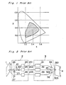
- the color recording by the use of ink jet printers with colored inks can give a reproductivity of tones falling within the hatched area in a CIE color standard chart (see Figure 1) and obtain a satisfactory reproduction of an image of natural color as far as the range of color reproductivity is concerned.
- the color reproduction is controlled in accordance with the subtractive mixing method by an ink jet printer in a color facsimile machine
- a simple linear masking method has failed to effect a satisfactory color correction, because numerous factors, such as the absorption characteristics of the three primary color pigments, the proportionality rule, the additivity rule, the printing characteristics of the recording paper and of the inks as well as other parameters are correlated with each other.
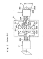
- separating means 2 such as three primary color separating optics, for separating the original color into three color components for each picture element of the original color image
- printing means 3 for recording the color components, namely a color ink jet printer 3 using inks with three different colors.
- the color separating means 2 includes a beam splitting system 28 comprising, for example, a filter or a dichroic mirror for separating a light beam reflected from an original color image 1 illuminated by a light source 27 into the three color components each having its own weight dependent upon a predetermined spectral characteristic; these obtained three color components are converted by respective logarithmic conversion amplifiers 24, 25 and 26 into three electrical signals 201, 202 and 203 which in combination correspond to the spectral distribution of the reflected light beam 11 and thereby of the original color image 1.
- a beam splitting system 28 comprising, for example, a filter or a dichroic mirror for separating a light beam reflected from an original color image 1 illuminated by a light source 27 into the three color components each having its own weight dependent upon a predetermined spectral characteristic; these obtained three color components are converted by respective logarithmic conversion amplifiers 24, 25 and 26 into three electrical signals 201, 202 and 203 which in combination correspond to the spectral distribution of the reflected light beam 11 and thereby of the original
- the printer 3 comprises, for example, three ink jet heads 34, 35 and 36 and their associated drive circuits 31, 32 and 33 to jet three color inks 301, 302 and 303 in respective amounts proportional to the electrical signals 201, 202 and 203 towards a recording medium 4 to form the duplicated color image, when the original color image 1 and the recorded medium 4 are moved in synchronism with each other.
- a color image duplicating device with the above structure cannot reproduce a practically utilizable color image of natural tone since the color reproductivity of the areas of mixed colors is insufficient due to the above described problems.
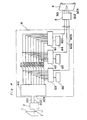
- Figure 3 shows another conventional color image duplicating device including in addition to the components shown in Figure 2 a so-called masking processing circuit 5 leading to an improvement over the device shown in Figure 2.
- the masking processing circuit 5 includes the weighting circuits 511,512,513, 521, 522, 523, 531, 532 and 533 for weighting the input signals 201, 202 and 203 as well as adders 51, 52 and 53 for performing an addition to give output signals 201, 202 and 203.
- Japanese laid-open Patent Publication No. 49-106714 discloses a color correction with non-linear characteristics. According to this publication, in order to obtain a desirable color print when color separated signals representative of red (R), green (G) and blue (B) are used as input signals, the corresponding amounts of cyan (C), magenta (M) and yellow (Y) inks are determined by selection from a table memory wherein C, M and Y signals representative of corrected colors corresponding to a combination of R, G and B have been stored. This method has some advantages since a relatively free color compensating curve can be introduced and the precision can be improved by the utilization of a digital engineering technology.
- a further masking process is known from DE-A-3 015 337 using either linear masking equations or the known square Clappers masking equation.
- the achieved color correction is not yet optimal.
- an ideal color reproduction characteristic can be obtained by the utilization of both arbitrary function forms and weighting coefficients.
- the matrix (aij) of coefficients can be calculated with no special means used, but by the use of the image duplicating device itself. More specifically, by utilizing the color separator of the color image duplicating device as a color measuring means and by applying a technique for measuring the characteristic of the color recorder, an optimum value can automatically be derived. Accordingly, by introducing the previously described algorithm for the calculation of the coefficients into the duplicating device itself, change of various conditions can be coped with.
- the coefficient in the case of an ink jet printer, can be optimized from time to time as desired relative to change in characteristic of the recording heads and/or change in type of the recording material such as inks and recording paper, thereby producing a high quality reproduced color image.
- the algorithm for the calculation of the coefficients can be realized by connecting a compact computer, for example, a microcomputer, with the calculator.
- the color image duplicating device may comprise means for simulating the non-linear characteristic with a polynominal expression wherein the color separated input signals are variables and for generating each term of the polynominal expression as a function, and means for giving a correction coefficient for each term as a parameter, so that a desirable corrected color output can easily be obtained at a high speed.
- a color image duplicating device for the purpose of the description of the present invention, the color separating and the recording will be described as using three colors as is the case with the previous description of the prior art duplicating devices.
- the output signals 201,202 and 203 received by a calculator 6 are converted by a function term generator 60 into a plurality of, for example, nine function groups 611, 612,...618 and 619 which are hereinafter referred to as f1, f2,...fj...f8 and f9.
- the linear adders 61, 62 and 63 are operable to produce the product and sum by the utilization of coefficients preset in the memories 64, 65 and 66 relative to nine inputs, respectively, and to generate outputs 601, 602 and 603, which are hereinafter referred to as y1, y2 and y3, respectively. Accordingly, assuming that the inputs 201, 202 and 203 are respectively expressed by x1, x2 and x3 and the contents of the coefficients of the memories 64, 65 and 66 are respectively expressed by alj, a2j and a3j wherein j represents 1, 2, 3...8 or 9, the following relationship can be obtained.
- the calculator 6 is separated from the duplicating device to eliminate the correction operation.
- Zk represents respective levels of drive signals supplied to the three input terminals in the case of the three color recorder now under discussion, k being expressed as follows: Affixes 1, 2 and 3 correspond to, for example, cyan, magenta and yellow colors of the recorder, respectively.
- Xk has three separated color components corresponding to Zk, the measured value of the k-th color sample being expressed as follows.
- the three separated color signals x1, x2 and x3 represent respective outputs representative of reflective indexes of the color separator, wherein 0 ⁇ x1, x2, x3 ⁇ 1. It is also to be noted that the last element 1 represents a component of the constant term.
- the multi-term equation has been described as a quadratic equation. However, it may be added with an equation of high degree to simulate a further complicated correction curve.
- a reciprocal term, a logarithmic term or an exponential function term may be employed other than that used to obtain a high degree of simulation depending on the purpose.
- the color image duplicating device is applicable in association with a device, such as a color facsimile machine or a color ink jet printer, for recording a color image having a half-tone onto a recording medium such as a paper, a cloth or other medium. Where it is applied in association with the ink jet recording device, it can result in a high fidelity color reproduction with no substantial difference in color between the original and the reproduced image.
Description
- The present invention relates to a color image duplicating device as acknowledged in the opening clause of claim 1 as well as to a method for calibrating such a device.
- Such a color image duplicating device can be used in a recording apparatus, such as a color facsimile machine and a color inkjet printer, of a type recording an image of natural color having a half-tone of color.
- A remarkable progress has recently been made in the field of image recording technology with ink jet printers which are increasingly used for recording color images. However, most of these techniques pertain to the reproduction of either a mere multi-color image or a pseudo-color image and do not consider the demand for devices capable of reproducing a color image with high fidelity.
- When color images are to be recorded by the use of an ink jet printer, the reproductivity of the color tends to be adversely affected by the following problems:
- (1) deviations from the proportionality rule of the single color density of the ink relative to the magnitude of the applied electrical signal, and
- (2) deviations from the additivity rule of the reproduced color density relative to the density of each color element during the recording in which inks of different colors are superimposed.
- On the other hand, according to recent developments, the color recording by the use of ink jet printers with colored inks can give a reproductivity of tones falling within the hatched area in a CIE color standard chart (see Figure 1) and obtain a satisfactory reproduction of an image of natural color as far as the range of color reproductivity is concerned.
- It is difficult, however, to produce an ink having optical characteristics free from the above problems (1) and (2), particularly the second above-mentioned problem (2), and at the sametime physical characteristics suitable for their use in an ink jet printer. Therefore attempts have been made to employ a linear or secondary functional masking method as used in printing processes; these masking methods, however, have not led to success.
- If, for example, the color reproduction is controlled in accordance with the subtractive mixing method by an ink jet printer in a color facsimile machine, a simple linear masking method has failed to effect a satisfactory color correction, because numerous factors, such as the absorption characteristics of the three primary color pigments, the proportionality rule, the additivity rule, the printing characteristics of the recording paper and of the inks as well as other parameters are correlated with each other.
- Hereinafter a conventional color image duplicating device will be described with particular reference to Figure 2 showing the fundamental arrangement of the components parts of such a color image duplicating device comprising separating
means 2, such as three primary color separating optics, for separating the original color into three color components for each picture element of the original color image, and printing means 3 for recording the color components, namely a colorink jet printer 3 using inks with three different colors. - The color separating means 2 includes a
beam splitting system 28 comprising, for example, a filter or a dichroic mirror for separating a light beam reflected from an original color image 1 illuminated by alight source 27 into the three color components each having its own weight dependent upon a predetermined spectral characteristic; these obtained three color components are converted by respectivelogarithmic conversion amplifiers electrical signals - The
printer 3 comprises, for example, threeink jet heads drive circuits color inks electrical signals recording medium 4 to form the duplicated color image, when the original color image 1 and the recordedmedium 4 are moved in synchronism with each other. - A color image duplicating device with the above structure cannot reproduce a practically utilizable color image of natural tone since the color reproductivity of the areas of mixed colors is insufficient due to the above described problems.
- Figure 3 shows another conventional color image duplicating device including in addition to the components shown in Figure 2 a so-called masking processing circuit 5 leading to an improvement over the device shown in Figure 2. The masking processing circuit 5 includes the weighting circuits 511,512,513, 521, 522, 523, 531, 532 and 533 for weighting the
input signals adders output signals input signals output signals 
- If the values for bij are carefully selected, a duplicated color image with improved color reproductivity can be obtained.
- However, this linear masking processing as a rule cannot eliminate any possible faults in color reproductivity resulting from the non-linear characteristics in the above problems (1) and (2).
- Japanese laid-open Patent Publication No. 49-106714 discloses a color correction with non-linear characteristics. According to this publication, in order to obtain a desirable color print when color separated signals representative of red (R), green (G) and blue (B) are used as input signals, the corresponding amounts of cyan (C), magenta (M) and yellow (Y) inks are determined by selection from a table memory wherein C, M and Y signals representative of corrected colors corresponding to a combination of R, G and B have been stored. This method has some advantages since a relatively free color compensating curve can be introduced and the precision can be improved by the utilization of a digital engineering technology.
- However, even this method has the following disadvantage: Since all possible combinations of the values for C, M and Y must be stored relative to all possible combinations of the values for R, G and B, the device itself tends to be complicated in structure and expensive as is evident from the fact that the Japanese laid-open Publication No. 49-106714 and its related Japanese laid-open Patent Publication DE-A-2 632 003, DE-A-2 637 055 and DE-A-2 640 833 disclose improvements for saving storing space and for efficiently performing the calculation with the correction amount divided into variable and fixed elements. However, even when these improvements are to be utilized, a practical circuit arrangement can hardly be realized and, if possible, will become expensive.
- A further masking process is known from DE-A-3 015 337 using either linear masking equations or the known square Clappers masking equation. The achieved color correction, however, is not yet optimal.
- In accordance with one aspect it is therefore the object of the invention to provide a color image duplicating device of the above explained type wherein the relationship between the input level at each of the input terminals and the density of the output color image corresponding thereto can be approximated to each other with a masking equation of low degree to ensure an effective correction of the color reproduction so that a high quality color image having a minimized color difference between the original color image and the reproduced color image is obtained.
- This object is achieved by the features of the characterizing part of claim 1. Suitable embodiments are defined by the features of the
sub-claims 2 to 6. - In accordance with another aspect it is the object of the invention to provide a method for calibrating such a color image duplicating device.
- This object is achieved by the features of the characterizing part of claim 7. A suitable embodiment is defined by the feature of claim 8.
- According to the present invention, even for a color printing means which exhibits a complicated irregularity which cannot be simulated by the conventional masking equation, an ideal color reproduction characteristic can be obtained by the utilization of both arbitrary function forms and weighting coefficients.
- Moreover, the matrix (aij) of coefficients can be calculated with no special means used, but by the use of the image duplicating device itself. More specifically, by utilizing the color separator of the color image duplicating device as a color measuring means and by applying a technique for measuring the characteristic of the color recorder, an optimum value can automatically be derived. Accordingly, by introducing the previously described algorithm for the calculation of the coefficients into the duplicating device itself, change of various conditions can be coped with.
- By way of example, in the case of an ink jet printer, the coefficient can be optimized from time to time as desired relative to change in characteristic of the recording heads and/or change in type of the recording material such as inks and recording paper, thereby producing a high quality reproduced color image. The algorithm for the calculation of the coefficients can be realized by connecting a compact computer, for example, a microcomputer, with the calculator.
- Furthermore, according to the present invention, the color image duplicating device may comprise means for simulating the non-linear characteristic with a polynominal expression wherein the color separated input signals are variables and for generating each term of the polynominal expression as a function, and means for giving a correction coefficient for each term as a parameter, so that a desirable corrected color output can easily be obtained at a high speed.
- These and other objects and features of the present invention will become clear from the subsequent description in connection with a preferred embodiment thereof with reference to the accompanying drawings, in which,
- Fig. 1 is a chart showing a preferred range of color reproduction achieved by the ink jet recording device;
- Fig. 2 is a circuit block diagram showing the fundamental structure of a conventional color image duplicating device,
- Fig. 3 is a circuit block diagram showing the structure of a conventional color image duplicating device using primary masking, and
- Fig. 4 is a circuit block diagram showing a color image duplicating device according to a preferred embodiment of the present invention.
- Referring to Fig. 4, there is shown a preferred embodiment of a color image duplicating device according to the present invention. For the purpose of the description of the present invention, the color separating and the recording will be described as using three colors as is the case with the previous description of the prior art duplicating devices. The output signals 201,202 and 203 received by a calculator 6 are converted by a
function term generator 60 into a plurality of, for example, ninefunction groups function term generator 60 is operable to generate row vectors F(X) of new n degree having as their elements n (in this case, n=9) functions f1, f2,...fj...f8 and f9 wherein elements of X are variables relative to the color separated vector data X which is outputs from the color separating means 2. More specifically, so that the color separated vector data X supplied can be utilized as address data to derive the value of the function F(X) readily, it may be constructed in the form of a table memory wherein the output F relative to X is stored in the form of a table. - The
linear adders memories outputs inputs memories 
- These y1, y2 and y3 drive the
color printer 3 to effect the reproduction of a duplicated color image on therecording medium 4. If one desires to obtain a complete and faithful reproduction of the color image, the form of the function fi and the value of the coefficient aij must be determined. However, since it is generally difficult to completely express the value of the spectral density of each ink on therecording medium 4 relative to the original color system in the form of a function wherein the input level is a variable in a masking equation, the equation (2) above cannot readily be determined. - However, in practice, in the case of the color recorder wherein an ink jet recording head of an on-demand type is utilized, a series of experiments conducted have shown that, if x1, x2, x3, x12, x22, x33, x1 - x2, x2 - x3, or x3 - x1 is used for fj when the input xi represents the density relative to the three colors of red, green and blue, a satisfactory correction result can be obtained.
- Hereinafter, a method for the determination of an optimum value for the coefficient aij in the present invention when the function fj has been determined will be described. In the first place, the calculator 6 is separated from the duplicating device to eliminate the correction operation. In this condition, a combination Zk (k=1, 2,...N) of inputs falling within the range of the
input vectors printer 3 is prepared at random or as a combination of suitable values, and is successively applied to input terminals of theprinter 3 to give a color sample of N colors. N should be a value sufficiently larger than the number of the coefficients aij (in this case, 27 because i=1 to 3 and j=1 to 9). Zk represents respective levels of drive signals supplied to the three input terminals in the case of the three color recorder now under discussion, k being expressed as follows:
Affixes - In the next place, the color sample of the N colors is supplied to the color separating means 2 to effect a color separation and, then, N combinations of electrical signals Xk (k=1, 2,...N) appearing at the
output terminals 
- If at this time (aij) is so determined as to establish the following relationship;


- More specifically, it is satisfactory to solve simultaneous equations (in this case, three sets of nine simultaneous equations) obtained by differentiating the equation (5) above with each aij.
- That is, since the following relationship can be established relative to each element aln in the matrix (aij);


- For the purpose of simplification, if:


- From the foregoing, the conditions for the minimized error with respect to all n and j can be obtained as a solution to the following matrix equation:

- The functions fj(x1, x2, x3) in the equation (2) above are, so far as the above example is concerned, in the form of a quadratic equation. However, by increasing the degree, for example, by adding higher degree terms such as x1 3, x2 3, x33, x12. x2, x22. x3, x32. x1, x1 x2 - x3, and so on, the preciseness of the color reproduction can further be improved. Moreover, even if the same terms are employed, it is possible to obtain the correction effect suited for the non-linearity of the recorder and the recording material by suitably selecting the form of the functions. Table 1 illustrate the forms of six functions different from the above quadratic equations. However, in Table 1, the three separated color signals x1, x2 and x3 represent respective outputs representative of reflective indexes of the color separator, wherein 0<x1, x2, x3<1. It is also to be noted that the last element 1 represents a component of the constant term.
- Results of comparison experiments wherein 512 color samples were actually prepared by the use of the color ink jet recorder with respect to these six function groups, optimum coefficients were then calculated and the magnitudes of reproduction errors were converted into level values of the three color (cyan, magenta and yellow) signals applied to the recorder, are tabulated in Table 2, from which is is clear that the function group 1 brought about the best result.


- As hereinbefore described, it is also possible to set the group of the functions and the coefficient, to make all of the function generating means, the memory and the calculating means in the form of a digital memory device and to make the output Y corresponding to X memorized in the form of a table so that the result Y can readily be derived with the input X used as an address data.
- It is to be noted that the multi-term equation has been described as a quadratic equation. However, it may be added with an equation of high degree to simulate a further complicated correction curve. In addition, for each function term, a reciprocal term, a logarithmic term or an exponential function term may be employed other than that used to obtain a high degree of simulation depending on the purpose.
- The foregoing arrangement can readily and economically be realized by the use of a recently developed digital integrated circuit component and, therefore, a relatively high preciseness can be warranted as compared with the conventional analog system. Especially in the present invention, it is possible to easily change the contents of each correction function term and the correction coefficient according to optimum conditions required to be attained and also to intensively modify various non-linear deviations contained in the process from the color separation input system to the color recording device, thereby achieving a real time processing and a versatility.
- The color image duplicating device according to the present invention is applicable in association with a device, such as a color facsimile machine or a color ink jet printer, for recording a color image having a half-tone onto a recording medium such as a paper, a cloth or other medium. Where it is applied in association with the ink jet recording device, it can result in a high fidelity color reproduction with no substantial difference in color between the original and the reproduced image.
Claims (8)
characterized by the following features:

Applications Claiming Priority (4)
| Application Number | Priority Date | Filing Date | Title |
|---|---|---|---|
| JP55179424A JPS57101840A (en) | 1980-12-17 | 1980-12-17 | Color image duplicator |
| JP179424/80 | 1980-12-17 | ||
| JP179423/80 | 1980-12-17 | ||
| JP55179423A JPS57131172A (en) | 1980-12-17 | 1980-12-17 | Color compensating and operating device |
Publications (3)
| Publication Number | Publication Date |
|---|---|
| EP0054313A2 EP0054313A2 (en) | 1982-06-23 |
| EP0054313A3 EP0054313A3 (en) | 1985-11-06 |
| EP0054313B1 true EP0054313B1 (en) | 1989-11-15 |
Family
ID=26499278
Family Applications (1)
| Application Number | Title | Priority Date | Filing Date |
|---|---|---|---|
| EP81110552A Expired EP0054313B1 (en) | 1980-12-17 | 1981-12-17 | Colour image duplicating device and method |
Country Status (3)
| Country | Link |
|---|---|
| US (1) | US4458265A (en) |
| EP (1) | EP0054313B1 (en) |
| DE (1) | DE3177123D1 (en) |
Cited By (1)
| Publication number | Priority date | Publication date | Assignee | Title |
|---|---|---|---|---|
| DE4334712A1 (en) * | 1993-10-12 | 1995-04-13 | Heidelberger Druckmasch Ag | Reproduction system |
Families Citing this family (20)
| Publication number | Priority date | Publication date | Assignee | Title |
|---|---|---|---|---|
| JPS5971865A (en) * | 1982-10-19 | 1984-04-23 | Nec Corp | Color ink jet printer |
| US4544945A (en) * | 1983-06-07 | 1985-10-01 | Rca Corporation | Logarithmic color matrix for a digital television receiver |
| US4665435A (en) * | 1983-06-16 | 1987-05-12 | Matsushita Electric Industrial Co., Ltd. | Method and circuit arrangement for producing color picture signals for color reproduction |
| US4680625A (en) * | 1984-07-18 | 1987-07-14 | Konishiroku Photo Industry Co., Ltd. | Method and apparatus for multicolor image forming |
| US4970584A (en) * | 1985-05-15 | 1990-11-13 | Ricoh Company, Ltd. | Method and apparatus for the compensation of color detection |
| US4670780A (en) * | 1985-05-28 | 1987-06-02 | Tektronix, Inc. | Method of matching hardcopy colors to video display colors in which unreachable video display colors are converted into reachable hardcopy colors in a mixture-single-white (MSW) color space |
| US4758885A (en) * | 1985-06-17 | 1988-07-19 | Canon Kabushiki Kaisha | Method of processing color image |
| JP2538555B2 (en) * | 1985-07-16 | 1996-09-25 | 富士写真フイルム株式会社 | Image hard copy making device |
| US4864391A (en) * | 1986-05-09 | 1989-09-05 | Canon Kabushiki Kaisha | Image processing apparatus for color correcting an image which can monitor the result of the color correction |
| JPS63278470A (en) * | 1987-05-09 | 1988-11-16 | Sharp Corp | Color conversion method |
| US4992863A (en) * | 1987-12-22 | 1991-02-12 | Minolta Camera Kabushiki Kaisha | Colored image reading apparatus |
| US5239370A (en) * | 1990-04-24 | 1993-08-24 | Brother Kogyo Kabushiki Kaisha | Color image forming apparatus having color-correcting unit operating in accordance with a gamut of an image input medium |
| US5282046A (en) * | 1990-07-25 | 1994-01-25 | Brother Kogyo Kabushiki Kaisha | Color image forming apparatus having a color-correcting unit |
| JP3049745B2 (en) * | 1990-08-20 | 2000-06-05 | ブラザー工業株式会社 | Color image recording device |
| JP3052352B2 (en) * | 1990-08-20 | 2000-06-12 | ブラザー工業株式会社 | Color correction processing device |
| US5237409A (en) * | 1990-09-10 | 1993-08-17 | Brother Kogyo Kabushiki Kaisha | Color image forming apparatus using color compressed color data |
| JPH04241368A (en) * | 1991-01-16 | 1992-08-28 | Brother Ind Ltd | Color image recorder |
| US5657137A (en) * | 1992-05-04 | 1997-08-12 | Hewlett-Packard Company | Color digital halftoning using black and secondary color replacement |
| US5677967A (en) * | 1993-03-10 | 1997-10-14 | R. R. Donnelley & Sons Company | Method of and apparatus for converting between a color appearance space and a colorant space |
| IL115026A (en) * | 1995-08-21 | 2001-03-19 | Scitex Corp Ltd | Method for matching colors of an object to printing colors |
Family Cites Families (9)
| Publication number | Priority date | Publication date | Assignee | Title |
|---|---|---|---|---|
| JPS5224701A (en) * | 1975-08-20 | 1977-02-24 | Dainippon Screen Mfg | Method of correcting color of image signal |
| US4275413A (en) * | 1978-03-30 | 1981-06-23 | Takashi Sakamoto | Linear interpolator for color correction |
| US4305093A (en) * | 1978-06-22 | 1981-12-08 | International Electronic Photo Process Laboratory Co., Ltd. | Method of producing multiple images in a scanning apparatus |
| DE2848376C2 (en) * | 1978-11-08 | 1983-12-15 | Dr.-Ing. Rudolf Hell Gmbh, 2300 Kiel | Device for post-correction of standard color corrections in color image recording |
| JPS5579448A (en) * | 1978-12-11 | 1980-06-14 | Dainippon Screen Mfg Co Ltd | Color separation simulation system |
| IL59886A (en) * | 1979-04-23 | 1983-06-15 | Dainippon Screen Mfg | Digital color control method and machine |
| JPS55142345A (en) * | 1979-04-23 | 1980-11-06 | Dainippon Screen Mfg Co Ltd | Masking operation method in digital color tone control |
| US4344086A (en) * | 1979-11-20 | 1982-08-10 | Nippon Electric Co., Ltd. | Encoder for encoding a multilevel pel signal sequence with probability representative mode codes allotted to prediction error codes for each pel signal and a decoder therefor |
| US4307415A (en) * | 1980-04-30 | 1981-12-22 | United Technologies Corporation | Color indentification circuit |
-
1981
- 1981-12-17 US US06/332,098 patent/US4458265A/en not_active Expired - Lifetime
- 1981-12-17 EP EP81110552A patent/EP0054313B1/en not_active Expired
- 1981-12-17 DE DE8181110552T patent/DE3177123D1/en not_active Expired
Cited By (1)
| Publication number | Priority date | Publication date | Assignee | Title |
|---|---|---|---|---|
| DE4334712A1 (en) * | 1993-10-12 | 1995-04-13 | Heidelberger Druckmasch Ag | Reproduction system |
Also Published As
| Publication number | Publication date |
|---|---|
| DE3177123D1 (en) | 1989-12-21 |
| US4458265A (en) | 1984-07-03 |
| EP0054313A2 (en) | 1982-06-23 |
| EP0054313A3 (en) | 1985-11-06 |
Similar Documents
| Publication | Publication Date | Title |
|---|---|---|
| EP0054313B1 (en) | Colour image duplicating device and method | |
| US4926254A (en) | Method of correcting color image data for obtaining proof image | |
| US5528377A (en) | Extended density color printing | |
| US5162899A (en) | Color data correction apparatus ultilizing neural network | |
| EP0475554B1 (en) | Apparatus and method for colour calibration | |
| EP0483132B1 (en) | Apparatus and method for producing color corrected reproduction of coloured original images | |
| US5305119A (en) | Color printer calibration architecture | |
| US5448379A (en) | Method and apparatus for forming color images by converting a color signal to a further color density signal | |
| JPH0522227B2 (en) | ||
| US5857063A (en) | Multicolorant process control | |
| US5463471A (en) | Method and system of color halftone reproduction | |
| JPS6338155B2 (en) | ||
| JPH0151828B2 (en) | ||
| US5422738A (en) | Color image forming method and an apparatus employed therefor, and a correction factor determining method | |
| GB2191905A (en) | A method for color correction | |
| JPH0572577B2 (en) | ||
| US5008742A (en) | Dot signal conversion method | |
| US4349835A (en) | Color printing process simulator | |
| US4774567A (en) | Reproduction of colored images including overprinting for reproduction of bright colors | |
| US4959712A (en) | Method and apparatus for color adjustment | |
| EP0505984B1 (en) | Color video still image processing system | |
| EP0426113A2 (en) | Method of and apparatus for recording colour image | |
| US5196927A (en) | Method for electronic color processing | |
| GB2240897A (en) | Color correction and printing system for reproduction of computer-generated images | |
| JPH0767130B2 (en) | Halftone dot area ratio determination device |
Legal Events
| Date | Code | Title | Description |
|---|---|---|---|
| PUAI | Public reference made under article 153(3) epc to a published international application that has entered the european phase |
Free format text: ORIGINAL CODE: 0009012 |
|
| AK | Designated contracting states |
Designated state(s): DE FR GB |
|
| PUAL | Search report despatched |
Free format text: ORIGINAL CODE: 0009013 |
|
| AK | Designated contracting states |
Designated state(s): DE FR GB |
|
| 17P | Request for examination filed |
Effective date: 19860410 |
|
| 17Q | First examination report despatched |
Effective date: 19870908 |
|
| GRAA | (expected) grant |
Free format text: ORIGINAL CODE: 0009210 |
|
| AK | Designated contracting states |
Kind code of ref document: B1 Designated state(s): DE FR GB |
|
| REF | Corresponds to: |
Ref document number: 3177123 Country of ref document: DE Date of ref document: 19891221 |
|
| ET | Fr: translation filed | ||
| PLBE | No opposition filed within time limit |
Free format text: ORIGINAL CODE: 0009261 |
|
| STAA | Information on the status of an ep patent application or granted ep patent |
Free format text: STATUS: NO OPPOSITION FILED WITHIN TIME LIMIT |
|
| 26N | No opposition filed | ||
| PGFP | Annual fee paid to national office [announced via postgrant information from national office to epo] |
Ref country code: GB Payment date: 19931207 Year of fee payment: 13 |
|
| PGFP | Annual fee paid to national office [announced via postgrant information from national office to epo] |
Ref country code: DE Payment date: 19931208 Year of fee payment: 13 |
|
| PGFP | Annual fee paid to national office [announced via postgrant information from national office to epo] |
Ref country code: FR Payment date: 19931209 Year of fee payment: 13 |
|
| PG25 | Lapsed in a contracting state [announced via postgrant information from national office to epo] |
Ref country code: GB Effective date: 19941217 |
|
| GBPC | Gb: european patent ceased through non-payment of renewal fee |
Effective date: 19941217 |
|
| PG25 | Lapsed in a contracting state [announced via postgrant information from national office to epo] |
Ref country code: FR Effective date: 19950831 |
|
| PG25 | Lapsed in a contracting state [announced via postgrant information from national office to epo] |
Ref country code: DE Effective date: 19950901 |
|
| REG | Reference to a national code |
Ref country code: FR Ref legal event code: ST |