EP0203207A1 - System for testing magnetic head/disk interfaces - Google Patents
System for testing magnetic head/disk interfaces Download PDFInfo
- Publication number
- EP0203207A1 EP0203207A1 EP85105722A EP85105722A EP0203207A1 EP 0203207 A1 EP0203207 A1 EP 0203207A1 EP 85105722 A EP85105722 A EP 85105722A EP 85105722 A EP85105722 A EP 85105722A EP 0203207 A1 EP0203207 A1 EP 0203207A1
- Authority
- EP
- European Patent Office
- Prior art keywords
- disk
- slider
- measuring
- tribo
- current
- Prior art date
- Legal status (The legal status is an assumption and is not a legal conclusion. Google has not performed a legal analysis and makes no representation as to the accuracy of the status listed.)
- Ceased
Links
Images
Classifications
-
- G—PHYSICS
- G11—INFORMATION STORAGE
- G11B—INFORMATION STORAGE BASED ON RELATIVE MOVEMENT BETWEEN RECORD CARRIER AND TRANSDUCER
- G11B33/00—Constructional parts, details or accessories not provided for in the other groups of this subclass
- G11B33/10—Indicating arrangements; Warning arrangements
-
- G—PHYSICS
- G11—INFORMATION STORAGE
- G11B—INFORMATION STORAGE BASED ON RELATIVE MOVEMENT BETWEEN RECORD CARRIER AND TRANSDUCER
- G11B17/00—Guiding record carriers not specifically of filamentary or web form, or of supports therefor
- G11B17/32—Maintaining desired spacing between record carrier and head, e.g. by fluid-dynamic spacing
-
- G—PHYSICS
- G11—INFORMATION STORAGE
- G11B—INFORMATION STORAGE BASED ON RELATIVE MOVEMENT BETWEEN RECORD CARRIER AND TRANSDUCER
- G11B5/00—Recording by magnetisation or demagnetisation of a record carrier; Reproducing by magnetic means; Record carriers therefor
- G11B5/012—Recording on, or reproducing or erasing from, magnetic disks
-
- G—PHYSICS
- G11—INFORMATION STORAGE
- G11B—INFORMATION STORAGE BASED ON RELATIVE MOVEMENT BETWEEN RECORD CARRIER AND TRANSDUCER
- G11B5/00—Recording by magnetisation or demagnetisation of a record carrier; Reproducing by magnetic means; Record carriers therefor
- G11B5/48—Disposition or mounting of heads or head supports relative to record carriers ; arrangements of heads, e.g. for scanning the record carrier to increase the relative speed
- G11B5/58—Disposition or mounting of heads or head supports relative to record carriers ; arrangements of heads, e.g. for scanning the record carrier to increase the relative speed with provision for moving the head for the purpose of maintaining alignment of the head relative to the record carrier during transducing operation, e.g. to compensate for surface irregularities of the latter or for track following
Definitions
- the present invention generally relates to magnetic disk storage technology and, more particularly, to the evaluation, measuring and testing of the properties of head/disk interfaces.
- this method allows a good characterization of the interaction between slider and disk surfaces.
- the invention measures and analyzes the friction induced triboelectric current flowing between disk and slider when they are in rubbing contact.
- the invention basically endeavours to measure a triboelectric current flowing between disk and slider, and to analyze this triboelectric current with respect to its amplitude and time dependence.
- Fig. 1 shows a set-up for measuring the triboelectric current (hereafter shortly called tribo current).
- a magnetic disk 1 with two coated sides A and B is mounted on a spindle 2, driven by a motor 3.
- a spindle bearing 4 is contained in a housing 5.
- a slider 6 mounted on a suspension 7 flies on the disk.
- Suspension 7 is mounted on an arm 8 which is fixed electrically isolated to a carriage 10 movable on housing 5.
- An electrical connection 12 feeds the measured tribo current from arm 8 into an operational amplifier 14.
- a similar equipment is provided for side B of disk 1.
- a plotter and analyzer apparatus 16 allows to plot and analyze tribo current curves.
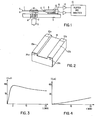
- Fig. 2 shows details of a slider construction in accordance with the booklet cited above, p. 13, and U.S. Patent 4,218,715.
- the slider 18 has two rails 20a and 20b sliding by means of an air bearing over the disk surface, at an operational speed of appr. 3600 rpm. As is customary, the rails each start, at their leading portion with respect to a moving track of the disk, with a tapered section 22a and 22b, respectively.
- Two thin film transducer heads 24a and 24b are mounted on the trailing edge of the slider.
- slider 6 is made of a ceramic mixture comprising aluminum oxide (AI203) and titan carbide (TiC).
- AI203 aluminum oxide
- TiC titan carbide
- a magnetic disk which is particularly well suited for the purpose of the present invention consists of an aluminum magnesium alloy substrate coated with iron oxide (Fe 2 0 3 ) and aluminum oxide (A1 2 0 3 ) particles dispersed in an epoxy resin.
- slider 6 is first run-in (conditioned) on a first track and then positioned on another track.
- the tribo current I measured during the testing time interval is as shown in Fig. 3.
- An early maximum is obtained normally within the first 15 minutes after the start of the test and then the amplitude of the tribo current decreases slowly.
- the estimated lifetime can be defined, for instance, by the time when the tribo current has decayed to 10 % of its maximum. A measuring time period of 8 hours may become necessary which is, however, much shorter than the 200 hours necessary for the tests made up till now.
- the height of the maximum of the tribo current depends on the rotational speed and on the quantity and quality of the lube distributed over the disk. To obtain a tribo current, there must be a frictional, i.e. rubbing contact between disk and slider. For this purpose a rotational speed of 100-500 rpm is chosen which results in a flying height of 0-100 nanometers.
- a lube which contains fluor yielding good tribo current amplitudes.
- measuring the tribo current allows to obtain an indication on the quality of the surfaces of the disk and the slider rails. It has already been stated that the curve shown in Fig. 3 is obtained for a good slider which may be called "superslider". The tribo current is very much dependent on changes in the disk/slider interface, on the disk surface, on the slider surface and on the lube quantity, quality and distribution. Therefore it has become possible to detect a superslider structure by the shape of the tribo current curve shown in Fig. 3, which essentially shows an early maximum and a subsequent slow decay.
- the tribo current measuring method serves to detect unsymmetries between both sides of a disk. Measurings have shown that A/B side asymmetries of disks have a pronounced influence on the tribo current: for disks whose A sides have been tested in buff direction the tribo current signal was approximately twice as high as in the test of the B sides going against buff direction. Furthermore, the time curve of the tribo current was different in both cases.
- the tribo current is very sensitive to changes of the present operating conditions. This applies also to very small deflections of the slider with respect to the magnetic track. These deflections can be caused e.g. by slackness of the spindle bearing 4 in housing 5. The method as disclosed by the invention therefore also permits the detection of such insufficiencies in the spindle bearing.
Abstract
Description
- The present invention generally relates to magnetic disk storage technology and, more particularly, to the evaluation, measuring and testing of the properties of head/disk interfaces.
- The characteristics of the head/disk interface play an important part for the lifetime of the storage system. Until now, forecasts on the lifetime of the system had been possible only on the basis of lengthy tests which regularly ended in the destruction of the parts tested. To give an example: start/stop tests have been repeatedly carried out until the breakdown of the system, which on an average took 200 hours.
- Of considerable importance is the nature and quality of the surfaces which slide on each other, i.e. of the disk on the one hand and the rail of the slider carrying the head on the other. Up to now there did not exist any measuring methods for the substantially precise and useful determination of the quality of these surfaces. The quality of the interface has been proved to be determined by the quantity and quality of a lube used. However, until now the connections between slider flight characteristics and lube could not be measured adequately.
- For a general introduction to disk storage technology reference may be had to the booklet "Disk Storage Technology" of International Business Machines, 1980. In this booklet, two-rail sliders are described, for instance, on pp. 8 and 13. Such sliders with thin film heads are also described in U.S. Patent 4,218,715 and in IBM TDB, December 19.83, pp. 3364 and 3365.
- Further, a magnetic head suspension mount apparatus is described in U.S. Patent 4,167,765.
- It is therefore an object of the invention to provide a method of measuring and testing the interface between slider and disk in a magnetic disk storage apparatus, which is precise and normally non-destructive.
- According to a further object of the invention this method allows a good characterization of the interaction between slider and disk surfaces.
- It is another object of the invention to provide a method allowing a generally non-destructive prediction of the head/disk assembly lifetime.
- To achieve the above described objects the invention measures and analyzes the friction induced triboelectric current flowing between disk and slider when they are in rubbing contact.
-
- Fig. 1 shows a magnetic disk storage testing and measuring set-up,
- Fig. 2 shows a slider,
- Fig. 3 shows the amplitude of the measured triboelectric current over the measuring time interval, for a very good slider, and
- Fig. 4 shows the amplitude of the measured triboelectric current during the measuring time period, for a normal slider.
- As already stated, the invention basically endeavours to measure a triboelectric current flowing between disk and slider, and to analyze this triboelectric current with respect to its amplitude and time dependence.
- Only very little is known about the use of triboelectric currents for measuring and testing purposes. One example has been described in British Patent 1,430,390, which relates to the production of electric cables, and their inspection as to breaks. The subsequently described method, however, is nowhere explained or suggested in the prior art.
- Fig. 1 shows a set-up for measuring the triboelectric current (hereafter shortly called tribo current). A magnetic disk 1 with two coated sides A and B is mounted on a
spindle 2, driven by amotor 3. A spindle bearing 4 is contained in ahousing 5. With respect to side A, aslider 6 mounted on asuspension 7 flies on the disk.Suspension 7 is mounted on anarm 8 which is fixed electrically isolated to acarriage 10 movable onhousing 5. Anelectrical connection 12 feeds the measured tribo current fromarm 8 into anoperational amplifier 14. A similar equipment is provided for side B of disk 1. A plotter andanalyzer apparatus 16 allows to plot and analyze tribo current curves. - Fig. 2 shows details of a slider construction in accordance with the booklet cited above, p. 13, and U.S. Patent 4,218,715. The
slider 18 has tworails tapered section 22a and 22b, respectively. Two thinfilm transducer heads -
Slider 6 in Fig. 1 withsuspension 7 mounted onarm 8 is moved together withcarriage 10 to position the slider over the desired disk track. - In accordance with a preferred embodiment of the
present invention slider 6 is made of a ceramic mixture comprising aluminum oxide (AI203) and titan carbide (TiC). The inclusion of titancarbide renders slider 6 sufficiently conductive to allow conduction of the tribo current. - A magnetic disk which is particularly well suited for the purpose of the present invention consists of an aluminum magnesium alloy substrate coated with iron oxide (Fe203) and aluminum oxide (A1203) particles dispersed in an epoxy resin.
- To obtain an indication of the lifetime of the disk/ slider assembly to be expected,
slider 6 is first run-in (conditioned) on a first track and then positioned on another track. In the presence of good sliding properties the tribo current I measured during the testing time interval is as shown in Fig. 3. An early maximum is obtained normally within the first 15 minutes after the start of the test and then the amplitude of the tribo current decreases slowly. The estimated lifetime can be defined, for instance, by the time when the tribo current has decayed to 10 % of its maximum. A measuring time period of 8 hours may become necessary which is, however, much shorter than the 200 hours necessary for the tests made up till now. - The height of the maximum of the tribo current depends on the rotational speed and on the quantity and quality of the lube distributed over the disk. To obtain a tribo current, there must be a frictional, i.e. rubbing contact between disk and slider. For this purpose a rotational speed of 100-500 rpm is chosen which results in a flying height of 0-100 nanometers.
- According to the invention a lube is used which contains fluor yielding good tribo current amplitudes.
- As the described method for measuring the lifetime is not based on the destruction of the assembly it is not necessary to wait for this destruction. Also, it has by this method become economically possible to test all interfaces and not only selected (mostly baqJ ones.
- In another mode of operation measuring the tribo current allows to obtain an indication on the quality of the surfaces of the disk and the slider rails. It has already been stated that the curve shown in Fig. 3 is obtained for a good slider which may be called "superslider". The tribo current is very much dependent on changes in the disk/slider interface, on the disk surface, on the slider surface and on the lube quantity, quality and distribution. Therefore it has become possible to detect a superslider structure by the shape of the tribo current curve shown in Fig. 3, which essentially shows an early maximum and a subsequent slow decay.
- In contrast thereto, for a normal slider a curve as shown in Fig. 4 is obtained which shows a continuous increase of the tribo current. This increase is due to increased friction which, of course, can lead to a destruction of the assembly. It has been found, that a superslider structure can be obtained by the above described conditioning of the slider on a special track or by mechanical or chemical treatment of the slider rails as e.g. described in European Patent Application EP-A-90055. It is evident, that the measuring and testing method of the present invention permits to obtain significant advantages in the production of magnetic head sliders.
- In a still different mode of operation the tribo current measuring method according to the invention serves to detect unsymmetries between both sides of a disk. Measurings have shown that A/B side asymmetries of disks have a pronounced influence on the tribo current: for disks whose A sides have been tested in buff direction the tribo current signal was approximately twice as high as in the test of the B sides going against buff direction. Furthermore, the time curve of the tribo current was different in both cases.
- However, if both disk sides were tested in their processing direction there was no such asymmetry. With the method as disclosed by the invention it is therefore possible to detect steps during the manufacturing process of the magnetic disks which cause the so-called asymmetries, and to convert these steps from going against buff direction to going in buff direction. It should be taken into consideration that during the conventional operation of the magnetic disk storage the magnetic head on the A side of the disk sees a disk surface rotating to the left, but on the B side of the disk a disk surface rotating to the right.
- It has already been indicated that the tribo current is very sensitive to changes of the present operating conditions. This applies also to very small deflections of the slider with respect to the magnetic track. These deflections can be caused e.g. by slackness of the spindle bearing 4 in
housing 5. The method as disclosed by the invention therefore also permits the detection of such insufficiencies in the spindle bearing.
Claims (10)
characterized by the following steps:
Priority Applications (4)
| Application Number | Priority Date | Filing Date | Title |
|---|---|---|---|
| EP85105722A EP0203207A1 (en) | 1985-05-10 | 1985-05-10 | System for testing magnetic head/disk interfaces |
| CA000503284A CA1242272A (en) | 1985-05-10 | 1986-03-04 | System for testing magnetic head/disk interfaces |
| JP61076852A JPS62161040A (en) | 1985-05-10 | 1986-04-04 | Method of measuring interface characteristic |
| US06/856,306 US4724392A (en) | 1985-05-10 | 1986-04-28 | System for testing magnetic head/disk interfaces |
Applications Claiming Priority (1)
| Application Number | Priority Date | Filing Date | Title |
|---|---|---|---|
| EP85105722A EP0203207A1 (en) | 1985-05-10 | 1985-05-10 | System for testing magnetic head/disk interfaces |
Publications (1)
| Publication Number | Publication Date |
|---|---|
| EP0203207A1 true EP0203207A1 (en) | 1986-12-03 |
Family
ID=8193493
Family Applications (1)
| Application Number | Title | Priority Date | Filing Date |
|---|---|---|---|
| EP85105722A Ceased EP0203207A1 (en) | 1985-05-10 | 1985-05-10 | System for testing magnetic head/disk interfaces |
Country Status (4)
| Country | Link |
|---|---|
| US (1) | US4724392A (en) |
| EP (1) | EP0203207A1 (en) |
| JP (1) | JPS62161040A (en) |
| CA (1) | CA1242272A (en) |
Cited By (3)
| Publication number | Priority date | Publication date | Assignee | Title |
|---|---|---|---|---|
| WO1996019802A1 (en) * | 1994-12-19 | 1996-06-27 | Seagate Technology, Inc. | A method for determining an outer diameter rolloff in a process for making magnetic disks |
| WO1996022596A2 (en) * | 1995-01-19 | 1996-07-25 | Seagate Technology, Inc. | Non-destructive in-situ landing velocity determination of magnetic rigid disk drives |
| CN110006818A (en) * | 2019-02-20 | 2019-07-12 | 常州大学 | A kind of pin-disc type corrosive wear experimental rig |
Families Citing this family (8)
| Publication number | Priority date | Publication date | Assignee | Title |
|---|---|---|---|---|
| JPH0697224B2 (en) * | 1988-07-13 | 1994-11-30 | 鐘紡株式会社 | Friction electrification voltage measuring device |
| US5038625A (en) * | 1989-01-31 | 1991-08-13 | Seagate Technology, Inc. | Tribological head-disk interface testing system |
| US5305165A (en) * | 1991-12-24 | 1994-04-19 | International Business Machines Corporation | Tribo-attractive contact data storage system |
| US6032262A (en) * | 1995-04-18 | 2000-02-29 | Emc Corporation | Disk drive reliability determination system and method |
| US6483657B1 (en) | 1998-09-14 | 2002-11-19 | Seagate Technology Llc | Head flight characterization using thermal asperity detection |
| US6466392B1 (en) | 1998-09-14 | 2002-10-15 | Seagate Technology Llc | Head flight characterization using a non-contact voltmeter |
| US7580759B2 (en) * | 2007-09-05 | 2009-08-25 | Hitachi Global Storage Technologies Netherlands B.V. | Systems and methods for in-situ recording head burnishing |
| US7952829B2 (en) * | 2008-09-24 | 2011-05-31 | Seagate Technology Llc | Detecting contact between a slider and a data storage medium without a separate contact-detection voltage source |
Citations (3)
| Publication number | Priority date | Publication date | Assignee | Title |
|---|---|---|---|---|
| FR2011048A1 (en) * | 1968-06-17 | 1970-02-27 | Loepfe Ag Geb | |
| DE2332579A1 (en) * | 1972-06-28 | 1974-01-17 | British Insulated Callenders | METHOD AND DEVICE FOR DETERMINING BREAKING POINTS IN LONG ELEVATED COMPONENTS |
| EP0105094A2 (en) * | 1982-09-30 | 1984-04-11 | International Business Machines Corporation | Method of monitoring the flight of a magnetic transducer head |
Family Cites Families (4)
| Publication number | Priority date | Publication date | Assignee | Title |
|---|---|---|---|---|
| US3601694A (en) * | 1968-12-09 | 1971-08-24 | Eastman Kodak Co | Apparatus for electrically checking the continuity of a coating |
| US3855625A (en) * | 1973-12-19 | 1974-12-17 | Ibm | Magnetic head slider assembly |
| JPS5199582A (en) * | 1975-02-28 | 1976-09-02 | Hitachi Ltd | Shogeki mamoshikenki |
| JPS6036012B2 (en) * | 1978-06-23 | 1985-08-17 | 富士通株式会社 | Strength test method for magnetic disk magnetic surface |
-
1985
- 1985-05-10 EP EP85105722A patent/EP0203207A1/en not_active Ceased
-
1986
- 1986-03-04 CA CA000503284A patent/CA1242272A/en not_active Expired
- 1986-04-04 JP JP61076852A patent/JPS62161040A/en active Granted
- 1986-04-28 US US06/856,306 patent/US4724392A/en not_active Expired - Fee Related
Patent Citations (3)
| Publication number | Priority date | Publication date | Assignee | Title |
|---|---|---|---|---|
| FR2011048A1 (en) * | 1968-06-17 | 1970-02-27 | Loepfe Ag Geb | |
| DE2332579A1 (en) * | 1972-06-28 | 1974-01-17 | British Insulated Callenders | METHOD AND DEVICE FOR DETERMINING BREAKING POINTS IN LONG ELEVATED COMPONENTS |
| EP0105094A2 (en) * | 1982-09-30 | 1984-04-11 | International Business Machines Corporation | Method of monitoring the flight of a magnetic transducer head |
Non-Patent Citations (1)
| Title |
|---|
| IBM TECHNICAL DISCLOSURE BULLETIN, vol. 27, no. 4B, September 1984, page 2328, New York, US; F. ERTINGSHAUSEN et al.: "Friction test for magnetic recording disk files" * |
Cited By (4)
| Publication number | Priority date | Publication date | Assignee | Title |
|---|---|---|---|---|
| WO1996019802A1 (en) * | 1994-12-19 | 1996-06-27 | Seagate Technology, Inc. | A method for determining an outer diameter rolloff in a process for making magnetic disks |
| WO1996022596A2 (en) * | 1995-01-19 | 1996-07-25 | Seagate Technology, Inc. | Non-destructive in-situ landing velocity determination of magnetic rigid disk drives |
| WO1996022596A3 (en) * | 1995-01-19 | 1996-09-19 | Conner Peripherals Inc | Non-destructive in-situ landing velocity determination of magnetic rigid disk drives |
| CN110006818A (en) * | 2019-02-20 | 2019-07-12 | 常州大学 | A kind of pin-disc type corrosive wear experimental rig |
Also Published As
| Publication number | Publication date |
|---|---|
| JPS62161040A (en) | 1987-07-17 |
| US4724392A (en) | 1988-02-09 |
| JPH0457215B2 (en) | 1992-09-10 |
| CA1242272A (en) | 1988-09-20 |
Similar Documents
| Publication | Publication Date | Title |
|---|---|---|
| US6019503A (en) | Method for identifying surface conditions of a moving medium | |
| US4724392A (en) | System for testing magnetic head/disk interfaces | |
| CN1201290C (en) | Improved lapping sensor for recording heads | |
| Shimizu et al. | Nano-scale defect mapping on a magnetic disk surface using a contact sensor | |
| US6239936B1 (en) | Method and apparatus for calibrating a thermal response of a magnetoresistive element | |
| US4479090A (en) | Circuitry for measuring magnetic head flying characteristics | |
| US6094973A (en) | Method and apparatus for mechanical screening of magnetic recording disk drives | |
| EP0329846B1 (en) | A method and apparatus for measuring dynamic track misregistration | |
| US5038625A (en) | Tribological head-disk interface testing system | |
| US4635139A (en) | Asperity burst writer | |
| US4795981A (en) | Method for monitoring the performance of the head-disk-interface and device for preventing data losses due to magnetic head-disk-interferences | |
| US7121133B2 (en) | System, method, and apparatus for glide head calibration with enhanced PZT channel for very low qualification glide heights | |
| US6968731B2 (en) | High speed glide test for screening magnetic disc micro-waviness and a system therefor | |
| US4091654A (en) | Magnetic recording member abrasion tester | |
| Bogy et al. | Laser doppler interferometry on magnetic recording systems | |
| Klaassen et al. | Slider-disk clearance measurements in magnetic disk drives using the readback transducer | |
| KR100814629B1 (en) | Glide head for magnetic disk | |
| JP2980074B2 (en) | Magnetic head slider, height measurement method for micro projections on magnetic disk surface, method of evaluating sliding characteristics on magnetic disk surface, and height measurement device for micro projections | |
| JP3387319B2 (en) | Magnetic disk flying performance inspection apparatus and inspection method | |
| Zhang et al. | An accelerated wear test method to evaluate lubricant thin films on magnetic hard disks | |
| JPS6140044B2 (en) | ||
| Peck et al. | Acoustic emission analysis during high velocity accelerated wear test | |
| Deng et al. | Drive-level flying height measurements and altitude effects | |
| LIU et al. | Slider Dynamic Flying Performance at Drive Level | |
| SU1462175A1 (en) | Method of magnetic-tape testing |
Legal Events
| Date | Code | Title | Description |
|---|---|---|---|
| PUAI | Public reference made under article 153(3) epc to a published international application that has entered the european phase |
Free format text: ORIGINAL CODE: 0009012 |
|
| AK | Designated contracting states |
Kind code of ref document: A1 Designated state(s): DE FR GB IT |
|
| 17P | Request for examination filed |
Effective date: 19870327 |
|
| 17Q | First examination report despatched |
Effective date: 19890221 |
|
| STAA | Information on the status of an ep patent application or granted ep patent |
Free format text: STATUS: THE APPLICATION HAS BEEN REFUSED |
|
| 18R | Application refused |
Effective date: 19911219 |
|
| APAF | Appeal reference modified |
Free format text: ORIGINAL CODE: EPIDOSCREFNE |
|
| RIN1 | Information on inventor provided before grant (corrected) |
Inventor name: STEINER, WERNER, DIPL.-ING. Inventor name: ZAPKA, WERNER, DR. DIPL.-PHYS. Inventor name: ELSNER, GERHARD, DR. DIPL.-PHYS. Inventor name: HEINRICH, VOLKER, DIPL.-ING. Inventor name: LANG, ARTUR, DIPL.-ING. Inventor name: HINKEL, HOLGER, DR. DIPL.-ING. Inventor name: BANDARA, UPALI, DR. DIPL.-CHEM. Inventor name: PRINZ, ERWIN, DIPL.-ING. |