EP0203043B1 - Improved transportable structure, apt to build up houses or other dwellings - Google Patents
Improved transportable structure, apt to build up houses or other dwellings Download PDFInfo
- Publication number
- EP0203043B1 EP0203043B1 EP86830133A EP86830133A EP0203043B1 EP 0203043 B1 EP0203043 B1 EP 0203043B1 EP 86830133 A EP86830133 A EP 86830133A EP 86830133 A EP86830133 A EP 86830133A EP 0203043 B1 EP0203043 B1 EP 0203043B1
- Authority
- EP
- European Patent Office
- Prior art keywords
- mobile
- sections
- section
- covering
- longitudinal
- Prior art date
- Legal status (The legal status is an assumption and is not a legal conclusion. Google has not performed a legal analysis and makes no representation as to the accuracy of the status listed.)
- Expired - Lifetime
Links
- 238000007789 sealing Methods 0.000 claims abstract description 11
- 230000000284 resting effect Effects 0.000 claims description 5
- 239000007787 solid Substances 0.000 claims description 3
- 229920003002 synthetic resin Polymers 0.000 claims description 2
- 239000000057 synthetic resin Substances 0.000 claims description 2
- 230000008878 coupling Effects 0.000 description 8
- 238000010168 coupling process Methods 0.000 description 8
- 238000005859 coupling reaction Methods 0.000 description 8
- 210000003323 beak Anatomy 0.000 description 3
- 229910001234 light alloy Inorganic materials 0.000 description 3
- 239000002184 metal Substances 0.000 description 3
- 230000004075 alteration Effects 0.000 description 2
- 230000001747 exhibiting effect Effects 0.000 description 2
- 239000003365 glass fiber Substances 0.000 description 2
- 229920000728 polyester Polymers 0.000 description 2
- 230000000717 retained effect Effects 0.000 description 2
- XLYOFNOQVPJJNP-UHFFFAOYSA-N water Substances O XLYOFNOQVPJJNP-UHFFFAOYSA-N 0.000 description 2
- 241001661918 Bartonia Species 0.000 description 1
- 230000000903 blocking effect Effects 0.000 description 1
- 239000013043 chemical agent Substances 0.000 description 1
- 239000003795 chemical substances by application Substances 0.000 description 1
- 238000010276 construction Methods 0.000 description 1
- 238000006073 displacement reaction Methods 0.000 description 1
- 239000000428 dust Substances 0.000 description 1
- 238000007688 edging Methods 0.000 description 1
- 230000000763 evoking effect Effects 0.000 description 1
- 239000011521 glass Substances 0.000 description 1
- 238000003780 insertion Methods 0.000 description 1
- 230000037431 insertion Effects 0.000 description 1
- 238000012423 maintenance Methods 0.000 description 1
- 239000000463 material Substances 0.000 description 1
- 230000001681 protective effect Effects 0.000 description 1
- 229920005989 resin Polymers 0.000 description 1
- 239000011347 resin Substances 0.000 description 1
- 238000007493 shaping process Methods 0.000 description 1
- 230000006641 stabilisation Effects 0.000 description 1
- 238000011105 stabilization Methods 0.000 description 1
Images


Classifications
-
- E—FIXED CONSTRUCTIONS
- E04—BUILDING
- E04B—GENERAL BUILDING CONSTRUCTIONS; WALLS, e.g. PARTITIONS; ROOFS; FLOORS; CEILINGS; INSULATION OR OTHER PROTECTION OF BUILDINGS
- E04B1/00—Constructions in general; Structures which are not restricted either to walls, e.g. partitions, or floors or ceilings or roofs
- E04B1/343—Structures characterised by movable, separable, or collapsible parts, e.g. for transport
- E04B1/344—Structures characterised by movable, separable, or collapsible parts, e.g. for transport with hinged parts
- E04B1/3442—Structures characterised by movable, separable, or collapsible parts, e.g. for transport with hinged parts folding out from a core cell
- E04B1/3444—Structures characterised by movable, separable, or collapsible parts, e.g. for transport with hinged parts folding out from a core cell with only lateral unfolding
-
- E—FIXED CONSTRUCTIONS
- E04—BUILDING
- E04B—GENERAL BUILDING CONSTRUCTIONS; WALLS, e.g. PARTITIONS; ROOFS; FLOORS; CEILINGS; INSULATION OR OTHER PROTECTION OF BUILDINGS
- E04B1/00—Constructions in general; Structures which are not restricted either to walls, e.g. partitions, or floors or ceilings or roofs
- E04B1/343—Structures characterised by movable, separable, or collapsible parts, e.g. for transport
- E04B1/34336—Structures movable as a whole, e.g. mobile home structures
Definitions
- the invention relates to a transportable structure suitable for building up houses and the like, for immediate intervention in case of calamities and for other uses, comprising a supporting framework made up of closed longitudinal frames, floor plane or platform, roof covering and head walls, all of which delimiting a useful volume, an overturnable paneling, forming the roof covering, being articulated below the roof covering, an overturnable paneling, forming the floor, being articulated to the floor plane of the framework, and an overturnable paneling forming a vertical longitudinal wall being articulated to the floor-forming paneling on the side opposite to the articulation of the latter to the supporting framework; under the transportation and storage conditions, the floor paneling being external and the covering paneling being internal, and under the usage condition, the floor-forming panelings of the additional side volumes resting on legs articulated below the supporting framework to be spaced apart and provided with bearings adjustable on the ground.
- a transportable structure of this type is known from EP-A-0 097 475. It is an object of the invention to improve such structure and particularly to render the articulations between the several panels forming the structure more reliable and wear-resistant. Furthermore, the invention has the object of improving the tightness between the articulated panels in the position ready for use.
- the mobile panelings are provided with pultruded sections made of reinforced synthetic resin and running along the articulation edges and forming at least part of cylindrical surfaces slidingly cooperating to form the articulations; in that angle joining elements (also referred to as angle bars) located at the ends of said sections form seats for pins able to prevent said cooperating cylindrical surfaces from incidentally moving away from each other or from corresponding cylindrical surfaces formed by cradle sections solid with fixed parts of the framework; in that further angle joining elements are provided for peripherically completing the panels; and in that seals are mounted on the sections for coacting with the sections coupled in the articulations to ensure the sealing.
- angle joining elements also referred to as angle bars
- Longitudinal articulations between the fixed platform and the mobile platforms may exhibit, in one of the sections, an arcuated appendix and, in the other section, an arcuated seat for said arcuated appendix.
- One of the sections of the longitudinal articulation between the mobile platform and the longitudinal wall may present a surface with a hook stop able to cooperate with a corresponding surface of the section of the longitudinal wall.
- a seal may be provided along each longitudinal edge of the covering, in order to cooperate with the respective mobile covering in the opening condition, and with the external section of the mobile platform in the closing condition.
- Suitable seals may be arranged inwardly of the head walls to cooperate, in the opening condition, with the plugging or curtain walls and, in the closing condition, with the side sections of the mobile platform.
- the mobile covering may be articulated and made to rest through a section provided with an appendix, slidingly supported - for the angular movement - on a cradle. carried by the fixed covering, and a shaped flashing is capable of coacting with a mobile element which is supported to complete the ceiling in the opening condition, and is lifted in the closing condition.
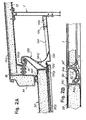
- numeral 1 indicates the fixed platform or fixed floor, which is mounted on longitudinal beams 3 (Fig. 1) and which as a shoe- shaped development in order to make the structure, resting on the ground, slide over same ground for its erection.
- longitudinal beams 3 Fig. 1
- two symmetrical sections 5 of extruded light alloy are applied, each of which make up a cradle for the support and rotation of pultruded elements obtained by pul- trusion, that are made up of glass fiber reinforced polyester.
- Numerals 7, 7A indicate longitudinal structures which connect the two head walls 9 of the rigid assembly; in particular, the structures 7 are joined to the roof or fixed covering 12.
- the covering 12 projects beyond the structures 7 through the part 12A, similarly to the longitudinal edges of the fixed platform provided with sections 5.
- a section 14 is provided for an upper longitudinal edging, which section 14 is a pultruded as well; this section 14 is applied to a metal section 16 solid with the part 12A of the fixed covering; to the section 16, a cradle section 18 is applied for the support and rotation of the corresponding mobile covering.
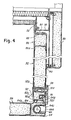
- the head walls 9 extend through lateral parts 9A (see Figs. 4 and 5) provided with vertical columns 20 making part of the central structure; these columns 20 carry vertical hinges 22 applied thereto for the mobile curtain walls.
- a set of mobile panels are provided (Fig. 1) listed as follows; a mobile side floor 26, which is articulated to the cradle 5; a longitudinal wall 28, which is articulated to the outer end of the mobile platform 26 to be lifted thereby; a mobile covering 30 which is articulated to the cradle section 18; and curtain walls 32, which are articulated to the two vertical hinges 22 of the two head walls 9.
- the mobile platform 26 (see Fig. 2C) is provided with a pultruded section 34 capable of cooperating with the cradle section 5 on which it is made to rest.
- a notch 34B adapted to partially receive the cradle profile 5A of the light alloy extruded piece 5.
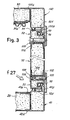
- the mobile platform 26 is formed (see Fig. 3), besides by the section 34, by two side sections 40 each of which has wings 40A for the fastening of said mobile platform to the panel and an appendix 40B forming a profile shaped as an inclined plane, for coupling with the corresponding section of the curtain wall 32.
- an angle bar 42 is provided between the sections 34 and 40, being better illustrated in Figs. 7 to 11 which show it in the various views.
- the angle bar distinctively exhibits a pin 44 intended to provide a constraint against the relative motion between the two sliding cylindrical surfaces 5A and 34A, while the supporting pressures of the mobile platform resting on the fixed platform are assured by the contact between the two sliding cylindrical surfaces of the sections 5 and 34.
- a terminal 46 (Figs. 12, 13) is provided, having a semi-cylindrical seat 46A in correspondence of a right-angle housing 46B to which a block 48 may be fixed, this block being provided as well with a semi-cylindrical seat 48A so as to make up - together with the seat 46A - a seat for the engagement of the pin 44; the block 48 is applied, after the mobile platform has been arranged in the saddle 5A of the section 5, in such a way that the mobile platform 34 is retained by the pin 44 engaged by the block 48 within the seat formed by the two semi-cylindrical seats 46A and 48A. In this way, the constraint between the mobile platform 26 (and in particular its section 34) and the longitudinal edges of the fixed platform 1 is made stable.
- the section 5 For engagement of the section 5 to the fixed platform 1, the latter is provided with a laminar shaped section 1A on which the section 5 is applied through a pair of flanges 5E, 5F of the same section 5, which are inclined to each other for their coupling with the laminar section 1A being steadily engaged to the fixed platform 1.
- the section 34 is provided with flanges 34C for the coupling to the mobile platform 26, with a disposition similar to that of flanges 40A of the section 40 of the same mobile platform 26.
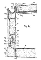
- the mobile platform 26 is delimited by the section 34 for coupling to the fixed platform 1, by the two side sections 40 for coupling to the curtain walls 32, and also by an external section 50 being coupled, by means of flanges 50A, to the same panel 26.
- the section 50 (see Fig. 2) has a box-like structure with an end surface 50B and an extension 50C, which makes up a semi-cylindrical saddle 50E with a stop arcuate terminal 50F, and forms as well a seat for a seal 52.
- the saddle 50E is intended to slidingly couple the longitudinal mobile wall 28 to the mobile platform 26.
- This longitudinal mobile wall 28 has, on the edge, being in the use arrangement in a lower position, a section 54 with flanges 54A for the engagement to the same panel 28 and with a cylindrical, partially convex profile 54B able to slide on the surface of the semi-cylindrical saddle 50E of section 50 of the mobile platform 26.
- the section 54 forms also a wing 54C which represents the extension of the outer surface of the longitudinal mobile wall 28; the wing 54C is able to cooperate with the seal 52 when using the assembly as a house, in the manner clearly visible in Fig. 2.
- the panel of the mobile longitudinal wall 28 is finished, at the edge opposite to that of the section 54, by means of a section 58 with flanges 58A for its engagement to the panel 28 of the longitudinal wall and with a longitudinal channel 58B flanked by a wall 58C provided with a terminal heel 58E.
- a gutter 60 may be received, easily removable from the channel 58B and retained between the sides of this channel and the heel 58E.
- the sections 54 can engage at 50, 50F the sections of the mobile platforms 26.
- the longitudinal wall 28 is delimited, besides by the horizontal sections 54 and 58, by two sections 64 (Fig. 4) which are vertically disposed in the use arrangement, and are provided with flanges 64A for coupling to the panel 28; both sections 64 have a deep channel 64C running vertically developing in the use condition; within said channel 64C a fall pipe 66 - being provided with a diverted exhaust mouth 66A - is housed; advantageously, the channel 64C is opened laterally rather than on the outer front of the longitudinal external mobile wall 28; the fall pipe 66 is joined to the gutter 60 that is housed in the section 58 of the same mobile wall 28.
- Figs. 14 and 17 show an angle bar 70 that is intended to complete the external angle of the mobile floor 26, that is, the connection between the two sections 40 and 50 concurrent to said angle bar 70.
- said angle bar has an appendix 70A making up a retaining side of the section 50; said appendix has a hole 70B which is intended to receive an engagement pin for, preventing relative motion between the two sections 50 and 54 and thus between the mobile platform 26 and the longitudinal wall 28 which, however, rotate on the surface 50E and on the corresponding surface 54B of the section 54.
- Figs. 18,19 and 20 show an angle bar 74, - that is the lower angle bar of the longitudinal wall 28 - which angle bar 74 is applied to the end of section 54 for cooperating with the angle bar 70 (Figs. 15 to 17) provided at the end of the section 50 of the mobile platform 26,
- This angle bar 74 has, in particular, a hole 74B intended to receive a pin which can be inserted, from the outside, either into the hole 74B or into the hole 70B of the angle bar 70, at each end of the mobile channel respectively of the longitudinal mobile wall 28, for engaging these two panels against a relative movement between the slidingly coupled surfaces 54B and 50E.
- the pressure stress between the two panels is discharged along the sliding surfaces 54B and 50E exhibiting a cylindrical profile.
- the angle bar 70 further comprises a seat for a hole 70F provided for the hooking of the metal rope necessary to carry out the operation for rotating the whole panel.
- Figs. 21 to 26 show in various views an angle bar 80 which is developed through a cavity 80A, a wall 80B and a hole 80C, and which has the purpose of connecting the sections 58 and 64 of the longitudinal mobile wall 28 between them.
- the gutter 60 is housed inside the section 58 of the longitudinal wall 28.
- An angle bar 170 (Figs. 40 to 44), included in the angle bar 80, has a joint 170A intended to receive the end of the gutter 60.
- the angle bar 170 - being closed at its end by a wall 170B - provides a terminal bank for said gutter.
- a pipe 170C is joined, which pipe enters the hole 80C and is provided for the fitting of the fall pipe 66.
- a bush 82 is embedded for the screwing of a pin intended to hook the rope by which the rotation for moving the panel 28 from the horizontal position above 26 to the vertical position, is carried out.
- each of the curtain walls 32 is delimited, along the vertical articulation hinge 32, by a section 86 provided with flanges 86A for its coupling to the panel 32 and with plates 88 embedded therein for the engagement of wings 90 which make up the hinge member cooperating with the members 22 fastened to the corresponding section 20.
- each of the panels 32 of the curtain wall is completed by segments of a section (pultruded) 92, which comprises two flanges 92A for the engagement with the panel, a seat 92B for a seal 94 and a right-angle seat 92C for a seal 96; moreover, the section 92 has an appendix 92E shaped as an inclined plane.
- each of the pulltrudeds 92 which form the three- upper, lower and outer - sides of panel 32 of the curtain wall, has a seat for a latch means;
- Fig. 27 shows a detail of that.
- This latch means comprises an outer lever plate 98 which is welded to a shank 100 rotatively housed in a sleeve 102 inserted into the pultruded 92; the shank 100 is axially engaged by a screw stem 140, whose head 106 can be reached from the inside of the dwelling and is received within a flanged glass 108 located in a corresponding hole of the section 92.
- the arrangement is such that the lever 98 may be moved from a position lined up with the section 92 to a position more or less orthogonal therewith, wherein said projecting lever 98 comes in contact with the section 40 of the mobile platform 26, respectively with the vertical sections 64 of the outer longitudinal wall 28, respectively again with the side pulltrudeds of the mobile covering 30 to be described below; under these conditions, the lever 98 may be recalled i.e. returned through the screw means 104,106, thereby forcing the appendixes one towards the other, for instance forcing the appendix 40B or 64B of sections 40 and 64 against the inclined plane appendix 92E of the corresponding section 92, in order to force the concurrent panels one against the other according to an inclined plane, that is, wedged-shaped.
- a similar disposition is provided for the forcing action by the side sections of the mobile covering 30.
- Figs. 28 and 30 show an angle bar 113 which is provided for joining the vertical pultruded element 86 and the upper and inclined pultruded element 92 of a curtain wall 32.
- Figs. 31 to 33 show an angle bar 114 disposed at the opposite side in respect to the angle bar 112 on the upper inclined side of a curtain wall.
- These angle bars 112, 114 exhibit profiles similar to those indicated by 92B and 92C for receiving, without solution of continuity, the two seals 94 and 96 up to the end of the panel.
- These two angle bars are developed with an angle other than 90° and, in particular, smaller than 90° for the angle bar 112 and greater than 90° for the angle bar 114.
- Analogous angle bars located in the lower positions that is, at the ends of the lower side of the curtain wall, are similarto those indicated by 112 and 114, but with an amplitude of exactly 90°; since the angles formed by the curtain panels in the lower part are actually right angles.
- Each of the covering panels 30 has, along the inner edge and articulated to the extension 12A of the fixed covering 12, a finishing section 120 exhibiting flanges 120A for the coupling to the panel 30 and an inclined shaping to end with an articulation nucleus 120B for resting on the cradle bracket 18 fixed to the already described section 16 of the extension 12A,
- the nucleus 120B can slide within the cradle to allow the angular displacement of the mobile covering panel 30 between the use position, being slightly downwards and outwards inclined, and the greatly downwards inclined position resulting close to the main structure (Figs. 2 and 6).
- the section 120 has also a seat 120C which is of use to receive an elastic flashing 122 shaped as shown in the drawing, to complete the ceiling.
- the ceiling is defined - in the use position - by a thickness 30A below the covering panel 30, by the flashing 122 and by a mobile element 124, which is articulated at 126 to a profile 128 being secured to the wall 7 of the fixed main structure; in the use arrangement (Fig. 2), the parts 124, 122 and 30A make up a substantially continuous surface.
- the flashing 122 pushes the element 124 upwards by means of its cusp, thus causing it to rotate around the hinge 128 until the same element 124 takes up the position shown in Fig. 6; the reversed movement causes the flashing 122 to perform an opposite action thereby allowing the lowering of the element 124 until it rests on said flashing in the condition shown in Fig. 2.
- the mobile covering panel 30 is completed at its inclined sides through a section 130 having flanges 130A for the engagement to the same panel 30, and with an appendix 130B (see Fig. 3) which is similar to those indicated by 40B and 64B (see Fig. 4) for cooperating with the appendixes 92E of the upper section of the curtain wall 32 and with its seals 94 and 96.
- Mobile latches like those indicated by 98,108 operate in the same way as already described for the other sides of the curtain walls for the blocking.
- the panel 30 is refined (see Fig.
- Figs. 34, 35 and 36 show one of the angle bars 138 which are intended for fitting the sections 130 to the section 120 at the respective angles of the panel 30.
- the angle bar 138 has an appendix 138A corresponding to the nucleus 120B of the section 120, which appendix 138A makes up a seat 138B for receiving a pin able to engage the mobile covering panel 30 to the section 18, in order to prevent the nucleus 120B from moving away from the cradle of the section 18.
- Figs. 37, 38 and 39 show a further angle bar 140 which connects the two concurrent pulltrudeds 130 and 134 (see Fig. 3) of the mobile covering 30, between them.
- this angle bar 140 has a bush 142 embedded therein along the joint for the section 130, said bush having the purpose to allow the insertion of a pin on which the metal rope - provided for the panel positioning from a horizontal to a vertical position - is to be hooked.
- the mobile covering 130 is slightly lifted above the position of its final arrangement so that the mobile longitudinal wall 28 is able - by moving about the articulation defined by the profiles 50A and 54B - to place itself against the seal 146 by passing below the beak appendix 134B; a slight lowering of the same mobile covering 30 is then provided until the seal 136 rests on the heel 58E of the wall 58C of the upper section 58 of the mobile longitudinal wall 28.
- the seal 144 performs also a second task when the assembly of the mobile components takes up the folding arrangement shown in Fig. 6 under the condition of minimum overall dimensions. Under these conditions, the mobile platform 26, being lifted around the articulation formed by sections 5 and 34, reaches a position below the terminal section t4 of the fixed covering; under these conditions (Fig. 6), the surface 50B of the section 50 of said mobile platform 26 comes into contact and presses on the seal 144 which ensures a substantial sealing action against dust and atmospheric agents thereby protecting what is included between the panel of the mobile platform 26 and the side structure 7, 7A of the main framework of the assembly, namely, the components 28, 30, 32 and the inside of the central structure.
- the seal 52 ensures the sealing between the section 50 and the extension 54C of section 54 in order to seal the mobile platform 26 and the longitudinal vertical mobile wall 28 between each other.
- the seals 96 and 94 provided on the sections 92 on three sides of each of the curtain walls 32, ensures the sealing of the mobile platform 26 with the sections 40, with the section 130 of the covering 30 and with the side vertical sections 64 of the outer longitudinal mobile wall 28.
- a vertical seal - that cooperates with the curtain walls 32 in the opening position - is provided, as shown in Fig. 4, said seal cooperating, instead, with the sections 40 of the mobile platform 26 in the closing condition shown in Fig. 5, thus completing the protective action, together with the seal 144, in the closing conditions of the mobile components against the fixed structure.
- the sections system has been studied to provide also a suitable appearance to the internal surfaces of the rooms delimited by the mobile components peripherically finished by the above described sections.
Landscapes
- Engineering & Computer Science (AREA)
- Architecture (AREA)
- Electromagnetism (AREA)
- Civil Engineering (AREA)
- Structural Engineering (AREA)
- Physics & Mathematics (AREA)
- Building Environments (AREA)
- Finishing Walls (AREA)
- Load-Bearing And Curtain Walls (AREA)
- Curing Cements, Concrete, And Artificial Stone (AREA)
- Transition And Organic Metals Composition Catalysts For Addition Polymerization (AREA)
- Steroid Compounds (AREA)
- Soil Conditioners And Soil-Stabilizing Materials (AREA)
- Tents Or Canopies (AREA)
- Toilet Supplies (AREA)
- Conveying And Assembling Of Building Elements In Situ (AREA)
- Buildings Adapted To Withstand Abnormal External Influences (AREA)
- Compositions Of Macromolecular Compounds (AREA)
- Specific Sealing Or Ventilating Devices For Doors And Windows (AREA)
- Polyurethanes Or Polyureas (AREA)
- Confectionery (AREA)
Abstract
Description
- The invention relates to a transportable structure suitable for building up houses and the like, for immediate intervention in case of calamities and for other uses, comprising a supporting framework made up of closed longitudinal frames, floor plane or platform, roof covering and head walls, all of which delimiting a useful volume, an overturnable paneling, forming the roof covering, being articulated below the roof covering, an overturnable paneling, forming the floor, being articulated to the floor plane of the framework, and an overturnable paneling forming a vertical longitudinal wall being articulated to the floor-forming paneling on the side opposite to the articulation of the latter to the supporting framework; under the transportation and storage conditions, the floor paneling being external and the covering paneling being internal, and under the usage condition, the floor-forming panelings of the additional side volumes resting on legs articulated below the supporting framework to be spaced apart and provided with bearings adjustable on the ground.
- A transportable structure of this type is known from EP-A-0 097 475. It is an object of the invention to improve such structure and particularly to render the articulations between the several panels forming the structure more reliable and wear-resistant. Furthermore, the invention has the object of improving the tightness between the articulated panels in the position ready for use.
- These objects are obtained with a structure of the above mentioned kind, which is characterized in that the mobile panelings are provided with pultruded sections made of reinforced synthetic resin and running along the articulation edges and forming at least part of cylindrical surfaces slidingly cooperating to form the articulations; in that angle joining elements (also referred to as angle bars) located at the ends of said sections form seats for pins able to prevent said cooperating cylindrical surfaces from incidentally moving away from each other or from corresponding cylindrical surfaces formed by cradle sections solid with fixed parts of the framework; in that further angle joining elements are provided for peripherically completing the panels; and in that seals are mounted on the sections for coacting with the sections coupled in the articulations to ensure the sealing.
- Longitudinal articulations between the fixed platform and the mobile platforms may exhibit, in one of the sections, an arcuated appendix and, in the other section, an arcuated seat for said arcuated appendix.
- One of the sections of the longitudinal articulation between the mobile platform and the longitudinal wall may present a surface with a hook stop able to cooperate with a corresponding surface of the section of the longitudinal wall.
- A seal may be provided along each longitudinal edge of the covering, in order to cooperate with the respective mobile covering in the opening condition, and with the external section of the mobile platform in the closing condition.
- Suitable seals may be arranged inwardly of the head walls to cooperate, in the opening condition, with the plugging or curtain walls and, in the closing condition, with the side sections of the mobile platform.
- The mobile covering may be articulated and made to rest through a section provided with an appendix, slidingly supported - for the angular movement - on a cradle. carried by the fixed covering, and a shaped flashing is capable of coacting with a mobile element which is supported to complete the ceiling in the opening condition, and is lifted in the closing condition.
- The invention will be better understood by following the description and the accompanying drawing which shows a practical non limitative exemplification of the same invention. In the drawing:
- Fig. 1 shows an ensemble perspective view in the use condition;
- Figs. 2, 2A, 2B, 2C show a vertical sectional view on line II-II of Fig. 1, that is, according to a plane perpendicular to the longitudinal wall, and three enlarged details indicated by arrows f2A, f2B and f2C;
- Fig. 3 shows a sectional view on line III-III of Fig. 1, that is, according to a vertical plane perpendicular to the plugging that is curtain wall;
- Fig. 4 is a horizontal local sectional view on line IV-IV of Fig. 1, showing the lower part of the curtain wall;
- Fig. 5 is similar to Fig. 4, but showing the components in the closing condition;
- Fig. 6 shows a sectional view similar to that of Fig. 2 but with the components in the closing condition;
- Figs. 7 to 11 show in various views an internal angle bar between the sections of the mobile platform;
- Figs. 12 and 13 show a detail of a cradle- shaped section for the articulation of the mobile platform to the fixed platform, and an enlarged sectional view on line XIII-XIII of Fig. 12;
- Figs. 14, 15, 16, 17 show, in various views and sectional views, an external angle bar between the sections of the mobile platform, with a seat for a pin providing a constraint between the mobile platform and the mobile longitudinal wall;
- Figs. 18, 19, 20 show in two views and in the sectional view on line XX-XX of Fig. 19, a lower angle bar of the longitudinal wall;
- Figs. 21 to 26 show, in various views, an upper angle bar of the longitudinal wall;
- Fig. 27 shows a detail of a section surrounding the curtain wall, with a latch clamping means, as an enlargement of the portion indicated by f27 in Fig. 3;
- Figs. 28 and 30 show an upper angle bar in correspondence of the hinge of a mobile curtain wall articulated to a head wall;
- Figs. 31, 32 and 33 show an upper angle-bar opposite to that of Figs. 28 to 30, on the inclined upper side of a curtain wall;
- Figs. 34 to 36 show in three views an angle bar providing a hinge for the mobile covering;
- Figs. 37 to 39 show in three views an outer angle bar of the mobile covering;
- Figs. 40 to 44 show an angle bar which is used for conveying water.
- In the drawing (Fig. 2), numeral 1 indicates the fixed platform or fixed floor, which is mounted on longitudinal beams 3 (Fig. 1) and which as a shoe- shaped development in order to make the structure, resting on the ground, slide over same ground for its erection. Along the longitudinal edges of the fixed platform 1, two
symmetrical sections 5 of extruded light alloy are applied, each of which make up a cradle for the support and rotation of pultruded elements obtained by pul- trusion, that are made up of glass fiber reinforced polyester.Numerals structures 7 are joined to the roof or fixedcovering 12. The covering 12 projects beyond thestructures 7 through thepart 12A, similarly to the longitudinal edges of the fixed platform provided withsections 5. At the end of each one of theparts 12A of the fixed covering, asection 14 is provided for an upper longitudinal edging, whichsection 14 is a pultruded as well; thissection 14 is applied to ametal section 16 solid with thepart 12A of the fixed covering; to thesection 16, acradle section 18 is applied for the support and rotation of the corresponding mobile covering. - The head walls 9 extend through
lateral parts 9A (see Figs. 4 and 5) provided withvertical columns 20 making part of the central structure; thesecolumns 20 carryvertical hinges 22 applied thereto for the mobile curtain walls. - On each side of the central rigid structure, a set of mobile panels are provided (Fig. 1) listed as follows; a
mobile side floor 26, which is articulated to thecradle 5; alongitudinal wall 28, which is articulated to the outer end of themobile platform 26 to be lifted thereby; amobile covering 30 which is articulated to thecradle section 18; andcurtain walls 32, which are articulated to the twovertical hinges 22 of the two head walls 9. - The mobile platform 26 (see Fig. 2C) is provided with a
pultruded section 34 capable of cooperating with thecradle section 5 on which it is made to rest. The hinge between the fixed platform 1 and themobile platform 26, made up of thecradle section 5 and articulatingsection 34, is developed as acradle 5A formed by the extruded light-alloy piece 5 and by a cylindrical convexpultruded element 34A formed by thepultruded element 34, which has also anotch 34B adapted to partially receive thecradle profile 5A of the light alloy extrudedpiece 5. In this way, when themobile platform 26 is lowered into alignment with the fixed platform 1, an effective sealing is achieved inside the interstice between the two platforms. Themobile platform 26 is formed (see Fig. 3), besides by thesection 34, by twoside sections 40 each of which haswings 40A for the fastening of said mobile platform to the panel and anappendix 40B forming a profile shaped as an inclined plane, for coupling with the corresponding section of thecurtain wall 32. Between thesections angle bar 42 is provided, being better illustrated in Figs. 7 to 11 which show it in the various views. The angle bar distinctively exhibits apin 44 intended to provide a constraint against the relative motion between the two slidingcylindrical surfaces sections pin 44, on each end of thesection 5 of each one of the longitudinal edges of the fixed platform 1, a terminal 46 (Figs. 12, 13) is provided, having asemi-cylindrical seat 46A in correspondence of a right-angle housing 46B to which ablock 48 may be fixed, this block being provided as well with asemi-cylindrical seat 48A so as to make up - together with theseat 46A - a seat for the engagement of thepin 44; theblock 48 is applied, after the mobile platform has been arranged in thesaddle 5A of thesection 5, in such a way that themobile platform 34 is retained by thepin 44 engaged by theblock 48 within the seat formed by the twosemi-cylindrical seats - For engagement of the
section 5 to the fixed platform 1, the latter is provided with a laminarshaped section 1A on which thesection 5 is applied through a pair offlanges same section 5, which are inclined to each other for their coupling with thelaminar section 1A being steadily engaged to the fixed platform 1. - The
section 34 is provided withflanges 34C for the coupling to themobile platform 26, with a disposition similar to that offlanges 40A of thesection 40 of the samemobile platform 26. - The
mobile platform 26 is delimited by thesection 34 for coupling to the fixed platform 1, by the twoside sections 40 for coupling to thecurtain walls 32, and also by anexternal section 50 being coupled, by means offlanges 50A, to thesame panel 26. The section 50 (see Fig. 2) has a box-like structure with an end surface 50B and anextension 50C, which makes up asemi-cylindrical saddle 50E with a stoparcuate terminal 50F, and forms as well a seat for aseal 52. The saddle 50E is intended to slidingly couple the longitudinalmobile wall 28 to themobile platform 26. This longitudinalmobile wall 28 has, on the edge, being in the use arrangement in a lower position, asection 54 withflanges 54A for the engagement to thesame panel 28 and with a cylindrical, partially convexprofile 54B able to slide on the surface of thesemi-cylindrical saddle 50E ofsection 50 of themobile platform 26. Thesection 54 forms also awing 54C which represents the extension of the outer surface of the longitudinalmobile wall 28; thewing 54C is able to cooperate with theseal 52 when using the assembly as a house, in the manner clearly visible in Fig. 2. - The panel of the mobile
longitudinal wall 28 is finished, at the edge opposite to that of thesection 54, by means of asection 58 withflanges 58A for its engagement to thepanel 28 of the longitudinal wall and with alongitudinal channel 58B flanked by awall 58C provided with aterminal heel 58E. Within thechannel 58B agutter 60 may be received, easily removable from thechannel 58B and retained between the sides of this channel and theheel 58E. - The
sections 54 can engage at 50, 50F the sections of themobile platforms 26. - The
longitudinal wall 28 is delimited, besides by thehorizontal sections flanges 64A for coupling to thepanel 28; bothsections 64 have adeep channel 64C running vertically developing in the use condition; within saidchannel 64C a fall pipe 66 - being provided with a divertedexhaust mouth 66A - is housed; advantageously, thechannel 64C is opened laterally rather than on the outer front of the longitudinal externalmobile wall 28; thefall pipe 66 is joined to thegutter 60 that is housed in thesection 58 of the samemobile wall 28. - Figs. 14 and 17 show an
angle bar 70 that is intended to complete the external angle of themobile floor 26, that is, the connection between the twosections angle bar 70. In particular, said angle bar has anappendix 70A making up a retaining side of thesection 50; said appendix has ahole 70B which is intended to receive an engagement pin for, preventing relative motion between the twosections mobile platform 26 and thelongitudinal wall 28 which, however, rotate on thesurface 50E and on thecorresponding surface 54B of thesection 54. - Figs. 18,19 and 20 show an
angle bar 74, - that is the lower angle bar of the longitudinal wall 28 - whichangle bar 74 is applied to the end ofsection 54 for cooperating with the angle bar 70 (Figs. 15 to 17) provided at the end of thesection 50 of themobile platform 26, Thisangle bar 74 has, in particular, ahole 74B intended to receive a pin which can be inserted, from the outside, either into thehole 74B or into thehole 70B of theangle bar 70, at each end of the mobile channel respectively of the longitudinalmobile wall 28, for engaging these two panels against a relative movement between the slidingly coupledsurfaces sliding surfaces angle bar 70 further comprises a seat for ahole 70F provided for the hooking of the metal rope necessary to carry out the operation for rotating the whole panel. - Figs. 21 to 26 show in various views an
angle bar 80 which is developed through acavity 80A, awall 80B and ahole 80C, and which has the purpose of connecting thesections mobile wall 28 between them. Thegutter 60 is housed inside thesection 58 of thelongitudinal wall 28. An angle bar 170 (Figs. 40 to 44), included in theangle bar 80, has a joint 170A intended to receive the end of thegutter 60. The angle bar 170 - being closed at its end by awall 170B - provides a terminal bank for said gutter. To the cavity 170D, apipe 170C is joined, which pipe enters thehole 80C and is provided for the fitting of thefall pipe 66. In correspondence to thehole 80C, abush 82 is embedded for the screwing of a pin intended to hook the rope by which the rotation for moving thepanel 28 from the horizontal position above 26 to the vertical position, is carried out. - Each of the
curtain walls 32 is delimited, along thevertical articulation hinge 32, by asection 86 provided withflanges 86A for its coupling to thepanel 32 and withplates 88 embedded therein for the engagement ofwings 90 which make up the hinge member cooperating with themembers 22 fastened to the correspondingsection 20. On the other three sides, each of thepanels 32 of the curtain wall is completed by segments of a section (pultruded) 92, which comprises twoflanges 92A for the engagement with the panel, aseat 92B for aseal 94 and a right-angle seat 92C for aseal 96; moreover, thesection 92 has anappendix 92E shaped as an inclined plane. At spaced points, each of thepulltrudeds 92 which form the three- upper, lower and outer - sides ofpanel 32 of the curtain wall, has a seat for a latch means; Fig. 27 shows a detail of that. This latch means comprises anouter lever plate 98 which is welded to ashank 100 rotatively housed in asleeve 102 inserted into the pultruded 92; theshank 100 is axially engaged by ascrew stem 140, whosehead 106 can be reached from the inside of the dwelling and is received within aflanged glass 108 located in a corresponding hole of thesection 92. The arrangement is such that thelever 98 may be moved from a position lined up with thesection 92 to a position more or less orthogonal therewith, wherein said projectinglever 98 comes in contact with thesection 40 of themobile platform 26, respectively with thevertical sections 64 of the outerlongitudinal wall 28, respectively again with the side pulltrudeds of themobile covering 30 to be described below; under these conditions, thelever 98 may be recalled i.e. returned through the screw means 104,106, thereby forcing the appendixes one towards the other, for instance forcing theappendix sections inclined plane appendix 92E of the correspondingsection 92, in order to force the concurrent panels one against the other according to an inclined plane, that is, wedged-shaped. A similar disposition is provided for the forcing action by the side sections of themobile covering 30. - Figs. 28 and 30 show an angle bar 113 which is provided for joining the vertical
pultruded element 86 and the upper and inclined pultrudedelement 92 of acurtain wall 32. Figs. 31 to 33 show anangle bar 114 disposed at the opposite side in respect to theangle bar 112 on the upper inclined side of a curtain wall. These angle bars 112, 114 exhibit profiles similar to those indicated by 92B and 92C for receiving, without solution of continuity, the twoseals angle bar 112 and greater than 90° for theangle bar 114. Analogous angle bars located in the lower positions, that is, at the ends of the lower side of the curtain wall, are similarto those indicated by 112 and 114, but with an amplitude of exactly 90°; since the angles formed by the curtain panels in the lower part are actually right angles. - Each of the covering
panels 30 has, along the inner edge and articulated to theextension 12A of the fixed covering 12, afinishing section 120exhibiting flanges 120A for the coupling to thepanel 30 and an inclined shaping to end with anarticulation nucleus 120B for resting on thecradle bracket 18 fixed to the already describedsection 16 of theextension 12A, Thenucleus 120B can slide within the cradle to allow the angular displacement of themobile covering panel 30 between the use position, being slightly downwards and outwards inclined, and the greatly downwards inclined position resulting close to the main structure (Figs. 2 and 6). Thesection 120 has also aseat 120C which is of use to receive anelastic flashing 122 shaped as shown in the drawing, to complete the ceiling. The ceiling is defined - in the use position - by athickness 30A below the coveringpanel 30, by the flashing 122 and by amobile element 124, which is articulated at 126 to aprofile 128 being secured to thewall 7 of the fixed main structure; in the use arrangement (Fig. 2), theparts nucleus 120B oncradle 18, the flashing 122 pushes theelement 124 upwards by means of its cusp, thus causing it to rotate around thehinge 128 until thesame element 124 takes up the position shown in Fig. 6; the reversed movement causes the flashing 122 to perform an opposite action thereby allowing the lowering of theelement 124 until it rests on said flashing in the condition shown in Fig. 2. - The
mobile covering panel 30 is completed at its inclined sides through asection 130 havingflanges 130A for the engagement to thesame panel 30, and with anappendix 130B (see Fig. 3) which is similar to those indicated by 40B and 64B (see Fig. 4) for cooperating with theappendixes 92E of the upper section of thecurtain wall 32 and with itsseals panel 30 is refined (see Fig. 2B) along the side opposite to the one on which thesection 120 is engaged, by means of asection 134 havingflanges 134A, for the assembly on thepanel 30, and a beak-shapedappendix 134B which receives aseal 136 in the bottom of the channel defined by thesame appendix 134B. This beak appendix 134B and theseal 136 are intended to cooperate with theterminal heel 58E of theappendix 58C ofsection 58, thebeak profile 134B makes up a drip for thegutter 60 upon the utilization that is, usage condition shown in Fig. 2. - Figs. 34, 35 and 36 show one of the angle bars 138 which are intended for fitting the
sections 130 to thesection 120 at the respective angles of thepanel 30. In particular, theangle bar 138 has anappendix 138A corresponding to thenucleus 120B of thesection 120, which appendix 138A makes up aseat 138B for receiving a pin able to engage themobile covering panel 30 to thesection 18, in order to prevent thenucleus 120B from moving away from the cradle of thesection 18. - Figs. 37, 38 and 39 show a
further angle bar 140 which connects the twoconcurrent pulltrudeds 130 and 134 (see Fig. 3) of themobile covering 30, between them. In particular, thisangle bar 140 has abush 142 embedded therein along the joint for thesection 130, said bush having the purpose to allow the insertion of a pin on which the metal rope - provided for the panel positioning from a horizontal to a vertical position - is to be hooked. - When the
mobile covering 30 is lifted to the arrangement of Fig. 2, it is caused to press on aseal 144 carried by theend section 14 of the fixed coveringpart mobile covering 30 is made to rest on the vertical longitudinalmobile wall 28, theseal 136 rests on theend heel 58E of thesection 58, thereby ensuring the sealing also in collaboration with afurther seal 146 carried by thesection 134 and acting on the outer surface of thewall 58C of the section 58 (see Fig. 2). In order to reach the use condition, themobile covering 130 is slightly lifted above the position of its final arrangement so that the mobilelongitudinal wall 28 is able - by moving about the articulation defined by theprofiles seal 146 by passing below thebeak appendix 134B; a slight lowering of the same mobile covering 30 is then provided until theseal 136 rests on theheel 58E of thewall 58C of theupper section 58 of the mobilelongitudinal wall 28. In this way, there are obtained both the connection between themobile wall 28 and themobile covering 30 and the sealing by the twoseals appendix 134B in thegutter 60 that discharges same drain in thefall pipe - The
seal 144 performs also a second task when the assembly of the mobile components takes up the folding arrangement shown in Fig. 6 under the condition of minimum overall dimensions. Under these conditions, themobile platform 26, being lifted around the articulation formed bysections section 50 of saidmobile platform 26 comes into contact and presses on theseal 144 which ensures a substantial sealing action against dust and atmospheric agents thereby protecting what is included between the panel of themobile platform 26 and theside structure components - The
seal 52 ensures the sealing between thesection 50 and theextension 54C ofsection 54 in order to seal themobile platform 26 and the longitudinal verticalmobile wall 28 between each other. - The
seals sections 92 on three sides of each of thecurtain walls 32, ensures the sealing of themobile platform 26 with thesections 40, with thesection 130 of the covering 30 and with the sidevertical sections 64 of the outer longitudinalmobile wall 28. - Along the end corners of the
extensions 9A of head walls 9, a vertical seal - that cooperates with thecurtain walls 32 in the opening position - is provided, as shown in Fig. 4, said seal cooperating, instead, with thesections 40 of themobile platform 26 in the closing condition shown in Fig. 5, thus completing the protective action, together with theseal 144, in the closing conditions of the mobile components against the fixed structure. - By the described arrangement of the sections surrounding the various panels, of the seals and of articulations through sliding seats and convex surfaces for the sliding of the mobile panels, many advantages are obtained for rapidity in the industrial assembling and life without alterations, because of the articulations construction, for the possibility of an easy maintenance and for the materials which, at least in part, are utilized for the sections and which are pulltrudeds made up of glass fiber and polyester or other resin, and are actually insensitive to the age alterations and to atmospheric and chemical agents.
- The disposition according to inclined planes of the profiles (like those of
parts 40B; 92E; 64B; 92E; etc) of some of the described sections, in combination with the clamping system by means of screw latches (like those indicated by 98, 108) permits - after the opening of the assembly of the mobile components - a tightening action of the curtain walls against the edges of the panels concurrent to said walls, thus achieving a mechanical rigid stabilization of all the components and ensuring as well, through their seals, the hermetic outward sealing. - The sections system has been studied to provide also a suitable appearance to the internal surfaces of the rooms delimited by the mobile components peripherically finished by the above described sections.
- It is understood that the drawing shows an exemplification given only as a practical demonstration of the invention, as this may vary in the forms and dispositions, without, nevertheless, departing from the scope of the invention as defined in the attached claims.
Claims (6)
Priority Applications (1)
| Application Number | Priority Date | Filing Date | Title |
|---|---|---|---|
| AT86830133T ATE58939T1 (en) | 1985-05-21 | 1986-05-20 | TRANSPORTABLE CONSTRUCTION UNIT, SUITABLE FOR THE CONSTRUCTION OF HOUSES OR OTHER RESIDENCES. |
Applications Claiming Priority (2)
| Application Number | Priority Date | Filing Date | Title |
|---|---|---|---|
| IT941585 | 1985-05-21 | ||
| IT09415/85A IT1201296B (en) | 1985-05-21 | 1985-05-21 | TRANSPORTABLE STRUCTURE IMPROVED, SUITABLE TO CONSTITUTE HOUSES OR OTHER ENVIRONMENTS |
Publications (3)
| Publication Number | Publication Date |
|---|---|
| EP0203043A2 EP0203043A2 (en) | 1986-11-26 |
| EP0203043A3 EP0203043A3 (en) | 1988-03-23 |
| EP0203043B1 true EP0203043B1 (en) | 1990-12-05 |
Family
ID=11129805
Family Applications (1)
| Application Number | Title | Priority Date | Filing Date |
|---|---|---|---|
| EP86830133A Expired - Lifetime EP0203043B1 (en) | 1985-05-21 | 1986-05-20 | Improved transportable structure, apt to build up houses or other dwellings |
Country Status (11)
| Country | Link |
|---|---|
| US (1) | US4726158A (en) |
| EP (1) | EP0203043B1 (en) |
| JP (1) | JPS6225635A (en) |
| AT (1) | ATE58939T1 (en) |
| AU (1) | AU590276B2 (en) |
| CA (1) | CA1290541C (en) |
| DD (1) | DD259218A5 (en) |
| DE (1) | DE3675980D1 (en) |
| DK (1) | DK224486A (en) |
| IL (1) | IL78668A (en) |
| IT (1) | IT1201296B (en) |
Families Citing this family (21)
| Publication number | Priority date | Publication date | Assignee | Title |
|---|---|---|---|---|
| US4891919A (en) * | 1986-12-10 | 1990-01-09 | Palibroda James W | Containerized transportable house |
| FR2612228B1 (en) * | 1987-03-12 | 1992-04-03 | Const Mobiles | BUNGALOW FOUR RAINWATER DRAINAGE SYSTEM |
| GB8723390D0 (en) * | 1987-10-06 | 1987-11-11 | Portakabin Ltd | Erecting modular building |
| JP2510002Y2 (en) * | 1989-03-03 | 1996-09-11 | サンセイアルミ株式会社 | Connection structure of building frame materials |
| DE4020962A1 (en) * | 1990-06-30 | 1992-01-09 | Jodag Mobilsysteme Gmbh | ROOM CELL |
| FR2724400B1 (en) * | 1994-09-09 | 1997-01-31 | Realisations Ind Bureau Et | MOBILE HABITAT |
| GB9503228D0 (en) * | 1995-02-18 | 1995-04-05 | Dyer David C | Modular structures and seals therefor |
| US5815988A (en) * | 1996-06-13 | 1998-10-06 | Molina; Jose Ramon | Expandable retractable portable structure |
| US20030177715A1 (en) * | 2002-03-19 | 2003-09-25 | Dunson Daniel M. | Enclosing system |
| US20060277836A1 (en) * | 2005-05-25 | 2006-12-14 | Fabio Chazyn | Collapsible ISO container-type modular shelter |
| US7418802B2 (en) | 2005-09-09 | 2008-09-02 | Gichner Systems Group, Inc. | Expandable shelter system |
| US20070107321A1 (en) * | 2005-09-09 | 2007-05-17 | Gichner Systems Group, Llc | Expandable shelter system |
| US7930857B2 (en) * | 2008-07-29 | 2011-04-26 | Green Horizon Manufacturing, LLC | Deployable prefabricated structure with an extension structure and a deployable floor |
| US8448403B1 (en) * | 2012-07-09 | 2013-05-28 | David Wallace | Water catchment building block |
| US9109354B2 (en) * | 2013-07-17 | 2015-08-18 | University Of Dayton | Rapid assembly of a modular structure |
| JP3205191U (en) * | 2016-04-28 | 2016-07-07 | 三協フロンテア株式会社 | Pillar frame structure for unit house |
| CN111502016A (en) * | 2016-07-07 | 2020-08-07 | 福州欧冠创新工业设计有限公司 | Mobile house |
| US11109519B2 (en) * | 2019-01-15 | 2021-08-31 | Hdt Expeditionary Systems, Inc. | Mission configurable shelter |
| US11732465B2 (en) * | 2020-05-19 | 2023-08-22 | Pre-Form Systems | System and method for modular construction |
| US20230120060A1 (en) * | 2021-10-15 | 2023-04-20 | GrowTech Industries, LLC | Expandable Portable Shelter and Structures of Multiple Expandable Portable Shelters |
| CN113958044B (en) * | 2021-10-28 | 2022-12-09 | 北京丽贝亚建筑装饰工程有限公司 | Unit type special-shaped perforated aluminum sunshade glass curtain wall structure and installation method thereof |
Family Cites Families (11)
| Publication number | Priority date | Publication date | Assignee | Title |
|---|---|---|---|---|
| US2395691A (en) * | 1942-05-25 | 1946-02-26 | William B Stout | Building with folding walls |
| US3284966A (en) * | 1963-12-05 | 1966-11-15 | Terrapin Overseas Ltd | Collapsible buildings |
| US3348344A (en) * | 1964-02-19 | 1967-10-24 | Tatevossian Leon | Transportable building contruction with an extendable body structure |
| US3633324A (en) * | 1970-04-10 | 1972-01-11 | Belge Atel Reunies | Caravan |
| US3971185A (en) * | 1971-09-09 | 1976-07-27 | Hendrich John H | Method of erecting a foldable building module |
| US3800484A (en) * | 1972-07-20 | 1974-04-02 | R Marshall | Awning for travel trailers and the like |
| SU653362A1 (en) * | 1976-07-21 | 1979-03-25 | Сибирский зональный научно-исследовательский и проектный институт типового и экспериментального проектирования жилых и общественных зданий | Two-storey three-dimensional collapsible unit |
| GB2077321A (en) * | 1980-05-29 | 1981-12-16 | Cuthbert James David Rollo | Cabin building |
| FR2495205A1 (en) * | 1980-12-02 | 1982-06-04 | Technal France | Adjustable structure for supporting roofing frameworks - comprises at least two complementary profiles within cooperating cylinder and socket arrangement acting as hinge |
| EP0116817A1 (en) * | 1982-04-28 | 1984-08-29 | Petrus Jozef Minner | Camping-device to be mounted on a vehicle |
| IT1192455B (en) * | 1982-06-18 | 1988-04-13 | Giovanna Maria Fagnoni | TRANSPORTABLE STRUCTURE TO FORM A HOUSE OR OTHER, SUITABLE FOR IMMEDIATE INTERVENTIONS |
-
1985
- 1985-05-21 IT IT09415/85A patent/IT1201296B/en active
-
1986
- 1986-05-02 IL IL78668A patent/IL78668A/en not_active IP Right Cessation
- 1986-05-12 JP JP61106906A patent/JPS6225635A/en active Pending
- 1986-05-14 DK DK224486A patent/DK224486A/en not_active Application Discontinuation
- 1986-05-19 US US06/865,162 patent/US4726158A/en not_active Expired - Fee Related
- 1986-05-20 DD DD86290389A patent/DD259218A5/en not_active IP Right Cessation
- 1986-05-20 EP EP86830133A patent/EP0203043B1/en not_active Expired - Lifetime
- 1986-05-20 AT AT86830133T patent/ATE58939T1/en not_active IP Right Cessation
- 1986-05-20 CA CA000509476A patent/CA1290541C/en not_active Expired - Fee Related
- 1986-05-20 DE DE8686830133T patent/DE3675980D1/en not_active Expired - Fee Related
- 1986-05-21 AU AU57633/86A patent/AU590276B2/en not_active Ceased
Also Published As
| Publication number | Publication date |
|---|---|
| AU590276B2 (en) | 1989-11-02 |
| DK224486A (en) | 1986-11-22 |
| IL78668A0 (en) | 1986-08-31 |
| CA1290541C (en) | 1991-10-15 |
| DE3675980D1 (en) | 1991-01-17 |
| DD259218A5 (en) | 1988-08-17 |
| DK224486D0 (en) | 1986-05-14 |
| EP0203043A2 (en) | 1986-11-26 |
| EP0203043A3 (en) | 1988-03-23 |
| US4726158A (en) | 1988-02-23 |
| ATE58939T1 (en) | 1990-12-15 |
| IT1201296B (en) | 1989-01-27 |
| IL78668A (en) | 1990-04-29 |
| JPS6225635A (en) | 1987-02-03 |
| IT8509415A0 (en) | 1985-05-21 |
| AU5763386A (en) | 1986-11-27 |
Similar Documents
| Publication | Publication Date | Title |
|---|---|---|
| EP0203043B1 (en) | Improved transportable structure, apt to build up houses or other dwellings | |
| US4534141A (en) | Transportable pre-fabricated building structure | |
| US6883273B2 (en) | Hydraulically operated overhead door | |
| US7631460B2 (en) | Transportable building | |
| EP0428589B1 (en) | Connection system | |
| US7134243B2 (en) | Blast resistant window framework and elements thereof | |
| BRPI0719354A2 (en) | FOLDING INDOOR | |
| JP6679754B2 (en) | Assembly for prefabricated container house system | |
| CN111663652A (en) | Rapid house | |
| CA2215661C (en) | Modular structures | |
| EP0951609B1 (en) | A window, in particular for mounting in an inclined roof surface | |
| GB2037838A (en) | A Foldable Prefabricated Building Structure | |
| US4996802A (en) | Snap fit building structure | |
| JPH11270239A (en) | Sliding door structure for partition | |
| KR100337519B1 (en) | collapsible house container | |
| CN214696093U (en) | Folding box house frame section bar | |
| JP7133334B2 (en) | Simple structure | |
| CN218758911U (en) | Box-type room entrance to a cave faces limit protector | |
| RU2160349C1 (en) | Set of sections for external translucent building envelopes | |
| JPH0953288A (en) | Mounting construction of curtain wall unit and mullion bearing the curtain wall unit and joint construction of transom | |
| JP3810869B2 (en) | Entrance fence unit and its mounting method | |
| JP2664855B2 (en) | Bay window mounting structure | |
| JPS6313343Y2 (en) | ||
| GB2160239A (en) | Building system | |
| GB2378455A (en) | Framework connectors |
Legal Events
| Date | Code | Title | Description |
|---|---|---|---|
| PUAI | Public reference made under article 153(3) epc to a published international application that has entered the european phase |
Free format text: ORIGINAL CODE: 0009012 |
|
| AK | Designated contracting states |
Kind code of ref document: A2 Designated state(s): AT BE CH DE FR GB LI LU NL SE |
|
| PUAL | Search report despatched |
Free format text: ORIGINAL CODE: 0009013 |
|
| AK | Designated contracting states |
Kind code of ref document: A3 Designated state(s): AT BE CH DE FR GB LI LU NL SE |
|
| 17P | Request for examination filed |
Effective date: 19880415 |
|
| 17Q | First examination report despatched |
Effective date: 19890908 |
|
| GRAA | (expected) grant |
Free format text: ORIGINAL CODE: 0009210 |
|
| AK | Designated contracting states |
Kind code of ref document: B1 Designated state(s): AT BE CH DE FR GB LI LU NL SE |
|
| REF | Corresponds to: |
Ref document number: 58939 Country of ref document: AT Date of ref document: 19901215 Kind code of ref document: T |
|
| BECN | Be: change of holder's name |
Effective date: 19901205 |
|
| REF | Corresponds to: |
Ref document number: 3675980 Country of ref document: DE Date of ref document: 19910117 |
|
| RAP2 | Party data changed (patent owner data changed or rights of a patent transferred) |
Owner name: SICIT S.P.A. |
|
| ET | Fr: translation filed | ||
| PLBE | No opposition filed within time limit |
Free format text: ORIGINAL CODE: 0009261 |
|
| STAA | Information on the status of an ep patent application or granted ep patent |
Free format text: STATUS: NO OPPOSITION FILED WITHIN TIME LIMIT |
|
| 26N | No opposition filed | ||
| PGFP | Annual fee paid to national office [announced via postgrant information from national office to epo] |
Ref country code: DE Payment date: 19940513 Year of fee payment: 9 |
|
| PGFP | Annual fee paid to national office [announced via postgrant information from national office to epo] |
Ref country code: FR Payment date: 19940516 Year of fee payment: 9 Ref country code: GB Payment date: 19940516 Year of fee payment: 9 |
|
| PGFP | Annual fee paid to national office [announced via postgrant information from national office to epo] |
Ref country code: SE Payment date: 19940518 Year of fee payment: 9 |
|
| PGFP | Annual fee paid to national office [announced via postgrant information from national office to epo] |
Ref country code: BE Payment date: 19940520 Year of fee payment: 9 |
|
| PGFP | Annual fee paid to national office [announced via postgrant information from national office to epo] |
Ref country code: AT Payment date: 19940524 Year of fee payment: 9 |
|
| PGFP | Annual fee paid to national office [announced via postgrant information from national office to epo] |
Ref country code: CH Payment date: 19940526 Year of fee payment: 9 |
|
| PGFP | Annual fee paid to national office [announced via postgrant information from national office to epo] |
Ref country code: NL Payment date: 19940531 Year of fee payment: 9 Ref country code: LU Payment date: 19940531 Year of fee payment: 9 |
|
| EPTA | Lu: last paid annual fee | ||
| EAL | Se: european patent in force in sweden |
Ref document number: 86830133.4 |
|
| PG25 | Lapsed in a contracting state [announced via postgrant information from national office to epo] |
Ref country code: LU Free format text: LAPSE BECAUSE OF NON-PAYMENT OF DUE FEES Effective date: 19950520 Ref country code: GB Effective date: 19950520 Ref country code: AT Effective date: 19950520 |
|
| PG25 | Lapsed in a contracting state [announced via postgrant information from national office to epo] |
Ref country code: SE Effective date: 19950521 |
|
| PG25 | Lapsed in a contracting state [announced via postgrant information from national office to epo] |
Ref country code: LI Effective date: 19950531 Ref country code: CH Effective date: 19950531 Ref country code: BE Effective date: 19950531 |
|
| BERE | Be: lapsed |
Owner name: SICIT S.P.A. Effective date: 19950531 |
|
| PG25 | Lapsed in a contracting state [announced via postgrant information from national office to epo] |
Ref country code: NL Effective date: 19951201 |
|
| GBPC | Gb: european patent ceased through non-payment of renewal fee |
Effective date: 19950520 |
|
| REG | Reference to a national code |
Ref country code: CH Ref legal event code: PL |
|
| NLV4 | Nl: lapsed or anulled due to non-payment of the annual fee |
Effective date: 19951201 |
|
| PG25 | Lapsed in a contracting state [announced via postgrant information from national office to epo] |
Ref country code: DE Effective date: 19960201 |
|
| EUG | Se: european patent has lapsed |
Ref document number: 86830133.4 |
|
| PG25 | Lapsed in a contracting state [announced via postgrant information from national office to epo] |
Ref country code: FR Effective date: 19960229 |
|
| REG | Reference to a national code |
Ref country code: FR Ref legal event code: ST |
|
| REG | Reference to a national code |
Ref country code: FR Ref legal event code: ST |