EP0202767B1 - Symmetrical fault current detector - Google Patents
Symmetrical fault current detector Download PDFInfo
- Publication number
- EP0202767B1 EP0202767B1 EP86302854A EP86302854A EP0202767B1 EP 0202767 B1 EP0202767 B1 EP 0202767B1 EP 86302854 A EP86302854 A EP 86302854A EP 86302854 A EP86302854 A EP 86302854A EP 0202767 B1 EP0202767 B1 EP 0202767B1
- Authority
- EP
- European Patent Office
- Prior art keywords
- current
- detector
- signal
- capacitors
- rectifier
- Prior art date
- Legal status (The legal status is an assumption and is not a legal conclusion. Google has not performed a legal analysis and makes no representation as to the accuracy of the status listed.)
- Expired - Lifetime
Links
- 239000003990 capacitor Substances 0.000 claims abstract description 17
- 230000004044 response Effects 0.000 claims abstract description 8
- 238000007599 discharging Methods 0.000 claims description 2
- 230000005669 field effect Effects 0.000 claims description 2
- 230000001960 triggered effect Effects 0.000 claims description 2
- 239000004020 conductor Substances 0.000 abstract description 4
- 230000015556 catabolic process Effects 0.000 abstract 1
- 238000001514 detection method Methods 0.000 description 5
- 230000009118 appropriate response Effects 0.000 description 1
- 230000001419 dependent effect Effects 0.000 description 1
- 238000010586 diagram Methods 0.000 description 1
- 230000000694 effects Effects 0.000 description 1
- 230000005611 electricity Effects 0.000 description 1
- 238000012544 monitoring process Methods 0.000 description 1
- 238000009877 rendering Methods 0.000 description 1
- 238000004804 winding Methods 0.000 description 1
Images
Classifications
-
- H—ELECTRICITY
- H02—GENERATION; CONVERSION OR DISTRIBUTION OF ELECTRIC POWER
- H02H—EMERGENCY PROTECTIVE CIRCUIT ARRANGEMENTS
- H02H3/00—Emergency protective circuit arrangements for automatic disconnection directly responsive to an undesired change from normal electric working condition with or without subsequent reconnection ; integrated protection
- H02H3/08—Emergency protective circuit arrangements for automatic disconnection directly responsive to an undesired change from normal electric working condition with or without subsequent reconnection ; integrated protection responsive to excess current
Definitions
- the present invention is concerned with the detection of fault currents in electricity power lines. It is a common practice for electrical power systems to be equipped with means for detecting excessive currents so that faulty parts of the power system can be automatically isolated. Such devices may be over current relays or sectionalisers (such as that disclosed in our patent application no. 8215641). Excessive current can be detected by any means that recognises that the magnitude of the current in the power system has exceeded a given threshold value.
- a problem with existing fault and over current detection systems is that they are prone to be actuated in response to short term current excursions which may occur in a normal healthy power system.
- a particular problem is that resulting from transformer magnetising inrush currents which occur when a section of the distribution system is energised resulting in the energising of one or more distribution transformers.
- former current detection devices have typically been set with their threshold values sufficiently high to ensure that transformer magnetising inrush currents do not actuate them. Such threshold values may then be considerably higher than the ideal threshold value which would be chosen to detect all fault currents if transformer magnetising inrush currents were not a problem. As a result the overall protection of the power system is sometimes not as good as would be desirable.
- Current protection relay systems are known (see US-A-4443854) which include a current transformer to provide a signal representative of current flowing in an alternating current power line and have means responsive to said signal to provide a fault current indication only if the alternating current flow represents by said signal exceeds a predetermined threshold in each polarity. It is further known (see US-A-2316289) to respond independently to the current flow in half-cycles of respective polarity of the supply waveform and to provide a respective indication of the flow in each polarity exceeding a predetermined threshold.
- the means responsive to the current transformer signal in a fault current detector of the above known kind comprises a full wave rectifier rectifying the output signal of the current transformer means, a resistance connected across the output terminals of the rectifier and a respective threshold switch connected to each input terminal of the rectifier and arranged to be triggered in response to the voltage between the respective input terminal and a common output terminal of the rectifier exceeding a predetermined threshold voltage.
- a current transformer 2 is illustrated monitoring the current flowing in an electrical supply line or conductor 1.
- the secondary winding of the current transformer 2 is connected to the input terminals of a full wave bridge rectifier 3.
- the output terminals of the bridge rectifier 3 are connected across a resistor 4.
- One output terminal of the bridge rectifier 3 is connected to a common line 20.
- One of the input terminals of the bridge rectifier 3 is also connected by means of a resistor 5 in series with a bi-directional trigger diode 7, a diode 9 and a capacitor 14, to the common line 20.
- the other input of the bridge rectifier 3 is connected by means of a resistor 6 in series with a bi-directional trigger diode 8, a diode 10 and a capacitor 13 also to the common line 20.
- the trigger diodes 7 and 8 are devices which break down to present a low impedance to current in the event of a voltage across the trigger diode in excess of a predetermined threshold. The trigger diodes recover automatically once the current through them drops to zero.
- the circuit operates as follows.
- the value of the resistor 4 across the output terminals of the bridge rectifier 3 is selected so that the voltage across the resistor exceeds the break down voltage of the trigger diodes 7 and 8, when the current in any half-cycle of the mains waveform in the power conductor 1 exceeds a desirable maximum level.
- the capacitors 13 and 14 are discharged so that substantially the full voltage drop across the resistor 4 is developed across each of the trigger diodes 7 and 8 on respective alternate half-cycles of the mains supply.
- a respective one of the trigger diodes 7 and 8 breaks down, depending on the polarity of the supply waveform.
- Lines 21 and 22 from the capacitors 14 and 13 respectively supply logic signals representative of the state of charge of these capacitors to a control logic unit 23.
- the control logic unit 23 is arranged to monitor the logic state on line 21 and 22 and to provide a fault indication only if both lines 21 and 22 are in states indicative of excessive current excursions in both polarities of the supply waveform. If only one of lines 21 and 22 indicates an excessive current excursion, it is assumed that this is due to a magnetising inrush current and the control logic 23 is arranged not to provide a fault indication.
- the circuit may be reset by discharging the capacitors 13 and 14. This is achieved by a reset signal on line 24 from the control logic unit which makes a power field effect transistor 16 conducting thereby to short circuit the two capacitors 13 and 14 via respective diodes 12 and 11 and the resistor 15.
- the reset line 24 is controlled to keep the transistor 16 non-conducting.
- the control logic unit 23 can provide control signals on line 25 for operating circuit breakers, sectionalisers, etc. in the usual way in response to detection of a fault current.
- the control logic will respond to only one of lines 21 and 22 indicating an excessive current of only one polarity, by generating a reset signal on line 24 to reset the capacitors.
- the control logic unit effects an appropriate response, e.g. to isolate the supply line, and subsequently resets the detector circuit as before.
- the current transformer 2 need not be a high quality protection current transformer. It is only necessary for the transformer 2 to provide sufficient energy output in response to an over current, to drive the voltage across the resistor 4 above the trigger threshold voltage of the diodes 7 and 8. Provided the current transformer 2 provides sufficient energy for this purpose, it does not matter if a small transformer is used which magnetically saturates.
- the circuit illustrated in the attached drawing is only an example of possible circuits which can embody the present invention.
- the trigger diodes 7 and 8 may be replaced by any other appropriate means of switching in response to a voltage exceeding a threshold voltage.
- the described example and other embodiments of the invention may be particularly useful when used in an automatic sectionaliser as part of the over current detection circuit, thereby rendering the sectionaliser more sensitive to actual (symmetrical) fault currents but insensitive to magnetising inrush currents.
Landscapes
- Emergency Protection Circuit Devices (AREA)
- Testing Of Short-Circuits, Discontinuities, Leakage, Or Incorrect Line Connections (AREA)
- Measuring Instrument Details And Bridges, And Automatic Balancing Devices (AREA)
- Control Of Motors That Do Not Use Commutators (AREA)
- Control Of Electric Motors In General (AREA)
- Interface Circuits In Exchanges (AREA)
- Monitoring And Testing Of Exchanges (AREA)
Abstract
Description
- The present invention is concerned with the detection of fault currents in electricity power lines. It is a common practice for electrical power systems to be equipped with means for detecting excessive currents so that faulty parts of the power system can be automatically isolated. Such devices may be over current relays or sectionalisers (such as that disclosed in our patent application no. 8215641). Excessive current can be detected by any means that recognises that the magnitude of the current in the power system has exceeded a given threshold value.
- A problem with existing fault and over current detection systems is that they are prone to be actuated in response to short term current excursions which may occur in a normal healthy power system. A particular problem is that resulting from transformer magnetising inrush currents which occur when a section of the distribution system is energised resulting in the energising of one or more distribution transformers. Former current detection devices have typically been set with their threshold values sufficiently high to ensure that transformer magnetising inrush currents do not actuate them. Such threshold values may then be considerably higher than the ideal threshold value which would be chosen to detect all fault currents if transformer magnetising inrush currents were not a problem. As a result the overall protection of the power system is sometimes not as good as would be desirable.
- Current protection relay systems are known (see US-A-4443854) which include a current transformer to provide a signal representative of current flowing in an alternating current power line and have means responsive to said signal to provide a fault current indication only if the alternating current flow represents by said signal exceeds a predetermined threshold in each polarity. It is further known (see US-A-2316289) to respond independently to the current flow in half-cycles of respective polarity of the supply waveform and to provide a respective indication of the flow in each polarity exceeding a predetermined threshold.
- In accordance with the present invention, the means responsive to the current transformer signal in a fault current detector of the above known kind comprises a full wave rectifier rectifying the output signal of the current transformer means, a resistance connected across the output terminals of the rectifier and a respective threshold switch connected to each input terminal of the rectifier and arranged to be triggered in response to the voltage between the respective input terminal and a common output terminal of the rectifier exceeding a predetermined threshold voltage.
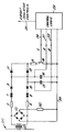
- An example of the invention will now be described with reference to the accompanying drawing which is a circuit diagram of a fault current detector embodying the present invention.
- Referring to the drawing, a current transformer 2 is illustrated monitoring the current flowing in an electrical supply line or
conductor 1. The secondary winding of the current transformer 2 is connected to the input terminals of a fullwave bridge rectifier 3. The output terminals of thebridge rectifier 3 are connected across a resistor 4. One output terminal of thebridge rectifier 3 is connected to acommon line 20. One of the input terminals of thebridge rectifier 3 is also connected by means of aresistor 5 in series with abi-directional trigger diode 7, a diode 9 and a capacitor 14, to thecommon line 20. Similarly, the other input of thebridge rectifier 3 is connected by means of aresistor 6 in series with a bi-directional trigger diode 8, adiode 10 and acapacitor 13 also to thecommon line 20. - The
trigger diodes 7 and 8 are devices which break down to present a low impedance to current in the event of a voltage across the trigger diode in excess of a predetermined threshold. The trigger diodes recover automatically once the current through them drops to zero. - The circuit operates as follows. The value of the resistor 4 across the output terminals of the
bridge rectifier 3 is selected so that the voltage across the resistor exceeds the break down voltage of thetrigger diodes 7 and 8, when the current in any half-cycle of the mains waveform in thepower conductor 1 exceeds a desirable maximum level. Initially, thecapacitors 13 and 14 are discharged so that substantially the full voltage drop across the resistor 4 is developed across each of thetrigger diodes 7 and 8 on respective alternate half-cycles of the mains supply. In the event that the supply current in any particular half-cycle exceeds the desired maximum, so that the voltage across the resistor 4 exceeds the switching threshold, a respective one of thetrigger diodes 7 and 8 breaks down, depending on the polarity of the supply waveform. When the trigger breaks down, current flows through the respectiveforward bias diode 9 or 10 to charge up therespective capacitor 14 or 13. It can be seen, therefore, that a respective one of thecapacitors 14 and 13 is charged dependent on the polarity of the half-cycle of the supply waveform which exceeds the switching threshold. -
Lines capacitors 14 and 13 respectively supply logic signals representative of the state of charge of these capacitors to acontrol logic unit 23. Thecontrol logic unit 23 is arranged to monitor the logic state online lines lines control logic 23 is arranged not to provide a fault indication. - Referring again to the drawing, the circuit may be reset by discharging the
capacitors 13 and 14. This is achieved by a reset signal online 24 from the control logic unit which makes a power field effect transistor 16 conducting thereby to short circuit the twocapacitors 13 and 14 viarespective diodes 12 and 11 and the resistor 15. When the circuit is in normal operation awaiting a fault current, thereset line 24 is controlled to keep the transistor 16 non-conducting. - The
control logic unit 23 can provide control signals online 25 for operating circuit breakers, sectionalisers, etc. in the usual way in response to detection of a fault current. In normal operation, the control logic will respond to only one oflines line 24 to reset the capacitors. In response to bothlines - It can be seen that electrical connections may be made to any point of the circuit of the drawing for the purpose of making timing and synchronisation information available to the
control logic 23. Further, it may be appreciated that the current transformer 2 need not be a high quality protection current transformer. It is only necessary for the transformer 2 to provide sufficient energy output in response to an over current, to drive the voltage across the resistor 4 above the trigger threshold voltage of thediodes 7 and 8. Provided the current transformer 2 provides sufficient energy for this purpose, it does not matter if a small transformer is used which magnetically saturates. - The circuit illustrated in the attached drawing is only an example of possible circuits which can embody the present invention. The
trigger diodes 7 and 8 may be replaced by any other appropriate means of switching in response to a voltage exceeding a threshold voltage. - The described example and other embodiments of the invention may be particularly useful when used in an automatic sectionaliser as part of the over current detection circuit, thereby rendering the sectionaliser more sensitive to actual (symmetrical) fault currents but insensitive to magnetising inrush currents.
Claims (6)
- A fault current detector comprising current transformer means (2) to provide a signal representative of current flowing in an alternating current power line and means responsive to said signal to provide a fault current indication only if the alternating current flow represented by said signal exceeds a predetermined threshold in each polarity wherein said means responsive to said signal is independently responsive to the current flow in half-cycles of respective polarity of the supply waveform and provides a respective indication of the flow in each polarity exceeding a predetermined threshold characterised in that said means responsive to said signal comprises a full wave rectifier (3) rectifying the output signal of the current transformer means (2), a resistance (4) connected across the output terminals of the rectifier (3) and a respective threshold switch (7,8) connected to each input terminal of the rectifier (3) and arranged to be triggered in response to the voltage between the respective input terminal and a common output terminal of the rectifier exceeding a predetermined threshold voltage.
- A detector as claimed in Claim 1 wherein each of the respective threshold switches (7,8) comprises a bi-directional trigger diode connected in series with a diode (9,10) and a capacitor (14,13) to a common line (20) connected to the common output terminal of the rectifier (3).
- A detector as claimed in Claim 2 including respective lines (21,22) from the capacitors (14,13) to supply logic signals representative of the state of charge of the capacitors to a control logic unit (23) arranged to monitor the logic state on said lines (21,22) to provide a fault indication only if both of said lines are in states indicative of excessive current excursions in both polarities of the supply waveform.
- A detector as claimed in Claim 2 or 3 including means for resetting the circuit by discharging the capacitors.
- A detector as claimed in Claim 3 wherein a reset signal is produced on a reset line (24) from the control logic unit (23) which makes a power field effect transistor (16) conducting thereby to short circuit said capacitors (14,13) via respective diodes (11,12) and a resistor (15).
- A detector as claimed in Claim 5, wherein the control logic unit (23) is arranged to respond to only one of said respective lines (21,22) from the capacitors indicating an excessive current of only one polarity, by generating a reset signal on said reset line (24).
Priority Applications (1)
| Application Number | Priority Date | Filing Date | Title |
|---|---|---|---|
| AT86302854T ATE82441T1 (en) | 1985-05-20 | 1986-04-16 | BALANCED FAULT CURRENT DETECTOR. |
Applications Claiming Priority (2)
| Application Number | Priority Date | Filing Date | Title |
|---|---|---|---|
| GB8512746 | 1985-05-20 | ||
| GB08512746A GB2175469B (en) | 1985-05-20 | 1985-05-20 | Symmetrical fault current detector |
Publications (3)
| Publication Number | Publication Date |
|---|---|
| EP0202767A2 EP0202767A2 (en) | 1986-11-26 |
| EP0202767A3 EP0202767A3 (en) | 1988-01-20 |
| EP0202767B1 true EP0202767B1 (en) | 1992-11-11 |
Family
ID=10579413
Family Applications (1)
| Application Number | Title | Priority Date | Filing Date |
|---|---|---|---|
| EP86302854A Expired - Lifetime EP0202767B1 (en) | 1985-05-20 | 1986-04-16 | Symmetrical fault current detector |
Country Status (8)
| Country | Link |
|---|---|
| US (2) | US4797775A (en) |
| EP (1) | EP0202767B1 (en) |
| AT (1) | ATE82441T1 (en) |
| BR (1) | BR8602235A (en) |
| CA (1) | CA1287110C (en) |
| DE (1) | DE3687084T2 (en) |
| GB (1) | GB2175469B (en) |
| ZA (1) | ZA863230B (en) |
Families Citing this family (3)
| Publication number | Priority date | Publication date | Assignee | Title |
|---|---|---|---|---|
| US5117325A (en) * | 1990-01-23 | 1992-05-26 | Cooper Industries, Inc. | Controllable recloser for power line |
| US9702910B2 (en) | 2013-08-26 | 2017-07-11 | Micropac Industries, Inc. | Power controller |
| CN112867928B (en) | 2018-07-17 | 2024-09-17 | 哈勃股份有限公司 | Voltage collector for power distribution system |
Family Cites Families (9)
| Publication number | Priority date | Publication date | Assignee | Title |
|---|---|---|---|---|
| US2316289A (en) * | 1941-08-29 | 1943-04-13 | Per N Sandstrom | Current responsive protective relay system |
| DE1463006C3 (en) * | 1963-09-10 | 1974-10-17 | Calor-Emag Elktrizitaets-Aktiengesellschaft, 4030 Ratingen | Trip device for a current-limiting switchgear |
| US3956670A (en) * | 1973-01-30 | 1976-05-11 | Westinghouse Electric Corporation | Circuit interrupter circuit including improved control |
| US3962606A (en) * | 1974-10-09 | 1976-06-08 | General Signal Corporation | Sensor for a ground fault circuit interrupter |
| US4443854A (en) * | 1981-06-08 | 1984-04-17 | Electric Power Research Institute, Inc. | Current sensor responsive to symmetrical and asymmetrical currents and current limiting protector utilizing same |
| FR2520165B1 (en) * | 1982-01-18 | 1986-02-07 | Claude Sa | DIFFERENTIAL SWITCH FOR DOMESTIC USE |
| US4454557A (en) * | 1982-04-15 | 1984-06-12 | Mcgraw-Edison Company | Non-linear alternating current transducer |
| GB2120876B (en) * | 1982-05-28 | 1985-11-06 | Electricty Council The | Sectionaliser |
| US4583004A (en) * | 1983-09-22 | 1986-04-15 | Solidstate Controls, Inc. | Current monitoring circuit for static switch of uninterruptable power system |
-
1985
- 1985-05-20 GB GB08512746A patent/GB2175469B/en not_active Expired
-
1986
- 1986-04-16 AT AT86302854T patent/ATE82441T1/en not_active IP Right Cessation
- 1986-04-16 DE DE8686302854T patent/DE3687084T2/en not_active Expired - Fee Related
- 1986-04-16 EP EP86302854A patent/EP0202767B1/en not_active Expired - Lifetime
- 1986-04-21 US US06/854,246 patent/US4797775A/en not_active Ceased
- 1986-04-30 ZA ZA863230A patent/ZA863230B/en unknown
- 1986-05-02 CA CA000508184A patent/CA1287110C/en not_active Expired - Fee Related
- 1986-05-16 BR BR8602235A patent/BR8602235A/en unknown
-
1991
- 1991-03-12 US US07/668,101 patent/USRE34163E/en not_active Expired - Fee Related
Also Published As
| Publication number | Publication date |
|---|---|
| DE3687084T2 (en) | 1993-04-08 |
| GB2175469B (en) | 1988-10-26 |
| AU595797B2 (en) | 1990-04-12 |
| AU5651886A (en) | 1986-11-27 |
| GB2175469A (en) | 1986-11-26 |
| ZA863230B (en) | 1986-12-30 |
| EP0202767A3 (en) | 1988-01-20 |
| GB8512746D0 (en) | 1985-06-26 |
| US4797775A (en) | 1989-01-10 |
| DE3687084D1 (en) | 1992-12-17 |
| BR8602235A (en) | 1987-01-13 |
| USRE34163E (en) | 1993-01-19 |
| CA1287110C (en) | 1991-07-30 |
| EP0202767A2 (en) | 1986-11-26 |
| ATE82441T1 (en) | 1992-11-15 |
Similar Documents
| Publication | Publication Date | Title |
|---|---|---|
| US4879624A (en) | Power controller | |
| US5889643A (en) | Apparatus for detecting arcing faults and ground faults in multiwire branch electric power circuits | |
| US5825599A (en) | Ground fault circuit interrupter system with uncommitted contacts | |
| CA2181491C (en) | Ground fault circuit interrupt system including auxiliary surge suppression ability | |
| US3611035A (en) | Ground fault protective system having grounded neutral protection | |
| US6014297A (en) | Apparatus for detecting arcing faults and ground faults in multiwire branch electric power circuits | |
| CN101227076B (en) | Fault self-checking circuit of earthing fault breaker | |
| US4363064A (en) | Overcurrent protection system | |
| US4380785A (en) | Solid state trip unit for an electrical circuit breaker | |
| JPH05501043A (en) | Loss of neutral or ground protection circuit | |
| US4812943A (en) | Current fault protection system | |
| US4421976A (en) | System for monitoring heater elements of electric furnaces | |
| US4466041A (en) | Fault protection system for power supplies that use ferro-resonant transformers | |
| US3895263A (en) | Grounded neutral detector drive circuit for two pole ground fault interrupter | |
| US4375660A (en) | Ground isolation monitoring apparatus having a protective circuit | |
| US3838314A (en) | Detector for reverse and open phase in a three phase circuit | |
| US3723815A (en) | Electronic circuit protective device | |
| GB2224404A (en) | Residual current device with missing neutral protection | |
| US3277342A (en) | Overload sensing circuit for line type modulator | |
| US4045822A (en) | Ground fault interrupter apparatus | |
| EP0202767B1 (en) | Symmetrical fault current detector | |
| GB2215149A (en) | Ground fault current interrupter with open neutral/ground lead operation | |
| GB1572457A (en) | Fault detecting and indicating apparatus | |
| US3617809A (en) | Electronic safety system | |
| US3609458A (en) | Electronic safety system |
Legal Events
| Date | Code | Title | Description |
|---|---|---|---|
| PUAI | Public reference made under article 153(3) epc to a published international application that has entered the european phase |
Free format text: ORIGINAL CODE: 0009012 |
|
| AK | Designated contracting states |
Kind code of ref document: A2 Designated state(s): AT BE CH DE FR LI NL SE |
|
| PUAL | Search report despatched |
Free format text: ORIGINAL CODE: 0009013 |
|
| AK | Designated contracting states |
Kind code of ref document: A3 Designated state(s): AT BE CH DE FR LI NL SE |
|
| 17P | Request for examination filed |
Effective date: 19880421 |
|
| 17Q | First examination report despatched |
Effective date: 19900402 |
|
| RAP1 | Party data changed (applicant data changed or rights of an application transferred) |
Owner name: ELECTRICITY ASSOCIATION SERVICES LIMITED |
|
| GRAA | (expected) grant |
Free format text: ORIGINAL CODE: 0009210 |
|
| AK | Designated contracting states |
Kind code of ref document: B1 Designated state(s): AT BE CH DE FR LI NL SE |
|
| PG25 | Lapsed in a contracting state [announced via postgrant information from national office to epo] |
Ref country code: SE Effective date: 19921111 Ref country code: AT Effective date: 19921111 |
|
| REF | Corresponds to: |
Ref document number: 82441 Country of ref document: AT Date of ref document: 19921115 Kind code of ref document: T |
|
| REF | Corresponds to: |
Ref document number: 3687084 Country of ref document: DE Date of ref document: 19921217 |
|
| ET | Fr: translation filed | ||
| PLBI | Opposition filed |
Free format text: ORIGINAL CODE: 0009260 |
|
| 26 | Opposition filed |
Opponent name: SIEMENS AG Effective date: 19930730 |
|
| NLR1 | Nl: opposition has been filed with the epo |
Opponent name: SIEMENS AG |
|
| PGFP | Annual fee paid to national office [announced via postgrant information from national office to epo] |
Ref country code: CH Payment date: 19940225 Year of fee payment: 9 |
|
| PGFP | Annual fee paid to national office [announced via postgrant information from national office to epo] |
Ref country code: BE Payment date: 19940307 Year of fee payment: 9 |
|
| PGFP | Annual fee paid to national office [announced via postgrant information from national office to epo] |
Ref country code: FR Payment date: 19940330 Year of fee payment: 9 |
|
| PGFP | Annual fee paid to national office [announced via postgrant information from national office to epo] |
Ref country code: NL Payment date: 19940430 Year of fee payment: 9 |
|
| PGFP | Annual fee paid to national office [announced via postgrant information from national office to epo] |
Ref country code: DE Payment date: 19940622 Year of fee payment: 9 |
|
| REG | Reference to a national code |
Ref country code: FR Ref legal event code: TP |
|
| NLS | Nl: assignments of ep-patents |
Owner name: EA TECHNOLOGY LIMITED TE CAPENHURST, GROOT-BRITTAN |
|
| PG25 | Lapsed in a contracting state [announced via postgrant information from national office to epo] |
Ref country code: LI Effective date: 19950430 Ref country code: CH Effective date: 19950430 Ref country code: BE Effective date: 19950430 |
|
| BERE | Be: lapsed |
Owner name: EA TECHNOLOGY LTD Effective date: 19950430 |
|
| PG25 | Lapsed in a contracting state [announced via postgrant information from national office to epo] |
Ref country code: NL Effective date: 19951101 |
|
| REG | Reference to a national code |
Ref country code: CH Ref legal event code: PL |
|
| PG25 | Lapsed in a contracting state [announced via postgrant information from national office to epo] |
Ref country code: FR Effective date: 19951229 |
|
| NLV4 | Nl: lapsed or anulled due to non-payment of the annual fee |
Effective date: 19951101 |
|
| PG25 | Lapsed in a contracting state [announced via postgrant information from national office to epo] |
Ref country code: DE Effective date: 19960103 |
|
| PLBO | Opposition rejected |
Free format text: ORIGINAL CODE: EPIDOS REJO |
|
| REG | Reference to a national code |
Ref country code: FR Ref legal event code: ST |
|
| PLBN | Opposition rejected |
Free format text: ORIGINAL CODE: 0009273 |
|
| STAA | Information on the status of an ep patent application or granted ep patent |
Free format text: STATUS: OPPOSITION REJECTED |
|
| 27O | Opposition rejected |
Effective date: 19960108 |
|
| APAH | Appeal reference modified |
Free format text: ORIGINAL CODE: EPIDOSCREFNO |