EP0202756B1 - Protection apparatus - Google Patents
Protection apparatus Download PDFInfo
- Publication number
- EP0202756B1 EP0202756B1 EP86302734A EP86302734A EP0202756B1 EP 0202756 B1 EP0202756 B1 EP 0202756B1 EP 86302734 A EP86302734 A EP 86302734A EP 86302734 A EP86302734 A EP 86302734A EP 0202756 B1 EP0202756 B1 EP 0202756B1
- Authority
- EP
- European Patent Office
- Prior art keywords
- phase
- characteristic
- relay
- line
- fault
- Prior art date
- Legal status (The legal status is an assumption and is not a legal conclusion. Google has not performed a legal analysis and makes no representation as to the accuracy of the status listed.)
- Expired
Links
Images

Classifications
-
- H—ELECTRICITY
- H02—GENERATION; CONVERSION OR DISTRIBUTION OF ELECTRIC POWER
- H02H—EMERGENCY PROTECTIVE CIRCUIT ARRANGEMENTS
- H02H3/00—Emergency protective circuit arrangements for automatic disconnection directly responsive to an undesired change from normal electric working condition with or without subsequent reconnection ; integrated protection
- H02H3/40—Emergency protective circuit arrangements for automatic disconnection directly responsive to an undesired change from normal electric working condition with or without subsequent reconnection ; integrated protection responsive to ratio of voltage and current
Definitions
- This invention relates to electric power transmission system protection apparatus.
- Such apparatuses frequently employ so-called distance relays to determine whether a fault on the system is within a predetermined distance of a monitoring point where the relay is located.
- the present invention is particularly concerned with distance relays which respond to single phase to ground faults, a separate such relay being normally provided for each phase of polyphase power transmission system.
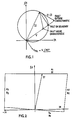
- the quantities V-IZ and V are necessarily at 90°, and hence the quantities V-IZ and V Pol are necessarily in phase when the meeting point of the vectors V and V-IZ lies on a circle having IZ as diameter, by determining, using a phase comparator, whether V-IZ leads or lags V Pol it can be determined whether the fault is beyond or within the distance for which the tip of the vector V lies on the circle.
- the top or “reactance" line of the quadrilateral is defined by a comparator which determines the relative phase of quantities A 1 and 8 1 which are chosen according to the required slope and position of the line.
- the right hand “resistance” line of the quadrilateral is defined by a comparator responsive to quantities A 2 and B 2
- the left hand “resistance” line of the quadrilateral is defined by a comparator responsive to quantities A3 and 8a
- the bottom "directional" line of the quadrilateral is defined by a comparator responsive to quantities A4 and B 4 .
- a distance relay for indicating single phase to ground faults in a polyphase electric power transmission system, the relay having a first guard zone quadrilateral characteristic in respect of each phase of the system and a second main quadrilateral characteristic in respect of each phase of the system, the relay indicating the presence of a fault on a single phase to ground within the reach of the main characteristic relating to the relevant phase only if the corresponding guard zone characteristic, and no other, indicates a fault, and the reactance line of each guard zone characteristic being arranged to change its slope under two-phase to ground fault conditions by a lesser amount than the reactance line of the corresponding main characteristic.
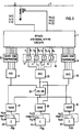
- the relay is intended to provide an output when a fault to ground appears on any one of the phases of a three-phase power transmission line 1, within a predetermined direction and distance of the point on the line 1 at which the relay is located.
- the relay includes currents transformers 3 which produce signals l a (t), I b lt) and l c (t) respectively representing the phase currents at the relay location, and voltage transformers 5 which produce signals V . (t), V b (t) and V b (t) respectively representing the phase voltages at the relay location.
- the signals l a (t), V.(t) etc. are fed to signal mixing and replica impedance circuits 7 wherein the various voltages required for application to phase comparators incorporated in the relay are produced.
- the relay includes a unit 17, 18 or 19 comprising four high speed comparators 9, 11, 13 and 15 which together define a guard zone quadrilateral characteristic.
- the four comparators 9, 11, 13 and 15 for one unit 18 only are shown, the comparator units for the other two phases each being indicated by a single box 17 or 19.
- Each of the comparators 9 to 15 is of the kind which operates in response to squared-up versions A and B of the relevant input signals, which thus convey only phase angle information of the original signals.
- the comparators treat the input square waves A and B as logic variables and after each change in state in either input signal provide a logic output indicating whether that change of state was consistent with A leading B by 0° to 180° or with B leading A by 0° to 180°, i.e. the sequence of inputs A and B.
- Such a comparator is described in United Kingdom Patent Specification No. 1,547,360 and US Patent Specification No. 4,104,586.
- the four comparators 9, 11, 13 and 15 respectively define the top or "reactance" line 21 of the quadrilateral characteristic, the right-hand and left-hand or “resistance” lines 23 and 25 of the characteristic, and the bottom or “directional” line 27 of the characteristic.
- the comparator 9 compares signals A, and B 1 , where and where V PH and I PH are the relevant phase voltage and current, IN is the neutral current, Z PH and Z N are replica phase and neutral impedances and R is a replica fault resistance determining the setting of the relay.
- the values of the replica impedances and resistance are chosen so that the top line is set at a position corresponding to about twice the reach actually required for the relay.
- the comparator 11 compares signals A 2 and 8 2 where
- the comparator 13 compares signals A3 and B 3 where
- the comparator 15 compares signals A4 and B 4 where where V Pol is a partially cross-polarised voltage derived in known manner.
- the outputs of the comparators 9, 11, 13 and 15 are applied to an AND circuit 29 so that a logic '1' appears at the output of the circuit 29 only when the sequence of the pair of signals applied to each of the four comparators is consistent with the fault lying within the guard zone quadrilateral characteristic, i.e. only when the fault is at a distance such that the tip of the relevant phase voltage V PH lies within the characteristic.
- the outputs of the three AND gates 29, 31 and 33 are applied to respective inputs of an exclusive OR gate 35 so that a logic'1' appears at the output of gate 35 only if only one and no other of the AND gates 29, 31 and 33 has a logic'1' at its output, i.e. only if there is a fault to ground on one phase only of the system within the reach defined by the guard zone quadrilateral characteristics.
- the output of the exclusive OR gate 35 is applied to one input of each of three two-input NAND gates 37, 39 and 41 to whose other inputs the outputs of the AND gates 29, 31 and 33 are respectively applied.
- the outputs of the NAND gates 37, 39 and 41 are thus necessarily all at logic'1' when more than one phase has a ground fault within the guard zone, and when a ground fault within the guard zone is present on one phase only, the output of only the relevant one of the NAND gates assumes a logic '0'.
- the outputs of the NAND gates 37, 39 and 41 respectively control the operation of three further comparators 43, 45 and 47 which respectively define for each phase a further reactance line, as indicated by line 49 in Figure 4, which sets the actual reach required for the relay.
- each comparator 43, 45 and 47 compares signals As and B 5 where It will be appreciated that the signal 8 5 is chosen so as to optimise performance of the relay under single phase to ground fault conditions.
- Each of the comparators 43, 45 and 47 produces after each change of state of either of its inputs a signal indicating the sequence of its inputs, as described above with reference to comparators 9 to 15. For each such change of state, when this signal indicates the required sequence the count of a counter is incremented by one, and the presence of a fault is indicated at the output of the comparator 43, 45 or 47 when the count reaches a predetermined value.
- the output of the associated NAND gate 37, 39 or 41 is at logic'1' the counting is inhibited, counting proceeding only when the associated NAND gate output is at logic '0'.
- the logic used to derive the inhibit signals for the comparators 43, 45 and 47 is such that an output can appear at the output of a comparator 43, 45 or 47 only when a fault is within the reach of the corresponding main quadrilateral characteristic and within the reach of the corresponding guard zone quadrilateral characteristic and no other.
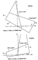
- the top lines (49, Figure 4) of the main quadrilateral characteristics change slope in such a sense that the main characteristic corresponding to the leading one of the two grounded phases underreaches and the main characteristic corresponding to the lagging one of the two grounded phases overreaches.
- line 51 indicates the new position of the top line of the main characteristic corresponding to the leading phase a
- line 53 indicates the new position of the top line of the main characteristic corresponding to the lagging phase b for a phases a to b to ground fault approximately 30% outside the desired reach for single phase faults.
Landscapes
- Emergency Protection Circuit Devices (AREA)
Description
- This invention relates to electric power transmission system protection apparatus.
- Such apparatuses frequently employ so-called distance relays to determine whether a fault on the system is within a predetermined distance of a monitoring point where the relay is located. The present invention is particularly concerned with distance relays which respond to single phase to ground faults, a separate such relay being normally provided for each phase of polyphase power transmission system.
- In a well-known form of such a relay the determination is made by comparing the phases of voltages derived from measurements of the system voltage and current at the monitoring point under fault conditions. For example, referring to Figure 1, in the so-called mho characteristic relay the phases of quantities V-IZ and VPol are compared where:-
- V is the phase voltage at the monitoring point;
- I is the phase current at the monitoring point;
- Z is a replica impedance which determines the setting of the relay i.e. the predetermined distance or reach: and
- vPol is v∠-90°.
- Since the quantities V-IZ and V are necessarily at 90°, and hence the quantities V-IZ and VPol are necessarily in phase when the meeting point of the vectors V and V-IZ lies on a circle having IZ as diameter, by determining, using a phase comparator, whether V-IZ leads or lags VPol it can be determined whether the fault is beyond or within the distance for which the tip of the vector V lies on the circle.
- Whilst such a relay has many applications, it suffers from the disadvantage that its reach depends on the impedance presented by the fault, and in particular, decreases significantly for faults with a high resistance e.g. such as may occur for faults near the monitoring point when the ground contact resistance is high or the lines of the system are supported on towers with high footing resistance.
- To overcome this problem it is known (see e.g. Siemens Energietechnik, vol. 1, No. 4, 1979, pages 153-156, DE; G. Ziegler: "Mehrsystemiger Distanzschutz fur Hochstspannungsnetze") to use a distance relay having a quadrilateral characteristic such as that shown in Figure 2. With this relay each side of the quadrilateral characteristic is independently defined by a separate phase comparator, the four sides together defining the reach of the relay in the same way as the circle defines the reach of a mho characteristic relay.
- Thus the top or "reactance" line of the quadrilateral is defined by a comparator which determines the relative phase of quantities A1 and 81 which are chosen according to the required slope and position of the line. Similarly the right hand "resistance" line of the quadrilateral is defined by a comparator responsive to quantities A2 and B2 the left hand "resistance" line of the quadrilateral is defined by a comparator responsive to quantities A3 and 8a and the bottom "directional" line of the quadrilateral is defined by a comparator responsive to quantities A4 and B4.
- One difficulty which arises with a quadrilateral characteristic relay is that if the relay is optimised for single-phase to ground fault operation, when a two-phase to ground fault occurs the top side, i.e. reactance line, of the characteristic changes slope causing the relay to overreach or underreach.
- To overcome this problem it has been proposed that the single phase to ground phase comparators be blocked from operation if a phase to phase fault comparator or a two-phase to ground fault comparator indicates a fault. However, this suffers from so-called 'race' problems, i.e. it necessarily requires the phase to phase fault comparator to indicate a fault first for satisfactory operation.
- It is an object of the present invention to provide a distance relay for single phase to ground faults having a quadrilateral characteristic which employs a novel method of overcoming the above-mentioned problem which arises on the occurrence of two-phase to ground faults.
- According to the present invention there is provided a distance relay for indicating single phase to ground faults in a polyphase electric power transmission system, the relay having a first guard zone quadrilateral characteristic in respect of each phase of the system and a second main quadrilateral characteristic in respect of each phase of the system, the relay indicating the presence of a fault on a single phase to ground within the reach of the main characteristic relating to the relevant phase only if the corresponding guard zone characteristic, and no other, indicates a fault, and the reactance line of each guard zone characteristic being arranged to change its slope under two-phase to ground fault conditions by a lesser amount than the reactance line of the corresponding main characteristic.
- One distance relay for single-phase to ground faults in accordance with the invention will now be described, by way of example, with reference to the accompanying drawings in which:
- Figure 3 is a block schematic diagram of the relay;
- Figure 4 is a diagram illustrating the operation of the relay under single-phase to ground fault conditions; and
- Figures 5a and 5b are diagrams illustrating the operation of the relay under two-phase to ground fault conditions for a fault approximately 30% outside the reach for single phase faults.
- Referring to Figure 3, the relay is intended to provide an output when a fault to ground appears on any one of the phases of a three-phase
power transmission line 1, within a predetermined direction and distance of the point on theline 1 at which the relay is located. - The relay includes
currents transformers 3 which produce signals la(t), Iblt) and lc(t) respectively representing the phase currents at the relay location, andvoltage transformers 5 which produce signals V.(t), Vb(t) and Vb(t) respectively representing the phase voltages at the relay location. - The signals la(t), V.(t) etc. are fed to signal mixing and
replica impedance circuits 7 wherein the various voltages required for application to phase comparators incorporated in the relay are produced. - In respect of each phase of the
line 1 the relay includes aunit high speed comparators comparators unit 18 only are shown, the comparator units for the other two phases each being indicated by asingle box 17 or 19. - Each of the comparators 9 to 15 is of the kind which operates in response to squared-up versions A and B of the relevant input signals, which thus convey only phase angle information of the original signals. The comparators treat the input square waves A and B as logic variables and after each change in state in either input signal provide a logic output indicating whether that change of state was consistent with A leading B by 0° to 180° or with B leading A by 0° to 180°, i.e. the sequence of inputs A and B. Such a comparator is described in United Kingdom Patent Specification No. 1,547,360 and US Patent Specification No. 4,104,586.
- Referring now to Figure 4, the four
comparators line 21 of the quadrilateral characteristic, the right-hand and left-hand or "resistance"lines line 27 of the characteristic. To this end the comparator 9 compares signals A, and B1, where

- As is further explained below the values of the replica impedances and resistance are chosen so that the top line is set at a position corresponding to about twice the reach actually required for the relay.
- The
comparator 11 compares signals A2 and 82 where -


comparator 13 compares signals A3 and B3 where

- The
comparator 15 compares signals A4 and B4 where

- The outputs of the
comparators AND circuit 29 so that a logic '1' appears at the output of thecircuit 29 only when the sequence of the pair of signals applied to each of the four comparators is consistent with the fault lying within the guard zone quadrilateral characteristic, i.e. only when the fault is at a distance such that the tip of the relevant phase voltage VPH lies within the characteristic. - The outputs of the four
comparators 17 or 19 for the other two phases are similarly all applied to anAND gate - The outputs of the three AND
gates gate 35 so that a logic'1' appears at the output ofgate 35 only if only one and no other of theAND gates - The output of the exclusive OR
gate 35 is applied to one input of each of three two-input NAND gates AND gates - The outputs of the
NAND gates - The outputs of the
NAND gates further comparators line 49 in Figure 4, which sets the actual reach required for the relay. - To this end each
comparator 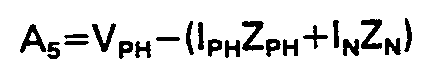

- Each of the
comparators comparator associated NAND gate - It will thus be seen that in operation of the relay, when a fault occurs to ground on a single phase of the line, an output can appear only at the output of the relevant one of the
comparators comparator comparators corresponding unit - The logic used to derive the inhibit signals for the
comparators comparator - Hence, when a two-phase to ground fault occurs the operation of all three of the
comparators comparators 9, 11 13 and 15. - When a two-phase to ground fault occurs, the top lines (49, Figure 4) of the main quadrilateral characteristics change slope in such a sense that the main characteristic corresponding to the leading one of the two grounded phases underreaches and the main characteristic corresponding to the lagging one of the two grounded phases overreaches. This is indicated in Figure 5a where line 51 indicates the new position of the top line of the main characteristic corresponding to the leading phase a and in Figure 5b where
line 53 indicates the new position of the top line of the main characteristic corresponding to the lagging phase b for a phases a to b to ground fault approximately 30% outside the desired reach for single phase faults. - In Figures 5a and 5b the apparent tilting of the characteristics is due to residual compensation applied which is chosen to be correct for single phase faults.
- If the top lines (21, Figure 4) of the guard zone quadrilateral characteristics similarly changed slope, then the possibility would arise that the relay would indicate a ground fault on the lagging one of the two grounded phases.
- The likelihood of this is reduced by virtue of the fact that the polarising voltages B used for the
top lines 21 of the guard zone quadrilateral characteristics involve a phase current component. In consequence, theselines 21 change their slope by a lesser amount than thetop lines 49 of the main quadrilateral characteristics, as indicated byline 55 in Figure 5a andline 57 in Figure 5b. - Hence a fault such as that indicated by x in Figures 5a and 5b which is within the reach of both main and guard overreaching b -G characteristics, does not cause operation of the relay since it is also within the reach of the underreaching a -G guard characteristic even although it is not within the reach of the underreaching a -G main characteristic.
- It will be appreciated that as a result of including a phase current component in the 81 inputs of the guard zone comparators 9, the input B, is non optimum for single phase faults and the top line may consequently droop under load exporting conditions. However, by making the guard zone reach appreciably greater than the main characteristics reach, underreach of the relay due to this cause is avoided.
- It will be appreciated that in a protection apparatus using a distance relay in accordance with the invention indication of two-phase to ground faults will be carried out by further comparator arrangements dedicated to the detection of two-phase to ground faults and arranged to be practically independent of fault resistance to ground.
Claims (8)
Applications Claiming Priority (4)
| Application Number | Priority Date | Filing Date | Title |
|---|---|---|---|
| GB8509858 | 1985-04-17 | ||
| GB858509858A GB8509858D0 (en) | 1985-04-17 | 1985-04-17 | Protection apparatus |
| GB8521306 | 1985-08-27 | ||
| GB858521306A GB8521306D0 (en) | 1985-08-27 | 1985-08-27 | Protection apparatus |
Publications (2)
| Publication Number | Publication Date |
|---|---|
| EP0202756A1 EP0202756A1 (en) | 1986-11-26 |
| EP0202756B1 true EP0202756B1 (en) | 1990-09-12 |
Family
ID=26289137
Family Applications (1)
| Application Number | Title | Priority Date | Filing Date |
|---|---|---|---|
| EP86302734A Expired EP0202756B1 (en) | 1985-04-17 | 1986-04-14 | Protection apparatus |
Country Status (6)
| Country | Link |
|---|---|
| US (1) | US4706156A (en) |
| EP (1) | EP0202756B1 (en) |
| AU (1) | AU594261B2 (en) |
| DE (1) | DE3674062D1 (en) |
| GB (1) | GB2173963B (en) |
| IN (1) | IN166184B (en) |
Families Citing this family (11)
| Publication number | Priority date | Publication date | Assignee | Title |
|---|---|---|---|---|
| US5121282A (en) * | 1990-03-30 | 1992-06-09 | White Orval C | Arcing fault detector |
| US5434509A (en) * | 1992-07-30 | 1995-07-18 | Blades; Frederick K. | Method and apparatus for detecting arcing in alternating-current power systems by monitoring high-frequency noise |
| US5432455A (en) * | 1992-07-30 | 1995-07-11 | Blades; Frederick K. | Method and apparatus for detecting arcing in alternating current power systems by monitoring high-frequency noise |
| US5223795A (en) * | 1992-07-30 | 1993-06-29 | Blades Frederick K | Method and apparatus for detecting arcing in electrical connections by monitoring high frequency noise |
| DE19605025C2 (en) * | 1996-01-31 | 2003-06-18 | Siemens Ag | Distance protection method |
| GB2345810B (en) * | 1999-01-13 | 2003-07-23 | Alstom Uk Ltd | Fault-detection apparatus |
| US6239959B1 (en) | 1999-06-30 | 2001-05-29 | General Electric Company | Ground distance relay for AC power transmission line protection |
| US6734370B2 (en) * | 2001-09-07 | 2004-05-11 | Irvine Sensors Corporation | Multilayer modules with flexible substrates |
| US8675327B2 (en) * | 2007-03-30 | 2014-03-18 | General Electric Company | Fast impedance protection technique immune to dynamic errors of capacitive voltage transformers |
| US8072715B2 (en) * | 2008-07-16 | 2011-12-06 | Huntington Ingalls Incorporated | Method, apparatus and computer program product for fault protection |
| AT519450B1 (en) * | 2017-02-09 | 2018-07-15 | Sprecher Automation Gmbh | Method for controlling a distance protection relay by detecting conductor-earth faults |
Family Cites Families (4)
| Publication number | Priority date | Publication date | Assignee | Title |
|---|---|---|---|---|
| US4293886A (en) * | 1979-12-17 | 1981-10-06 | Westinghouse Electric Corp. | Network protector relay |
| US4377833A (en) * | 1981-08-17 | 1983-03-22 | Electric Power Research Institute, Inc. | Methods and apparatus for protecting electrical reactors |
| US4405966A (en) * | 1981-10-07 | 1983-09-20 | General Electric Company | System for providing protection for a high voltage transmission line |
| US4433353A (en) * | 1982-07-29 | 1984-02-21 | General Electric Company | Positive sequence undervoltage distance relay |
-
1986
- 1986-04-10 US US06/850,134 patent/US4706156A/en not_active Expired - Fee Related
- 1986-04-14 GB GB08609076A patent/GB2173963B/en not_active Expired
- 1986-04-14 EP EP86302734A patent/EP0202756B1/en not_active Expired
- 1986-04-14 DE DE8686302734T patent/DE3674062D1/en not_active Expired - Lifetime
- 1986-04-16 AU AU56195/86A patent/AU594261B2/en not_active Ceased
- 1986-04-17 IN IN343/DEL/86A patent/IN166184B/en unknown
Also Published As
| Publication number | Publication date |
|---|---|
| IN166184B (en) | 1990-03-24 |
| US4706156A (en) | 1987-11-10 |
| AU594261B2 (en) | 1990-03-01 |
| EP0202756A1 (en) | 1986-11-26 |
| DE3674062D1 (en) | 1990-10-18 |
| GB2173963A (en) | 1986-10-22 |
| GB2173963B (en) | 1988-06-29 |
| GB8609076D0 (en) | 1986-05-21 |
| AU5619586A (en) | 1986-10-23 |
Similar Documents
| Publication | Publication Date | Title |
|---|---|---|
| US5956220A (en) | Adaptive distance protection system | |
| US4841405A (en) | Protective relaying apparatus for providing fault-resistance correction | |
| US5796258A (en) | Adaptive quadrilateral characteristic distance relay | |
| US5694281A (en) | Zero sequence voltage-polarized directional element for protective relays | |
| US6590397B2 (en) | Line differential protection system for a power transmission line | |
| Roberts et al. | Directional element design and evaluation | |
| EP0202756B1 (en) | Protection apparatus | |
| US4686601A (en) | Ground distance relay for AC power transmission line protection | |
| EP0316204B1 (en) | Protective relay | |
| EP0076697B1 (en) | Protection system for high voltage transmission lines | |
| US5838525A (en) | High speed single-pole trip logic for use in protective relaying | |
| EP0151565B1 (en) | Phase relay for ac power transmission line protection | |
| Mooney et al. | Application guidelines for ground fault protection | |
| US4450497A (en) | Ultra-high-speed relay | |
| EP0319151B1 (en) | Circuit to prevent uncontrolled tripping of a protective relay | |
| Alexander et al. | Ground distance relaying: Problems and principles | |
| US4249124A (en) | Method and apparatus for monitoring faults by means of a polygonal trigger region | |
| US2393983A (en) | Relay | |
| US4536815A (en) | Protective relay apparatus and method for providing single-pole tripping | |
| US4296451A (en) | Ultra high speed protective relay circuit | |
| EP4009460A1 (en) | Method and system for detecting faults in a low voltage three-phase network | |
| Alexander et al. | Effects of load flow on relay performance | |
| JP2796455B2 (en) | Ground fault phase determination device | |
| Calero et al. | Identifying the proper impedance plane and fault trajectories in distance protection analysis | |
| JPS6240925B2 (en) |
Legal Events
| Date | Code | Title | Description |
|---|---|---|---|
| PUAI | Public reference made under article 153(3) epc to a published international application that has entered the european phase |
Free format text: ORIGINAL CODE: 0009012 |
|
| AK | Designated contracting states |
Kind code of ref document: A1 Designated state(s): CH DE FR LI SE |
|
| 17P | Request for examination filed |
Effective date: 19870403 |
|
| 17Q | First examination report despatched |
Effective date: 19890823 |
|
| RAP1 | Party data changed (applicant data changed or rights of an application transferred) |
Owner name: GEC ALSTHOM LIMITED |
|
| GRAA | (expected) grant |
Free format text: ORIGINAL CODE: 0009210 |
|
| AK | Designated contracting states |
Kind code of ref document: B1 Designated state(s): CH DE FR LI SE |
|
| ET | Fr: translation filed | ||
| REF | Corresponds to: |
Ref document number: 3674062 Country of ref document: DE Date of ref document: 19901018 |
|
| PLBE | No opposition filed within time limit |
Free format text: ORIGINAL CODE: 0009261 |
|
| STAA | Information on the status of an ep patent application or granted ep patent |
Free format text: STATUS: NO OPPOSITION FILED WITHIN TIME LIMIT |
|
| 26N | No opposition filed | ||
| PGFP | Annual fee paid to national office [announced via postgrant information from national office to epo] |
Ref country code: SE Payment date: 19930316 Year of fee payment: 8 |
|
| PGFP | Annual fee paid to national office [announced via postgrant information from national office to epo] |
Ref country code: FR Payment date: 19930330 Year of fee payment: 8 |
|
| PGFP | Annual fee paid to national office [announced via postgrant information from national office to epo] |
Ref country code: CH Payment date: 19930423 Year of fee payment: 8 |
|
| PGFP | Annual fee paid to national office [announced via postgrant information from national office to epo] |
Ref country code: DE Payment date: 19930626 Year of fee payment: 8 |
|
| PG25 | Lapsed in a contracting state [announced via postgrant information from national office to epo] |
Ref country code: SE Effective date: 19940415 |
|
| PG25 | Lapsed in a contracting state [announced via postgrant information from national office to epo] |
Ref country code: LI Effective date: 19940430 Ref country code: CH Effective date: 19940430 |
|
| PG25 | Lapsed in a contracting state [announced via postgrant information from national office to epo] |
Ref country code: FR Effective date: 19941229 |
|
| REG | Reference to a national code |
Ref country code: CH Ref legal event code: PL |
|
| PG25 | Lapsed in a contracting state [announced via postgrant information from national office to epo] |
Ref country code: DE Effective date: 19950103 |
|
| EUG | Se: european patent has lapsed |
Ref document number: 86302734.8 Effective date: 19941110 |
|
| REG | Reference to a national code |
Ref country code: FR Ref legal event code: ST |