EP0202747A2 - Improvements in or relating to video image creation systems - Google Patents
Improvements in or relating to video image creation systems Download PDFInfo
- Publication number
- EP0202747A2 EP0202747A2 EP86302545A EP86302545A EP0202747A2 EP 0202747 A2 EP0202747 A2 EP 0202747A2 EP 86302545 A EP86302545 A EP 86302545A EP 86302545 A EP86302545 A EP 86302545A EP 0202747 A2 EP0202747 A2 EP 0202747A2
- Authority
- EP
- European Patent Office
- Prior art keywords
- signals
- store
- video
- brush
- image
- Prior art date
- Legal status (The legal status is an assumption and is not a legal conclusion. Google has not performed a legal analysis and makes no representation as to the accuracy of the status listed.)
- Withdrawn
Links
Images


Classifications
-
- G—PHYSICS
- G06—COMPUTING OR CALCULATING; COUNTING
- G06F—ELECTRIC DIGITAL DATA PROCESSING
- G06F3/00—Input arrangements for transferring data to be processed into a form capable of being handled by the computer; Output arrangements for transferring data from processing unit to output unit, e.g. interface arrangements
- G06F3/01—Input arrangements or combined input and output arrangements for interaction between user and computer
- G06F3/048—Interaction techniques based on graphical user interfaces [GUI]
- G06F3/0484—Interaction techniques based on graphical user interfaces [GUI] for the control of specific functions or operations, e.g. selecting or manipulating an object, an image or a displayed text element, setting a parameter value or selecting a range
- G06F3/04845—Interaction techniques based on graphical user interfaces [GUI] for the control of specific functions or operations, e.g. selecting or manipulating an object, an image or a displayed text element, setting a parameter value or selecting a range for image manipulation, e.g. dragging, rotation, expansion or change of colour
-
- G—PHYSICS
- G06—COMPUTING OR CALCULATING; COUNTING
- G06T—IMAGE DATA PROCESSING OR GENERATION, IN GENERAL
- G06T11/00—Two-dimensional [2D] image generation
- G06T11/10—Texturing; Colouring; Generation of textures or colours
Definitions
- This invention relates to improvements in video image creation systems.
- FIG. 1 A prior art system for video image creation is described in our co-pending U.K. Patent 2089625, which is incorporated herein by reference and one example of such a system is shown in Figure 1 hereof.
- the system is controlled via a touch tablet/stylus combination and a keyboard (not illustrated) and is capable of producing video images that resemble closely those that would be produced using conventional artists materials.
- incoming signals and stored signals are mixed so that there is a blending and this blending is controlled by a distribution signal related to the distribution power of the implement which is being simulated.
- the computer 1 receives signals from the touch tablets representing the co-ordinates of points along the line and also command signals for the type of brush and the colour.
- a patch of picture points adjacent and including each designated picture point must be processed.
- the computer Taking the co-ordinate signal for the first point on the line the computer produces a corresponding address in the frame store in which signals representing the picture being created are accumulated so that when the signals in the store 2 are read and applied to a colour TV monitor the first point in the line will appear on the screen of the colour monitor in the position indicated by the stylus on the touch tablet.
- the address produced by the computer is the address of the corner of the patch of picture point signals to be processed.
- the computer also causes red video signals to be loaded into a patch of locations in the patch RAM 3 and the distribution signals for a wide brush to be loaded into a patch of locations in the shape RAM 4.
- the distribution signal represents the effect produced by a wide brush with white paint on a black background, i.e. the intensity distribution produced by the selected implement.
- the computer Starting from the corner address of the patch the computer generates the addresses of all points in the patch referred to the frame store 2 and for each address generated the signals for that address are read from frame store 2 and patch store 3 into processor 5, which comprises two multipliers 8 and 9 and an adder 10.
- the processing is done picture point by picture points.
- the distribution signal for each address is also made available to processor from the shape RAM 4, after being multiplied in 6 by a factor related to the pressure of the stylus on the touch tablet and being perhaps multiplied in 7 by a stencil signal, and it is applied as a multiplication factor K to the multiplier 8.
- K namely 1-K
- the output of the processor for each picture point can be seen to be KA + (1-K)B where A is the new signal and B the stored signal and so the value of K determines the proportions of incoming and stored signals which make up the new image signal.
- the image signals in the frame store 2 are also read and rewritten in the store 2 cyclically in TV raster format, so that the image being created can be displayed on the TV monitor.
- each patch is called a brush stamp and to produce a continuous line on the screen the brush stamps will have to overlap so signals for some picture points will be processed a plurality of times for one line.
- the system operates at a speed such that the lines are seen on a monitor at essentially the same time as the operator draws them. It will be understood that this is a simplified explanation of the system and it will in fact operate on three video signal components separately, say for example R, G, B signals.
- This system produces images which are very close to those produced using paint on paper etc. although the images are made up from colour video signals and viewed on a colour T.V. monitor.
- the system requires random access to the frame store, for updating the image in response to eachapplication of the stylus, which access is interleaved with the normal reading of the video signals in TV raster format for display or refresh purposes.
- the use of a random access store as the frame store for the video signals, which is necessary for the processing, is costly.
- the object of the invention is to produce a video image creation system which will produce realistic images in approximately real time more advantageously and preferably also without the use of a random access frame store.
- a video image creation system comprising operator controlled means for designating points in a line to be produced on an image, means responsive to said operator controlled means for generating a patch of signals representing the video effect of successive overlapping brush stamps along said line, a store for video signals representing the image, means for sequentially reading video signals from said store, and means for updating the signals in said store once per reading cycle thereof in response to video effect signals generated during a preceding cycle period.
- a video image creation system comprising; operator controlled means for designating points on an image to be created, means for generating brush stamp signals for controlling the video effect of signals to be used in the image, means for multiplying factors related to successive brush stamp signals for a point to generate a signal representing the effect of overlapping brush stamps, means for storing colour video signals representing an image, said store means being updated at intervals, and means for updating the signals in said store at intervals in response to the said generated signal.
- the invention takes advantage of memory chips that can be assembled to produce a store which is continuously recycled to introduce a one frame delay.
- the frame store was composed of random access memory chips so that the image signals processing could be carried out as required in response to the operators input.
- the system in Figure 2 receives signals from the touch table/stylus combination giving co-ordinates of points on the touch tablet along a line drawn by the operator.
- the brush shape, size, the paint colour etc. are also available to be chosen by the operator in the same manner as in the prior art system.
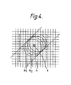
- Figure 4 is a pictorial representation of the effect of several brush stamps in a particular stroke.
- Each small square such as K represents a picture point in the picture being produced are the circles m, m 2 .» represent successive brush stamps, each brush stamp enclosing a group of picture points.
- the shape RAM 18 (which corresponds to 4) holds signals representing the distribution of colour effected by the selected brush to each picture point 'covered' by the brush at any one position of the brush. These signals remain unchanged for as long as any particular implement is selected and in general the signals define the distribution of the brush to a rectangle of picture points such as indicated by the dotted outline a. For picture points in the rectangle which are outside the stamp of the brush, the distribution signals would be zero.
- the distribution signals may vary to represent the brush shape as explained in our U.K. Patent 2089622.
- the position of the brush stamp will change and for each of a succession of positions of the stamps, the signals from the shape RAM 18 are read and are processed as will be explained later.
- successive brush stamps overlap when a stroke is made, and as can be seen in Figure 4 in the case of picture point K, for example the distribution signal for different points in the brush stamps m, m 2 ........ should be used for processing of the same point in the picture.
- the number of brush stamps affecting any one point in the picture, when making a single stroke can be high, as much as ten or more depending on the speed with which the artist makes the stroke.
- the computer 16 When signals are received by the computer 16 from the touch tablet and keyboard, the computer produces the addresses in a patch, and loads the selected colour video signal components into patch RAM 17 and the distribution signals into shape RAM 18. Up to this point the system works in the same manner as the prior art apparatus, but at this point the distribution signals are not immediately used to control the processing of the colour signals from 17 with the stored signals from the frame store. Instead the distribution signals are processed in a manner described later and held in an another store 19 called the area RAM until the appropriate time in the respective cycle of frame store 13, which in this case is a cyclic frame delay store instead of a RAM.
- the size of the store 19 is such that it can store a distribution signal for each picture point which is contained within that portion of a stroke that can be drawn in a frame time. This size can be calculated.
- the computer When the operator draws a line on the touch tablet the computer identifies the co-ordinates of the points along that section of a line drawn in any particular frame period.
- the distribution signals from shape RAM 18 for each picture point enclosed within successive brush stamps along the line are processed to produce a new set of distribution signals for the picture points enclosed within the respective portion of the stroke.
- This processing is carried out under control of the computer 16 and takes into account the pressure factor from the stylus, the pressure multiplier (such as 6 in Figure 1) is omitted for convenience in Figure 2, but would normally be located between 18 and 19. Other factors such as dwell time of the stylus over a particular point can also be taken into account.
- the result in processing of the distribution signals is that at the end of a frame period the signals in area RAM 19 will represent the video effect of each point of the stroke, as if drawn using white paint on a black background.
- the distribution signals are used as control signals to control the signals from the patch RAM 17 and also as applicable, the signals from the frame delay 13. It should be clear that the signals from the area RAM 19 may relate to a succession of brush stamps which would normally overlap each other, as described from a brush stamp which shows only the distribution for one brush position.
- the computer 16 not only produces addresses in successive patches, but produces via address generator 20 and holds the co-ordinates of successive points relative to the frame delay store B within the length of line drawn in one cycle period of the store 13. These co-ordinates are translated into stamp addresses in the area RAM 19, for successive picture points enclosed within brush stamps along the line, assuming that the area represented by the RAM 19 is positioned relative to the image frame to contain the length of stroke along the line drawn on the touch tablet.
- the computer also generates in 20 and holds a reference address, in terms of the frame delay store 13, for the area in area RAM 19, usually the address of the 2 top left hand corner of the area when positioned as aforesaid.
- the stamp addresses are used to read distribution signals for successive brush stamps from the shape RAM 18 and apply them to the area RAM 19, one set of such signals being applied for each brush stamp along a length of line.
- the reference address is compared with the successive addresses accessed during a read/write cycle of the store 11.
- the computer initiates an addressing cycle of an address generator 20 to read the signals from the area RAM 19 to the processor 12, which comprises a subtractor 12A, multiplier 12B and adder 12C arranged as shown.
- This processor is equivalent to processor 5 in Figure 1.
- the addressing cycle of 20 is such that each signal in the area RAM 19 is read in synchronism with the signal read from the corresponding picture point in the store 13, by the read/write cycle generate 22 the area represented by the RAM 19 positioned as aforesaid.
- the signal read from the RAM 19 is the signal K which is used in the processor 12 for the signals A and B as described in relation to Figure 1.
- the access to area RAM 19 is of sufficient speed to enable the new picture point signals to be produced from processor 12 at the correct timing for the refresh cycle.
- any picture point addresses which may be generated by the operator using the stylus during that interval are held in the computer until the processing in the processor 12 is completed for the respective frame (or field) period.
- the whole frame period other than such intervals is however available for processing the distribution signals and writing them in the area RAM 19.
- the address in the store for the corner of the next area stored in area RAM 19 is produced in address generator 20 and at the next cycle time the further set of newly processed distribution signals is used in the processor 12. So the system described here receives signals indicative of a stroke to appear on the image and taking one section of that stroke, processes the brush stamps for this section before adding the new information as the store 13 is cycled.
- each point in a line designated on the touch tablet has - distribution signals for the patch of picture points including ones adjacent to it and the distribution signals for successive points are combined to produce a distribution signal for a section of the stroke to be drawn where:-ahe respective patches of distribution signals (brush stamps) overlap.
- the processing was such that each patch was individually processed so that new video signals were stored in the frame store patch by patch.
- the next patch was processed then for points which overlapped the new video signal included a component produced by multiplying the stored video signal by the distribution signal so this new signal would be related to the two distribution signals.
- the processor for this system produces an output signal for each picture point which is a blend of the colour signal A stored in the frame store for that point and the incoming colour signal B for the same point from a patch RAM.
- the signal which is output from the processor and written into the frame store to replace the signal A is (1-K)A + KB where K is the distribution signal.
- the systems illustrated would include three paths for three video components, for example, Y,I.Q or R,G,B.
- the timing of the system is such that the operator will be able to view the image as it is being created and for this purpose the contents of the store 13 being read to a colour T.V. monitor.
- the signals in store 13 can be committed to a long term store when the operator is satisfied with the picture created.
- the updating of the video signals in the frame delay store 13 is not carried out on reading respective video signals in the area represented by the RAM 17 during the normal read and write cycle.
- the updating is carried out during the field blanking intervals when video signals are not normally read from the store.
- To achieve the updating in the limited time available during blanking intervals it is necessary to have random access to those locations in the store at which video signals are to be found corresponding to the picture points in the area RAM 19.
- the RAM 13 is required to be a random access store; nevertheless, this form of the invention still achieves significant advantages in handling the video signals, since the number of addresses in the frame store 13 which have to be accessed in each cycle is substantially reduced compared with the system illustrated in Figure 1 where the number of addresses to be accessed is the product of the number of brush stamps in a cycle by the number of picture points per patch.
- signals derived by the computer 16 to represent co-ordinates or points on a line drawn by the operator on the touch tablet may in fact be produced by interpolating between signals representing points acutally designated by the touch tablet/stylus combination.
Landscapes
- Engineering & Computer Science (AREA)
- Theoretical Computer Science (AREA)
- Physics & Mathematics (AREA)
- General Physics & Mathematics (AREA)
- General Engineering & Computer Science (AREA)
- Human Computer Interaction (AREA)
- Processing Or Creating Images (AREA)
- Studio Circuits (AREA)
Abstract
Description
- This invention relates to improvements in video image creation systems.
- A prior art system for video image creation is described in our co-pending U.K. Patent 2089625, which is incorporated herein by reference and one example of such a system is shown in Figure 1 hereof. The system is controlled via a touch tablet/stylus combination and a keyboard (not illustrated) and is capable of producing video images that resemble closely those that would be produced using conventional artists materials. To achieve the realism incoming signals and stored signals are mixed so that there is a blending and this blending is controlled by a distribution signal related to the distribution power of the implement which is being simulated. For example, if the operator wishes to draw a stroke on the screen that simulates the use of a wide brush and real paint the operator 'draws' a line on the touch tablet using the stylus and chooses, say, the colour red and the implement 'wide brush'. The
computer 1 receives signals from the touch tablets representing the co-ordinates of points along the line and also command signals for the type of brush and the colour. To achieve the desired effect of a wide stroke in the final image, a patch of picture points adjacent and including each designated picture point must be processed. Taking the co-ordinate signal for the first point on the line the computer produces a corresponding address in the frame store in which signals representing the picture being created are accumulated so that when the signals in thestore 2 are read and applied to a colour TV monitor the first point in the line will appear on the screen of the colour monitor in the position indicated by the stylus on the touch tablet. The address produced by the computer is the address of the corner of the patch of picture point signals to be processed. The computer also causes red video signals to be loaded into a patch of locations in thepatch RAM 3 and the distribution signals for a wide brush to be loaded into a patch of locations in theshape RAM 4. The distribution signal represents the effect produced by a wide brush with white paint on a black background, i.e. the intensity distribution produced by the selected implement. - Starting from the corner address of the patch the computer generates the addresses of all points in the patch referred to the
frame store 2 and for each address generated the signals for that address are read fromframe store 2 andpatch store 3 intoprocessor 5, which comprises twomultipliers adder 10. The processing is done picture point by picture points. The distribution signal for each address is also made available to processor from theshape RAM 4, after being multiplied in 6 by a factor related to the pressure of the stylus on the touch tablet and being perhaps multiplied in 7 by a stencil signal, and it is applied as a multiplication factor K to themultiplier 8. The complement of K, namely 1-K, is produced by thecircuit 11 and applied to themultiplier 9. The output of the processor for each picture point can be seen to be KA + (1-K)B where A is the new signal and B the stored signal and so the value of K determines the proportions of incoming and stored signals which make up the new image signal. The image signals in theframe store 2 are also read and rewritten in thestore 2 cyclically in TV raster format, so that the image being created can be displayed on the TV monitor. - Once each picture point within the patch has been processed the computer generates the address for the corner of the next patch and the processing then runs through this patch. Each patch is called a brush stamp and to produce a continuous line on the screen the brush stamps will have to overlap so signals for some picture points will be processed a plurality of times for one line. The system operates at a speed such that the lines are seen on a monitor at essentially the same time as the operator draws them. It will be understood that this is a simplified explanation of the system and it will in fact operate on three video signal components separately, say for example R, G, B signals.
- This system produces images which are very close to those produced using paint on paper etc. although the images are made up from colour video signals and viewed on a colour T.V. monitor. However, the system requires random access to the frame store, for updating the image in response to eachapplication of the stylus, which access is interleaved with the normal reading of the video signals in TV raster format for display or refresh purposes. In addition to this complication, the use of a random access store as the frame store for the video signals, which is necessary for the processing, is costly.
- The object of the invention is to produce a video image creation system which will produce realistic images in approximately real time more advantageously and preferably also without the use of a random access frame store.
- According to the present invention there is provided a video image creation system comprising operator controlled means for designating points in a line to be produced on an image, means responsive to said operator controlled means for generating a patch of signals representing the video effect of successive overlapping brush stamps along said line, a store for video signals representing the image, means for sequentially reading video signals from said store, and means for updating the signals in said store once per reading cycle thereof in response to video effect signals generated during a preceding cycle period.
- Further according to the present invention there is provided a video image creation system comprising; operator controlled means for designating points on an image to be created, means for generating brush stamp signals for controlling the video effect of signals to be used in the image, means for multiplying factors related to successive brush stamp signals for a point to generate a signal representing the effect of overlapping brush stamps, means for storing colour video signals representing an image, said store means being updated at intervals, and means for updating the signals in said store at intervals in response to the said generated signal.
- One embodiment of the present invention will now be described with reference to the accompanying drawings :
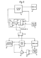
- Figure 1 shows an example of a prior art system.
- Figure 2 shows one example of an embodiment of this invention.
- Figure 3 shows a second example of an embodiment of this invention.
- Figure 4 is a pictorial representation of the operation of the embodiment.
- The invention takes advantage of memory chips that can be assembled to produce a store which is continuously recycled to introduce a one frame delay. In the example of the prior art system described herein the frame store was composed of random access memory chips so that the image signals processing could be carried out as required in response to the operators input.
- As in the prior art system the system in Figure 2 receives signals from the touch table/stylus combination giving co-ordinates of points on the touch tablet along a line drawn by the operator. The brush shape, size, the paint colour etc. are also available to be chosen by the operator in the same manner as in the prior art system.
- Figure 4 is a pictorial representation of the effect of several brush stamps in a particular stroke. Each small square such as K represents a picture point in the picture being produced are the circles m, m2 ....... represent successive brush stamps, each brush stamp enclosing a group of picture points. The shape RAM 18 (which corresponds to 4) holds signals representing the distribution of colour effected by the selected brush to each picture point 'covered' by the brush at any one position of the brush. These signals remain unchanged for as long as any particular implement is selected and in general the signals define the distribution of the brush to a rectangle of picture points such as indicated by the dotted outline a. For picture points in the rectangle which are outside the stamp of the brush, the distribution signals would be zero. Within the stamp, the distribution signals may vary to represent the brush shape as explained in our U.K. Patent 2089622. As the artist moves the stylus, the position of the brush stamp will change and for each of a succession of positions of the stamps, the signals from the
shape RAM 18 are read and are processed as will be explained later. In general successive brush stamps overlap when a stroke is made, and as can be seen in Figure 4 in the case of picture point K, for example the distribution signal for different points in the brush stamps m, m2 ........ should be used for processing of the same point in the picture. In practice, the number of brush stamps affecting any one point in the picture, when making a single stroke, can be high, as much as ten or more depending on the speed with which the artist makes the stroke. - When signals are received by the
computer 16 from the touch tablet and keyboard, the computer produces the addresses in a patch, and loads the selected colour video signal components intopatch RAM 17 and the distribution signals intoshape RAM 18. Up to this point the system works in the same manner as the prior art apparatus, but at this point the distribution signals are not immediately used to control the processing of the colour signals from 17 with the stored signals from the frame store. Instead the distribution signals are processed in a manner described later and held in an anotherstore 19 called the area RAM until the appropriate time in the respective cycle offrame store 13, which in this case is a cyclic frame delay store instead of a RAM. The size of thestore 19 is such that it can store a distribution signal for each picture point which is contained within that portion of a stroke that can be drawn in a frame time. This size can be calculated. When the operator draws a line on the touch tablet the computer identifies the co-ordinates of the points along that section of a line drawn in any particular frame period. The distribution signals fromshape RAM 18 for each picture point enclosed within successive brush stamps along the line are processed to produce a new set of distribution signals for the picture points enclosed within the respective portion of the stroke. This processing is carried out under control of thecomputer 16 and takes into account the pressure factor from the stylus, the pressure multiplier (such as 6 in Figure 1) is omitted for convenience in Figure 2, but would normally be located between 18 and 19. Other factors such as dwell time of the stylus over a particular point can also be taken into account. The result in processing of the distribution signals is that at the end of a frame period the signals inarea RAM 19 will represent the video effect of each point of the stroke, as if drawn using white paint on a black background. The distribution signals are used as control signals to control the signals from thepatch RAM 17 and also as applicable, the signals from theframe delay 13. It should be clear that the signals from thearea RAM 19 may relate to a succession of brush stamps which would normally overlap each other, as described from a brush stamp which shows only the distribution for one brush position. - The
computer 16 not only produces addresses in successive patches, but produces viaaddress generator 20 and holds the co-ordinates of successive points relative to the frame delay store B within the length of line drawn in one cycle period of thestore 13. These co-ordinates are translated into stamp addresses in thearea RAM 19, for successive picture points enclosed within brush stamps along the line, assuming that the area represented by theRAM 19 is positioned relative to the image frame to contain the length of stroke along the line drawn on the touch tablet. The computer also generates in 20 and holds a reference address, in terms of theframe delay store 13, for the area inarea RAM 19, usually the address of the 2 top left hand corner of the area when positioned as aforesaid. The stamp addresses are used to read distribution signals for successive brush stamps from theshape RAM 18 and apply them to thearea RAM 19, one set of such signals being applied for each brush stamp along a length of line. - The reference address is compared with the successive addresses accessed during a read/write cycle of the
store 11. When identity is detected, the computer initiates an addressing cycle of anaddress generator 20 to read the signals from thearea RAM 19 to theprocessor 12, which comprises a subtractor 12A, multiplier 12B and adder 12C arranged as shown. This processor is equivalent toprocessor 5 in Figure 1. The addressing cycle of 20 is such that each signal in thearea RAM 19 is read in synchronism with the signal read from the corresponding picture point in thestore 13, by the read/write cycle generate 22 the area represented by theRAM 19 positioned as aforesaid. The signal read from theRAM 19 is the signal K which is used in theprocessor 12 for the signals A and B as described in relation to Figure 1. - It will be understood that the procedure described is repeated for every stroke, or length of stroke, drawn within successive cycle periods of the
frame delay store 13. It will be appreciated that for any picture point signal read from thestore 13, at a time when K is zero, the signal will be rewritten in thestore 13 without change, i.e. it is merely refreshed. An existing signal B is modified only if the operator has made a new stroke over the respective picture point. Nevertheless the updating is performed during the normal read/write cycles of thestore 13. Thepatch store 17 for the selected colour in the case of Figure 2 has to provide the appropriate signals for all picture points in the area represented by theRAM 17. A register, from which the same colour signals can be read repeatedly in time with the addressing, effected by theadder generator 20 could be used instead of the RAM. The access toarea RAM 19 is of sufficient speed to enable the new picture point signals to be produced fromprocessor 12 at the correct timing for the refresh cycle. When a set of processed distribution signals from thearea RAM 19 is being used in theprocessor 12, any picture point addresses which may be generated by the operator using the stylus during that interval are held in the computer until the processing in theprocessor 12 is completed for the respective frame (or field) period. The whole frame period other than such intervals is however available for processing the distribution signals and writing them in thearea RAM 19. Starting from any such interval, the address in the store for the corner of the next area stored inarea RAM 19 is produced inaddress generator 20 and at the next cycle time the further set of newly processed distribution signals is used in theprocessor 12. So the system described here receives signals indicative of a stroke to appear on the image and taking one section of that stroke, processes the brush stamps for this section before adding the new information as thestore 13 is cycled. - In the system shown in Figure 2 the processing selected for the distribution signals is relatively simple. Each point in a line designated on the touch tablet has - distribution signals for the patch of picture points including ones adjacent to it and the distribution signals for successive points are combined to produce a distribution signal for a section of the stroke to be drawn where:-ahe respective patches of distribution signals (brush stamps) overlap. In the prior art system the processing was such that each patch was individually processed so that new video signals were stored in the frame store patch by patch. When the next patch was processed then for points which overlapped the new video signal included a component produced by multiplying the stored video signal by the distribution signal so this new signal would be related to the two distribution signals. In the system illustrated in Figure 2, it has been found to be sufficient to process the distribution signals accumulated in the
store 19 simply by adding the distribution signals for overlapping picture points in successive brush stamps, such addition being achieved under the control of thecomputer 16. The system is scaled so that the maximum video effect signal, which results for the addition of the distribution signals for the maximum number of picture points which may overlap, is normalised to unity. In a simple case this may be done by dividing the sum by the maximum number of picture points. If desired the video effect signals accumulated in thestore 19 can be non linearly modified, for example with the aid of a look up table, so that the signal is 'compressed' as a function of its magnitude before normalisation to unity. This will produce an effect of processing closer to that produced by the prior art processing system. - A second way of processing the distribution signals to produce the video effect signals is shown in Figure 3.
- To understand this processing it is necessary to consider the processing of the picture point signals which occurs in the system of UK Patent 2089625. The processor for this system produces an output signal for each picture point which is a blend of the colour signal A stored in the frame store for that point and the incoming colour signal B for the same point from a patch RAM. The signal which is output from the processor and written into the frame store to replace the signal A is (1-K)A + KB where K is the distribution signal.
- If we consider a picture point in a first brush stamp then the output Al = (1 - Ko) Ao + Ko Bo, where the suffixes 0 refer brush stamp to the first and the
suffix 1 refers to the resultant signals stored in the frame store. When the next brush stamp overlaps this point with a value Kl then:


- It will be obvious that for the nth overlapping brush stamp at the point under consideration:
An+1 = (K'n ....K'o)Ao + (1 - K'n ....K'o)Bo So if the combined brush stamp signals are processed by the computer to produce (K'n....K'o) then by using (1 - (K'n ....K'o)) in theprocessor 12 as in Figure 2 the same result as in UK patent application number 8136539 can be achieved. This processing can be achieved using fairly simple circuits such as the components 24-26, shown in Figure 3. When the brush stamp signals have been loaded intoshape RAM 18 the first value for K for a picture point is input tosubtractor 26 which produces Ko' = 1-Ko and this is stored inarea RAM 19. When the next value for K for that point is accessed for an overlapping brush stamp this is converted to R1 and forms one input tomultiplier 25, the second input being Ko' fromarea RAM 19. The resultant Kl Ko' is then written intoRAM 19. When all the brush stamps for that section of the stroke drawn in the frame period have been processed each point in the stroke will have a value for Kn'....Ko' stored inarea RAM 19. In this case before being applied toprocessor 12 the values for each point fromarea RAM 19 are passed throughsubtractor 24 to produced K = (1 - Kn' ....Ko') - In practice the systems illustrated would include three paths for three video components, for example, Y,I.Q or R,G,B. The timing of the system is such that the operator will be able to view the image as it is being created and for this purpose the contents of the
store 13 being read to a colour T.V. monitor. The signals instore 13 can be committed to a long term store when the operator is satisfied with the picture created. - In an alternative form of the invention, the updating of the video signals in the
frame delay store 13 is not carried out on reading respective video signals in the area represented by theRAM 17 during the normal read and write cycle. The updating is carried out during the field blanking intervals when video signals are not normally read from the store. To achieve the updating in the limited time available during blanking intervals it is necessary to have random access to those locations in the store at which video signals are to be found corresponding to the picture points in thearea RAM 19. Therefore in this case, theRAM 13 is required to be a random access store; nevertheless, this form of the invention still achieves significant advantages in handling the video signals, since the number of addresses in theframe store 13 which have to be accessed in each cycle is substantially reduced compared with the system illustrated in Figure 1 where the number of addresses to be accessed is the product of the number of brush stamps in a cycle by the number of picture points per patch. - It will be appreciated that some of the signals derived by the
computer 16 to represent co-ordinates or points on a line drawn by the operator on the touch tablet, may in fact be produced by interpolating between signals representing points acutally designated by the touch tablet/stylus combination.
Claims (11)
and means (23) for displaying said signals from said store,
characterised by, means (19) for generating a patch of signals representing the video effect of successive overlapping brush stamps along said line,
means (22) for reading video signals from said store, and said processing means operating to update the signals in said store once per reading cycle thereof in response to video effect signals generated during a preceding cycle period.
characterised by, means for combining the distribution signals for individual image points to produce video effect signals for the respective points,
and means for updating the video signal in said store for particular image points in response to the stored video signal for the point, said colour signal and the respective video effect signal.
Applications Claiming Priority (4)
| Application Number | Priority Date | Filing Date | Title |
|---|---|---|---|
| GB8510137 | 1985-04-20 | ||
| GB858510137A GB8510137D0 (en) | 1985-04-20 | 1985-04-20 | Video image creation systems |
| GB8520053 | 1985-08-09 | ||
| GB858520053A GB8520053D0 (en) | 1985-08-09 | 1985-08-09 | Video image creation systems |
Publications (2)
| Publication Number | Publication Date |
|---|---|
| EP0202747A2 true EP0202747A2 (en) | 1986-11-26 |
| EP0202747A3 EP0202747A3 (en) | 1989-10-18 |
Family
ID=26289149
Family Applications (1)
| Application Number | Title | Priority Date | Filing Date |
|---|---|---|---|
| EP86302545A Withdrawn EP0202747A3 (en) | 1985-04-20 | 1986-04-07 | Improvements in or relating to video image creation systems |
Country Status (2)
| Country | Link |
|---|---|
| EP (1) | EP0202747A3 (en) |
| JP (1) | JP2552113B2 (en) |
Cited By (10)
| Publication number | Priority date | Publication date | Assignee | Title |
|---|---|---|---|---|
| GB2191919B (en) * | 1986-06-19 | 1990-05-23 | British Broadcasting Corp | Computer graphics |
| WO1991011774A1 (en) * | 1990-02-05 | 1991-08-08 | Spaceward Holdings Limited | Video image creation system |
| WO1991015830A1 (en) * | 1990-03-30 | 1991-10-17 | Spaceward Holdings Limited | Video image creation |
| WO1991019266A1 (en) * | 1990-06-08 | 1991-12-12 | Accom, Incorporated | Computer graphics |
| EP0439333A3 (en) * | 1990-01-23 | 1993-01-20 | Crosfield Electronics Limited | Electronic image modification |
| EP0525953A1 (en) * | 1991-07-01 | 1993-02-03 | Crosfield Electronics Limited | Electronic image generation apparatus |
| GB2260673A (en) * | 1991-10-18 | 1993-04-21 | Quantel Ltd | Improvements in or relating to electronic graphic systems |
| EP0497598A3 (en) * | 1991-01-31 | 1994-04-20 | Quantel Ltd | |
| US5357265A (en) * | 1989-04-17 | 1994-10-18 | Quantel Limited | Electronic graphic system |
| US5412402A (en) * | 1989-09-01 | 1995-05-02 | Quantel Limited | Electronic graphic systems |
Families Citing this family (1)
| Publication number | Priority date | Publication date | Assignee | Title |
|---|---|---|---|---|
| JPH08101922A (en) * | 1991-01-07 | 1996-04-16 | Shima Seiki Mfg Ltd | Image editing / creating apparatus and image editing / creating method |
Family Cites Families (3)
| Publication number | Priority date | Publication date | Assignee | Title |
|---|---|---|---|---|
| GB2140257B (en) * | 1980-12-04 | 1985-09-18 | Quantel Ltd | Video image creation |
| US4514818A (en) * | 1980-12-04 | 1985-04-30 | Quantel Limited | Video image creation system which simulates drafting tool |
| GB2116407B (en) * | 1982-03-11 | 1986-04-23 | Quantel Ltd | Electonically synthesised video palette |
-
1986
- 1986-04-07 EP EP86302545A patent/EP0202747A3/en not_active Withdrawn
- 1986-04-16 JP JP61086209A patent/JP2552113B2/en not_active Expired - Lifetime
Cited By (13)
| Publication number | Priority date | Publication date | Assignee | Title |
|---|---|---|---|---|
| GB2191919B (en) * | 1986-06-19 | 1990-05-23 | British Broadcasting Corp | Computer graphics |
| US5357265A (en) * | 1989-04-17 | 1994-10-18 | Quantel Limited | Electronic graphic system |
| US5412402A (en) * | 1989-09-01 | 1995-05-02 | Quantel Limited | Electronic graphic systems |
| EP0439333A3 (en) * | 1990-01-23 | 1993-01-20 | Crosfield Electronics Limited | Electronic image modification |
| WO1991011774A1 (en) * | 1990-02-05 | 1991-08-08 | Spaceward Holdings Limited | Video image creation system |
| WO1991015830A1 (en) * | 1990-03-30 | 1991-10-17 | Spaceward Holdings Limited | Video image creation |
| WO1991019266A1 (en) * | 1990-06-08 | 1991-12-12 | Accom, Incorporated | Computer graphics |
| EP0497598A3 (en) * | 1991-01-31 | 1994-04-20 | Quantel Ltd | |
| US5335318A (en) * | 1991-07-01 | 1994-08-02 | Crosfield Electronics Limited | Electronic image generation apparatus including a camera for recording a region and producing a control data array |
| EP0525953A1 (en) * | 1991-07-01 | 1993-02-03 | Crosfield Electronics Limited | Electronic image generation apparatus |
| GB2260673A (en) * | 1991-10-18 | 1993-04-21 | Quantel Ltd | Improvements in or relating to electronic graphic systems |
| GB2260673B (en) * | 1991-10-18 | 1995-10-11 | Quantel Ltd | Improvements in or relating to electronic graphic systems |
| US5557713A (en) * | 1991-10-18 | 1996-09-17 | Quantel Limited | Improvements in or relating to electronic graphic systems |
Also Published As
| Publication number | Publication date |
|---|---|
| JPS6235980A (en) | 1987-02-16 |
| EP0202747A3 (en) | 1989-10-18 |
| JP2552113B2 (en) | 1996-11-06 |
Similar Documents
| Publication | Publication Date | Title |
|---|---|---|
| US4524421A (en) | Computerized graphics system and method using an electronically synthesized palette | |
| US5276787A (en) | Electronic graphic system | |
| EP0710377B1 (en) | A data display apparatus and method for displaying digital samples of signal data on a bit mapped display system | |
| US5175625A (en) | Video image creation systems combining overlapping stamps in a frame period before modifying the image | |
| US4954970A (en) | Video overlay image processing apparatus | |
| US4532605A (en) | True zoom of a displayed image | |
| US4992780A (en) | Method and apparatus for storing a two-dimensional image representing a three-dimensional scene | |
| US5276788A (en) | Video image creation systems | |
| US4225861A (en) | Method and means for texture display in raster scanned color graphic | |
| JP2773354B2 (en) | Special effect device and special effect generation method | |
| US4631691A (en) | Video display device simulation apparatus and method | |
| EP0202747A2 (en) | Improvements in or relating to video image creation systems | |
| US4706074A (en) | Cursor circuit for a dual port memory | |
| JPS6191777A (en) | Video image forming apparatus | |
| GB2140257A (en) | Video image creation | |
| KR970012084A (en) | Graph display apparatus and method | |
| US5977999A (en) | Electronic graphic apparatus with low data transfer rate between data stores | |
| US5164716A (en) | Image processing system | |
| GB2137856A (en) | Image processing system | |
| GB2238214A (en) | Electronic graphic system combines images using variable density stencil | |
| JP2906643B2 (en) | Document processing device | |
| GB2317309A (en) | An electronic graphic system | |
| JPS5866991A (en) | Cursor display control system | |
| JPS6180292A (en) | Display cotnrol system | |
| JPS62204297A (en) | image display device |
Legal Events
| Date | Code | Title | Description |
|---|---|---|---|
| PUAI | Public reference made under article 153(3) epc to a published international application that has entered the european phase |
Free format text: ORIGINAL CODE: 0009012 |
|
| AK | Designated contracting states |
Kind code of ref document: A2 Designated state(s): DE FR GB |
|
| PUAL | Search report despatched |
Free format text: ORIGINAL CODE: 0009013 |
|
| AK | Designated contracting states |
Kind code of ref document: A3 Designated state(s): DE FR GB |
|
| 17P | Request for examination filed |
Effective date: 19900411 |
|
| 17Q | First examination report despatched |
Effective date: 19920311 |
|
| STAA | Information on the status of an ep patent application or granted ep patent |
Free format text: STATUS: THE APPLICATION IS DEEMED TO BE WITHDRAWN |
|
| 18D | Application deemed to be withdrawn |
Effective date: 19920922 |
|
| RIN1 | Information on inventor provided before grant (corrected) |
Inventor name: MILES, BARRY DONALD RUBERRY |