EP0202745A2 - Method for moveout correction and stacking velocity estimation of offset vertical seismic profile data - Google Patents
Method for moveout correction and stacking velocity estimation of offset vertical seismic profile data Download PDFInfo
- Publication number
- EP0202745A2 EP0202745A2 EP86302489A EP86302489A EP0202745A2 EP 0202745 A2 EP0202745 A2 EP 0202745A2 EP 86302489 A EP86302489 A EP 86302489A EP 86302489 A EP86302489 A EP 86302489A EP 0202745 A2 EP0202745 A2 EP 0202745A2
- Authority
- EP
- European Patent Office
- Prior art keywords
- offset
- vsp
- formula
- rms
- data
- Prior art date
- Legal status (The legal status is an assumption and is not a legal conclusion. Google has not performed a legal analysis and makes no representation as to the accuracy of the status listed.)
- Granted
Links
- 238000000034 method Methods 0.000 title claims abstract description 32
- 238000012937 correction Methods 0.000 title claims abstract description 30
- 230000015572 biosynthetic process Effects 0.000 abstract 1
- 238000012545 processing Methods 0.000 description 12
- 238000004458 analytical method Methods 0.000 description 8
- 238000005192 partition Methods 0.000 description 5
- 238000001228 spectrum Methods 0.000 description 5
- 238000004422 calculation algorithm Methods 0.000 description 3
- 230000003044 adaptive effect Effects 0.000 description 2
- 238000011161 development Methods 0.000 description 2
- 230000018109 developmental process Effects 0.000 description 2
- 238000007689 inspection Methods 0.000 description 2
- 230000000717 retained effect Effects 0.000 description 2
- 238000006467 substitution reaction Methods 0.000 description 2
- NAWXUBYGYWOOIX-SFHVURJKSA-N (2s)-2-[[4-[2-(2,4-diaminoquinazolin-6-yl)ethyl]benzoyl]amino]-4-methylidenepentanedioic acid Chemical compound C1=CC2=NC(N)=NC(N)=C2C=C1CCC1=CC=C(C(=O)N[C@@H](CC(=C)C(O)=O)C(O)=O)C=C1 NAWXUBYGYWOOIX-SFHVURJKSA-N 0.000 description 1
- 238000013459 approach Methods 0.000 description 1
- 230000005540 biological transmission Effects 0.000 description 1
- 238000004364 calculation method Methods 0.000 description 1
- 238000007796 conventional method Methods 0.000 description 1
- 238000000354 decomposition reaction Methods 0.000 description 1
- 238000009795 derivation Methods 0.000 description 1
- 238000005553 drilling Methods 0.000 description 1
- 238000011156 evaluation Methods 0.000 description 1
- 238000002474 experimental method Methods 0.000 description 1
- 238000003384 imaging method Methods 0.000 description 1
- 238000012886 linear function Methods 0.000 description 1
- 238000007781 pre-processing Methods 0.000 description 1
- 238000003672 processing method Methods 0.000 description 1
- 238000005070 sampling Methods 0.000 description 1
- 230000003068 static effect Effects 0.000 description 1
- 230000001629 suppression Effects 0.000 description 1
- 238000003325 tomography Methods 0.000 description 1
- 230000009466 transformation Effects 0.000 description 1
- 230000000007 visual effect Effects 0.000 description 1
Images


Classifications
-
- G—PHYSICS
- G01—MEASURING; TESTING
- G01V—GEOPHYSICS; GRAVITATIONAL MEASUREMENTS; DETECTING MASSES OR OBJECTS; TAGS
- G01V1/00—Seismology; Seismic or acoustic prospecting or detecting
- G01V1/28—Processing seismic data, e.g. for interpretation or for event detection
- G01V1/36—Effecting static or dynamic corrections on records, e.g. correcting spread; Correlating seismic signals; Eliminating effects of unwanted energy
- G01V1/362—Effecting static or dynamic corrections; Stacking
-
- G—PHYSICS
- G01—MEASURING; TESTING
- G01V—GEOPHYSICS; GRAVITATIONAL MEASUREMENTS; DETECTING MASSES OR OBJECTS; TAGS
- G01V2210/00—Details of seismic processing or analysis
- G01V2210/10—Aspects of acoustic signal generation or detection
- G01V2210/16—Survey configurations
- G01V2210/161—Vertical seismic profiling [VSP]
-
- G—PHYSICS
- G01—MEASURING; TESTING
- G01V—GEOPHYSICS; GRAVITATIONAL MEASUREMENTS; DETECTING MASSES OR OBJECTS; TAGS
- G01V2210/00—Details of seismic processing or analysis
- G01V2210/50—Corrections or adjustments related to wave propagation
- G01V2210/52—Move-out correction
-
- G—PHYSICS
- G01—MEASURING; TESTING
- G01V—GEOPHYSICS; GRAVITATIONAL MEASUREMENTS; DETECTING MASSES OR OBJECTS; TAGS
- G01V2210/00—Details of seismic processing or analysis
- G01V2210/50—Corrections or adjustments related to wave propagation
- G01V2210/52—Move-out correction
- G01V2210/522—Dip move-out [DMO]
Definitions
- This invention relates to a method for moveout correction and stacking velocity estimation of offset vertical seismic profile data.
- VSP Vertical Seismic Profiles
- source-induced noise such as casing ring and tube waves can obscure reflection events when the source is close to the well
- the configuration of the drilling support equipment on a well pad may necessitate placement of a source at some distance from the well and local land conditions may dictate the source placement.
- the most frequent demand for long offset VSP data acquisition is the requirement for tube wave suppression.
- the amplitude of tube waves diminishes with increasing source offset from a well.
- the time delay of seismic reflection events resulting from a long offset source is usually less than the delay of tube wave inception. This tends to keep reflection events well separated from tube waves, resulting in much better VSP data quality.
- Borehole seismic acquisition programs can be designed to obtain data at multiple long offsets for a number of reasons.
- Applications include the provision of offset seismic profiles recorded in a well that are directly correlative to well log data, the acquisition of seismic data free of surface organized noise, the determination of seismic transmission and reflection properties with offset and depth, acquisition of data appropriate for tomography/inversion and imaging, the delineation of reservoir properties when offset VSP profiles are conducted in a field for several wells with 2-D or 3-D applications and determination of depth and inter-reflector velocities of reflectors below the borehole Total Depth (TD) from lookahead VSP data.
- TD Total Depth
- offset VSP offset VSP
- lateral seismic profile offset seismic profile
- offset seismic profile in a well are used as equivalent terms, meaning either seismic data acquisition for a multiplicity of. receivers in a well recording data from each of a multiplicity of sources on the surface; or the reciprocal situation for which a multiplicity of receivers on the surface record data from each of a multiplicity of source locations in the well.
- Offset VSP processing has not been as extensively developed as surface seismic data processing or conventional VSP processing.
- Conventional VSP data processing assumes that the source offset from the well is essentially zero.
- CDP Common Depth Point
- This concept utilizes the near-hyperbolicity of primary seismic reflection arrivals to align redundant reflections obtained from multiple shot/receiver experiments conducted on the earth's surface.
- Some geopnysical contractors approach the problem of aligning reflections from offset VSP data through ray tracing.
- Surface seismic data may be moveout corrected by ray tracing, but it is far more common to employ a hyperbolic moveout correction formula and develop velocity spectra in the applications.
- FIGURE 1 is a plan view of a system for obtaining vertical seismic profile data
- acoustic pulse sources 14, 16, 18, 20 and 22 are located on the earth's surface 12 at different distances x from a borehole 24 in which an acoustic pulse receiver 26 is suspended.
- a travel path 28 is illustrated as the path of an acoustic pulse from acoustic source 18 to a reflector 30.
- Ray path 32 is the path of an acoustic pulse from source 18 that has been reflected off reflector 30 and received by receiver 26.
- Ray path 34 is the path of an acoustic pulse generated by source 18 and traveling directly to receiver 26, normally called the "first break" path.
- the seismic source and receiver are regarded to be nearly on the same vertical line.
- Primary seismic reflections obtained from a receiver located at various depths may be aligned or flattened by adding the one-way first break time TB(zR) to tne seismic record obtained with the receiver at depth z R .
- VSP data are preprocessed to remove downgoing waves before reflection alignment is achieved.
- the primary reflection travel time T is given by where x is the offset distance of the source from the borehole, z R is the depth of the receiver in the borehole, and v O is the constant velocity describing the media.
- the first break times T B (z R ) for normal incidence are already computed from VSP data in a separate algorithm which may be any currently in use in the art. Such an algorithm attempts to correct for the slant path of the direct arrival rays wherr the source is offset some distance x. If the velocity v 0 appearing in formula (5) is interpreted as the stacking velocity, formula (5) may be rewritten as
- v(t ⁇ ) stack appearing in formula (7), is difficult to interpret because of the asymmetry of ray paths.
- An offset VSP moveout formula is disclosed by the present invention in which the velocities are completely interpretable. This formula applies to laterally homogeneous media.
- Formula (1) may be interpreted in several different ways. If one assumes that
- FIGURE 2 a more detailed illustration of FIGURE 1 is presented. If the point at which an acoustic pulse traveling down path 28 meets with reflector 30 is labeled as X R , the point on reflector 30 which is the shortest distance from source 18 is labeled as P. The point on reflector 30 which intersects borehole 24 is labeled as z O . The point at which receiver 26 is located in borehole 24 is labeled as z R . A continuation of travel path 32 to surface 12 is indicated in travel time of ⁇ T. The space from borehole 24 along surface 12 which a continuation of ray path 32 would intersect surface 12 is labeled as ⁇ x. The distance from the intersection of a continuation of ray path 32 and surface 12 to source 18 is labeled as X.
- Equation (14) may be solved for x R , the reflection point, in terms of the source 18 offset x, reflector 30 has a depth z o , and the receiver depth z R ; this results in the expression
- x R is the reflection point and AT is the incremental time for the VSP ray, received at z R , to arrive at the surface a distance ⁇ x from the well. From FIGURE 2, it is s also apparent that
- the offset VSP travel time T is obtained from the surface-to-surface travel time T ss by subtracting the incremental travel time ⁇ T from T ss ; that is where aT is the one-way travel time from the point (O,z R ) to the surface point ( ⁇ x,O).
- the times T B (x,z R ) may be difficult to obtain at long offsets because head refractions may precede these events.
- This formula can be used to obtain velocity spectra in a way that allows the stacking velocities to be interpretable.
- the velocities appearing in formula (26) are the familiar RMS velocities that are estimated by means of stacking velocities in surface seismic data processing.
- the asymmetry in offset VSP source-receiver placement is manifest in the requirement that v RMS (t ⁇ ) and v RMS (T B ) must both appear in the offset VSP moveout correction formula.
- FIGURE 3 depicts a model of five flat reflectors separating layers with the indicated interval velocities.
- the Sierra, VSP ray trace program was used to generate offset VSP data based on this model.
- Geophones were located in the borehole from depths of 50 feet to 3750 feet in increments of 50 feet and a source was placed on the surface from 100 feet offset to the well to 5000 feet offset to the well in increments of 100 feet.
- Tables 1 and 2 of Appendix 2 compare the ray trace times T(x,z R ) delivered by Sierra with those computed with formula (26) for reflectors R S and R 3 , shown in FIGURE 3, for the indicated source offsets x and geophone depths z Ro Inspection of these tables indicates sufficient accuracy of the offset VSP moveout correction formula (26) for use toward the required dynamic corrections for offset VSP data traces.
- Table 3 of Appendix 2 is a compilation of z R , T B (z R ) and v RMS [T B (z R )] together with the two-way, normal incidence travel times for the reflectors R 1 through R 5 and RMS velocity at these reflector horizons for the model depicted in FIGURE 3.
- Table 3 contains the required information to compute the offset VSP travel times listed in Tables 1 and 2 using formula (26).
- the computation of the RMS velocities v RMS (t) was based on the internal velocities and depths depicted in FIGURE 3 with an application of the standard definition
- v(t) is the interval velocity and t may be either one-way or two-way normal incidence travel time.
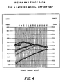
- FIGURE 4 shows the results of ray tracing with the Sierra offset VSP algorithm applied to the five reflector model of FIGURE 3 with the source offset 3,000 feet. Except for the first break events on each trace, the only other events in the seismogram are upcoming arrivals of the primary reflections from the five interfaces in the model. It is usual practice to mute the first breaks on all traces in processing YSP reflection data and appropriate mutes were applied to the data in FIGURE 4 as a conventional preprocessing step. In order to demonstrate the application of formula (26), the reflections from reflector R 1 and R 2 were removed from the seismogram in FIGURE 4 because they were very shallow and the critical offset for reflector R 1 is only about 626 feet. The remaining three reflectors were processed by the conventional VSP processing in which a static time shift equal to T B (z R ) is applied to each trace.
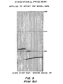
- FIGURE 5 shows the result of applying conventional VSP processing to these data and that a residual correction must be applied to these data to bring reflection events into alignment.
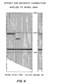
- FIGURE 6 the same data have been dynamically corrected using the offset VSP moveout correction formula (26).
- the actual values of v RMS (t ⁇ ) and vRMS (T B ) were supplied in formula (26), as listed in Table 3.
- Inspection of FIGURE 6 shows adequate reflection alignment for stacking.
- the corresponding stacking traces are also shown in FIGURE 6.
- the demonstration of FIGURE 6 serves as an indication that dynamic offset VSP moveout correction as prescribed in formula (26) can be successfully applied to offset VSP data traces to align primary reflection events without recourse to ray tracing.
- the offset VSP data traces are defined to be D(x,z R ,t) and a seismic trace exists at each offset x and depth of geophone z R .
- This trace is to be transformed into a trace D MO (x,z R ,t ⁇ ), which will be moveout corrected via formula (27).
- the time transformation of formula (26) can be represented as a function H [ ] given by
- the VSP data trace will be sampled in time at a rate at, which will be 1, 2, or 4 milliseconds or some other specified increment.
- the moveout corrected trace D MO is to be sampled at the same rate as the input trace. If then for some value t (i)
- T i is in the interval t j ⁇ T i ⁇ t j+1 , then the moveout corrected trace can be represented by simple linear interpolation as:
- the times T B , T OG and T O are all normal incidence one-way times.
- V RMS (T OG ) can be resolved by the well-known rules for decomposition of root mean square velocity V RMS' that is
- formula (37) is similar to formula (26).
- the VSP moveout prediction given by formula (26) is slightly better than the corresponding prediction given by formula (37) when the geophone is relatively near the reflector, while formula (37) performs slightly better than formula (26) when the geophone is relatively far from the reflector. More often than not, when the geophone is in a shallow position in the well, reflection data of marginal quality are recorded in VSP's for deep reflector locations, and better reflection data are recorded when the geophone is near the reflector. For these reasons, formula (26) is preferred to formula (37) in most applications.
- RMS velocities v RMS (t ⁇ ) for the range 0 ⁇ t ⁇ ⁇ t B (z Rk ), where z R k is the deepest geophone location in a well for which a first break time has been obtained are provided.
- v RMS (t ⁇ ) There will generally be reflection events at times greater than this value of t and the required values of v RMS (t ⁇ ) may be generated by either interpolating the function v RMS (t ⁇ ) for t ⁇ > tg, or by introducing velocities from an external source such as analysis of CDP surface seismic data in the vicinity of the well.
- offset VSP moveout corrections are performed with a fixed RMS velocity function, there is a good probability that reflection alignment will not be optimal.
- imperfect reflection alignment can be troublesome.
- poor reflection alignment is unacceptable because such data will be gathered with the intention of extending reflection horizons away from the well. This leads to the requirement of developing a data adaptive method of obtaining velocities v S (t ⁇ ) to replace the RMS velocities appearing in formula (26) in order to align reflectors in an optimal manner.
- the velocity v S (t ⁇ ) will be a linear function on each interval [t ⁇ (j-1), t ⁇ (j)] and the partition itself may be dictated by knowledge of the function v RMS (t ⁇ ) obtained from first break times or external data.
- the velocities v S (t ⁇ (j)) at the nodes are going to be determined in a data adaptive process.
- the velocity v s (0) can be prescribed by knowledge of near surface conditions. We assume that v S (t) is a continuous function.
- v S (1,n)n 1,2,...,N in a neighborhood of v RMS (t ⁇ (1)) and perform the required evaluation of v S (t B ) for 0 ⁇ t B ⁇ t ⁇ (1).
- VSP moveout correct the traces and display them, one display for each v S (1,n); this will require only several traces at geophone depths near the shallowest portion of the survey. Mute all traces below t ⁇ (1). Qualitatively choose the "best fit" v * S (1) from the suite of velocities v S (1,n).
- VSP moveout correction will be applied for all traces between 0 ⁇ t s ⁇ t ⁇ (j) and the alignment of shallower reflections will be unaltered because velocities v * S (q), q * 1,2,...,j-1 remain fixed.
- the offset VSP CV stack described in Method II above can be applied to data traces for each fixed source offset x. If the depth sampling z R k is coarse and/or there is particular difficulty with establishing lateral continuity of reflector horizons away from the well, Method II may be applied by displaying CV moveout corrected VSP traces in a window of offsets together with a notation indicating the depth of geophones employed. This will allow visual alignment of reflectors from several offsets at once. The window of offsets can be moved maintaining some degree of overlap. It is plausible to moveout correct offset VSP data by fixing the geophone depth and aligning reflectors for all offsets.
- Method II The main features of Method II are retained, but, in each interval [t ⁇ (j-1), t ⁇ (j)].
- a semblance or coherency measure is employed similar to VIP processing. Instead of a suite of displays of moveout corrected traces for each of a set of sweep velocities, a graph of semblance as a function of t ⁇ is output. This method has the disadvantage of being very time-consuming, just as with VIP processing, however, it does attempt to automate stacking velocity analysis.
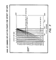
- Equation (15) the relationship among the variables reflection point x R' geophone depth z R , reflector depth z 0 , and source offset from the well x is expressed for flat layers. It is clear from this formula that for a fixed reflector depth and source offset, the subsurface reflection point x R varies significantly as the geophone depth is varied. In order to illustrate this variability, consider FIGURE 7 which is intended to summarize equation (15). A source is placed 2,000' from the well and the geophone depth is varied in the range indicated on the vertical axis. Curves of constant reflector depth are displayed in FIGURE 7. The coordinate of the reflection point x R is the offset distance indicated vertically below the intersection of geophone depth with the reflector curve. Equation (15) refers to a constant velocity medium.
- Reflections issuing from approximately the same subsurface location is a concept similar to CDP gather and is demonstrated by the present invention.
- the interval between the well (at offset 0') and the midpoint between the welt and the source (at offset 1,000') is partitioned into six equal intervals called bins.
- the number of bins N it is required to chose the number of bins N. If the bins are too coarse, reflections will be stacked over a wide portion of a reflector and will be smeared, whereas, if the bins are too fine, stacking will be nearly at a subsurface point but the time window contributing to the stack may be too small to be useful. Once the number of bins are chosen, the resulting traces are to be stacked and placed at the centers of the bins, namely
- ⁇ x S is some intrinsic spacing of the shot points.
- the shot spacing ⁇ x S must be chosen small enough that the data are not spatially aliased.
- Equation (40) can now be invoked to define
- Curves of constant reflector two-way traveltime are constructed depending on receiver depth and source offset.
- the distance between the borehole and shot point is divided into a predetermined number of segments called bins.
- Depths at which acoustic pulse receivers are to be located are selected.
- the area determined by the intersection of the Din segment boundaries and the two-way travel time to the receiver depth crossing curves of the constant two-way travel times to reflectors is sectioned. All reflector two-way travel times corresponding to the said travel time section are identified as suitable for.stacking at the center of the preselected bin; the binned data are stacked with a weight depending on fold.
Landscapes
- Engineering & Computer Science (AREA)
- Remote Sensing (AREA)
- Physics & Mathematics (AREA)
- Life Sciences & Earth Sciences (AREA)
- Acoustics & Sound (AREA)
- Environmental & Geological Engineering (AREA)
- Geology (AREA)
- General Life Sciences & Earth Sciences (AREA)
- General Physics & Mathematics (AREA)
- Geophysics (AREA)
- Geophysics And Detection Of Objects (AREA)
- Buildings Adapted To Withstand Abnormal External Influences (AREA)
- Testing Of Devices, Machine Parts, Or Other Structures Thereof (AREA)
Abstract
Description
- This invention relates to a method for moveout correction and stacking velocity estimation of offset vertical seismic profile data.
- In many cases, Vertical Seismic Profiles (VSP) must be conducted with the source placed at considerable distance from the well. The reasons for this are usually a practical nature; for example, source-induced noise such as casing ring and tube waves can obscure reflection events when the source is close to the well, the configuration of the drilling support equipment on a well pad may necessitate placement of a source at some distance from the well and local land conditions may dictate the source placement. The most frequent demand for long offset VSP data acquisition is the requirement for tube wave suppression. Empirically, it is found that the amplitude of tube waves diminishes with increasing source offset from a well. In addition, the time delay of seismic reflection events resulting from a long offset source is usually less than the delay of tube wave inception. This tends to keep reflection events well separated from tube waves, resulting in much better VSP data quality.
- Borehole seismic acquisition programs can be designed to obtain data at multiple long offsets for a number of reasons. Applications include the provision of offset seismic profiles recorded in a well that are directly correlative to well log data, the acquisition of seismic data free of surface organized noise, the determination of seismic transmission and reflection properties with offset and depth, acquisition of data appropriate for tomography/inversion and imaging, the delineation of reservoir properties when offset VSP profiles are conducted in a field for several wells with 2-D or 3-D applications and determination of depth and inter-reflector velocities of reflectors below the borehole Total Depth (TD) from lookahead VSP data.
- For purposes of this application, the terms "offset VSP", "lateral seismic profile", and "offset seismic profile" in a well are used as equivalent terms, meaning either seismic data acquisition for a multiplicity of. receivers in a well recording data from each of a multiplicity of sources on the surface; or the reciprocal situation for which a multiplicity of receivers on the surface record data from each of a multiplicity of source locations in the well.
- Offset VSP processing has not been as extensively developed as surface seismic data processing or conventional VSP processing. Conventional VSP data processing assumes that the source offset from the well is essentially zero. One of the greatest developments of this century in reflection seismology has been Common Depth Point (CDP) stacking. This concept utilizes the near-hyperbolicity of primary seismic reflection arrivals to align redundant reflections obtained from multiple shot/receiver experiments conducted on the earth's surface. Some geopnysical contractors approach the problem of aligning reflections from offset VSP data through ray tracing. Surface seismic data may be moveout corrected by ray tracing, but it is far more common to employ a hyperbolic moveout correction formula and develop velocity spectra in the applications.
- The asymmetry of the shot and receiver locations in offset VSP precludes the possibility of CDP stacking exactly as in-surface seismic data processing.
- In the accompanying drawings, FIGURE 1 is a plan view of a system for obtaining vertical seismic profile data,
- FIGURE 2 is a more detailed view of FIGURE 1,
- FIGURE 3 is a layered model for a synthetic offset vertical seismic profile,
- FIGURE 4 is a ray trace for a layered model offset vertical seismic profile,
- FIGURE 5 is a ray trace illustrating prior art processing methods,
- FIGURE 6 is a ray trace illustrating offset vertical seismic profile moveout correction applied to model data,
- FIGURE 7 illustrates bins of common reflection points for offset vertical seismic profile data, and
- FIGURE 8 is an illustration of binning offset vertical seismic profile data with multiple source locations.
- Referring to Figure 1, in the system shown
acoustic pulse sources surface 12 at different distances x from aborehole 24 in which anacoustic pulse receiver 26 is suspended. Atravel path 28 is illustrated as the path of an acoustic pulse fromacoustic source 18 to areflector 30.Ray path 32 is the path of an acoustic pulse fromsource 18 that has been reflected offreflector 30 and received byreceiver 26.Ray path 34 is the path of an acoustic pulse generated bysource 18 and traveling directly toreceiver 26, normally called the "first break" path. - In the execution of a standard vertical seismic profile, the seismic source and receiver are regarded to be nearly on the same vertical line. Primary seismic reflections obtained from a receiver located at various depths may be aligned or flattened by adding the one-way first break time TB(zR) to tne seismic record obtained with the receiver at depth zR. Usually, VSP data are preprocessed to remove downgoing waves before reflection alignment is achieved.
- When the source and receiver are not on the same vertical line and the VSP is executed with long offsets, a different procedure for aligning primary reflections will be required. According to Appendix I, for flat layers (e = 0*), the primary reflection travel time T is given by


- At offset x=0 and depth zR=0,


- This last formula is reminiscent of the hyperbolic stacking formula used in NMO corrections for CDP gathered data. Formula (5) cannot be adapted to variable velocity media. In order to indicate why this cannot be done, the following interpretations are assumed. The first break time TB(zR) corresponds to zR/vO, that is, replace zR/vO in formula (5) by TB(zR).

- The first break times TB(zR) for normal incidence are already computed from VSP data in a separate algorithm which may be any currently in use in the art. Such an algorithm attempts to correct for the slant path of the direct arrival rays wherr the source is offset some distance x. If the velocity v0 appearing in formula (5) is interpreted as the stacking velocity, formula (5) may be rewritten as

- This last formula is the type of moveout correction we seek for offset VSP data because it allows the determination of velocity spectra (t∞ and v(t∞)) which best flatten reflection data. stack Since formula (7) is based on formula (5), it cannot be used for VSP moveout correction. For a VSP conducted at a single long offset, redundancy of reflection events must come from variation in depth zR and.not offset x. Thus, to use an offset VSP moveout correction like formula (7), we can consider the offset x as fixed and vary the receiver depth zR. The desire is to modify a standard coherency stack for VIP process to suit our needs. Time windows TB(zR) < t∞ < TB(zR ) such that zR < zR 1 2 2 1 2 can be selected and optimal parameters t∞, v(t∞) determined for stack moveout correction in that time window. For laterally homogeneous media, where velocity varies with depth only, v(t∞), stack appearing in formula (7), is difficult to interpret because of the asymmetry of ray paths. Unless the receiver is on the surface, a downgoing ray path encounters a different set of velocities than the upgoing ray path. An offset VSP moveout formula is disclosed by the present invention in which the velocities are completely interpretable. This formula applies to laterally homogeneous media.
- Formula (1) may be interpreted in several different ways. If one assumes that
-


- If one solves for t∞, the following moveout formula is obtained:

- This gives t∞ directly and no spectra are available. If x=0 (zero offset),

- This last result shows that for zero offset, formula (10) reduces to the conventional method of aligning reflection events from VSP traces obtained for multiple depths zR.
- "Another estimate is possible; we can approve of assumption (8) but not (6), then with a variable velocity vs(t∞), we obtain from formula (1)

- When this equation is solved for the two-way travel time t∞, the result is:

- The form of equation (12) is amenable to the computation of velocity spectra, but the interpretation of the velocity vs is. difficult. At zero offset and we must have zR = TB(zR). must have

- This implies that at zero offset, vs has the interpretation

- This means that v-1 s appearing in formula (12) takes the value of the average slowness at zero offset.
- Referring now to FIGURE 2, a more detailed illustration of FIGURE 1 is presented. If the point at which an acoustic pulse traveling down
path 28 meets withreflector 30 is labeled as XR, the point onreflector 30 which is the shortest distance fromsource 18 is labeled as P. The point onreflector 30 which intersectsborehole 24 is labeled as zO. The point at whichreceiver 26 is located inborehole 24 is labeled as zR. A continuation oftravel path 32 to surface 12 is indicated in travel time of ΔT. The space fromborehole 24
surface 12 which a continuation ofray path 32 would intersectsurface 12 is labeled as Δx. The distance from the intersection of a continuation ofray path 32 andsurface 12 tosource 18 is labeled as X. - The offset VSP stacking velocities introduced in formulae (7) and (11) are difficult to interpret. For surface seismic data, in layered media; the stacking velocity for a CDP gather, to a second-order approximation in offset, is the RMS velocity. In FIGURE 2, the VSP ray path in media with constant velocity vO is shown to be extended to
surface 12. Since triangles xxRp and zRzOxR are similar triangles, the ratio
source 18 offset x,reflector 30 has a depth zo, and the receiver depth zR; this results in the expression
- In FIGURE 2, xR is the reflection point and AT is the incremental time for the VSP ray, received at zR, to arrive at the surface a distance Δx from the well. From FIGURE 2, it is s also apparent that

- Substitution of equation (15) into equation (16) provides the result

- According to FIGURE 2, the distance between the point where
extended VSP ray 32 meetssurface 12 andsource 18 is X and X = x + ax. An application of equation (17) to this last result allows the relationship -


- Moreover, for layered media to a second-order approximation in offset distance X2


- Substitution of equation (20) into equation (19) leads to the result

- The offset VSP travel time T is obtained from the surface-to-surface travel time Tss by subtracting the incremental travel time ΔT from Tss; that is


- It remains to substitute the results of formulae (21) and (25) into the equation, T = Tss - ΔT, to obtain the offset VSP moveout correction formula

- This formula can be used to obtain velocity spectra in a way that allows the stacking velocities to be interpretable. The velocities appearing in formula (26) are the familiar RMS velocities that are estimated by means of stacking velocities in surface seismic data processing. The asymmetry in offset VSP source-receiver placement is manifest in the requirement that vRMS(t∞) and vRMS(TB) must both appear in the offset VSP moveout correction formula. In formula (26), t∞ > TB and for the special case that there is a reflector at depth zR, the equality t∞(zR) = 2 TB(zR) holds. Once optimal values of vRMS(t∞) have been determined, the traces at depths zR are moveout corrected dynamically by

- For the source at zero offset x=0, formula (26) reduces to the standard VSP time shift for aligning primary reflections

- In the special case that the receiver is on the surface, zR=0, we have TB(zR=0) = 0, and formula (26) takes the form


- This shows that formula (30) is exactly formula (7) for a constant velocity.
- In order to examine the accuracy of the offset VSP moveout correction formula (26), consider FIGURE 3 which depicts a model of five flat reflectors separating layers with the indicated interval velocities. The Sierra, VSP ray trace program was used to generate offset VSP data based on this model. Geophones were located in the borehole from depths of 50 feet to 3750 feet in increments of 50 feet and a source was placed on the surface from 100 feet offset to the well to 5000 feet offset to the well in increments of 100 feet. Tables 1 and 2 of
Appendix 2 compare the ray trace times T(x,zR) delivered by Sierra with those computed with formula (26) for reflectors RS and R3, shown in FIGURE 3, for the indicated source offsets x and geophone depths zRo Inspection of these tables indicates sufficient accuracy of the offset VSP moveout correction formula (26) for use toward the required dynamic corrections for offset VSP data traces. Table 3 ofAppendix 2 is a compilation of zR, TB(zR) and vRMS[TB(zR)] together with the two-way, normal incidence travel times for the reflectors R1 through R5 and RMS velocity at these reflector horizons for the model depicted in FIGURE 3. Besides the offset x, Table 3 contains the required information to compute the offset VSP travel times listed in Tables 1 and 2 using formula (26). The computation of the RMS velocities vRMS(t) was based on the internal velocities and depths depicted in FIGURE 3 with an application of the standard definition
- In equation (31), v(t) is the interval velocity and t may be either one-way or two-way normal incidence travel time.
- FIGURE 4 shows the results of ray tracing with the Sierra offset VSP algorithm applied to the five reflector model of FIGURE 3 with the source offset 3,000 feet. Except for the first break events on each trace, the only other events in the seismogram are upcoming arrivals of the primary reflections from the five interfaces in the model. It is usual practice to mute the first breaks on all traces in processing YSP reflection data and appropriate mutes were applied to the data in FIGURE 4 as a conventional preprocessing step. In order to demonstrate the application of formula (26), the reflections from reflector R1 and R2 were removed from the seismogram in FIGURE 4 because they were very shallow and the critical offset for reflector R1 is only about 626 feet. The remaining three reflectors were processed by the conventional VSP processing in which a static time shift equal to TB(zR) is applied to each trace.
- FIGURE 5 shows the result of applying conventional VSP processing to these data and that a residual correction must be applied to these data to bring reflection events into alignment.
- In FIGURE 6, the same data have been dynamically corrected using the offset VSP moveout correction formula (26). In the course of moveout correcting these data, the actual values of vRMS(t∞) and vRMS (TB) were supplied in formula (26), as listed in Table 3. Inspection of FIGURE 6 shows adequate reflection alignment for stacking. The corresponding stacking traces are also shown in FIGURE 6. The demonstration of FIGURE 6 serves as an indication that dynamic offset VSP moveout correction as prescribed in formula (26) can be successfully applied to offset VSP data traces to align primary reflection events without recourse to ray tracing.
- There are several methods of implementing formula (26) to accomplish offset VSP moveout corrections. These methods differ in the selection of velocities and offset VSP traces used in velocity estimation. In implementing formula (26), all times appearing on the right-hand side of formula (26) are converted to two-way times. The two-way first break times tB are defined by

- The offset VSP data traces are defined to be D(x,zR,t) and a seismic trace exists at each offset x and depth of geophone zR. This trace is to be transformed into a trace DMO(x,zR,t∞), which will be moveout corrected via formula (27). The time transformation of formula (26) can be represented as a function H [ ] given by

- The VSP data trace will be sampled in time at a rate at, which will be 1, 2, or 4 milliseconds or some other specified increment. The moveout corrected trace DMO is to be sampled at the same rate as the input trace. If


- The value Ti will, in general, not fall on the times tj = jΔt, j = 1,2,..., J, appearing in the data trace D(x,zRk, tj) and a linear interpolation will be required. Suppose that Ti is in the interval tj < Ti < tj+1, then the moveout corrected trace can be represented by simple linear interpolation as:

- In the course of computing the moveout correction times, it is necessary to obtain YRMS(tB(zRk)), as well as vRMS(t∞).
- Another version of the offset VSP moveout correction is possible. This estimate does not require that the seismic wave, received in the borehole, be extrapolated to the surface. The derivation of the alternate formula will contain the same order of approximations as in equation (19). With reference to FIGURE 2, the VSP moveout time estimate is


- The quantity VRMS(TOG) can be resolved by the well-known rules for decomposition of root mean square velocity VRMS' that is

- Replacement of equations (34), (35) and (36) into equation (33) leads to the alternative VSP moveout correction formula

- The application of formula (37) is similar to formula (26). The VSP moveout prediction given by formula (26) is slightly better than the corresponding prediction given by formula (37) when the geophone is relatively near the reflector, while formula (37) performs slightly better than formula (26) when the geophone is relatively far from the reflector. More often than not, when the geophone is in a shallow position in the well, reflection data of marginal quality are recorded in VSP's for deep reflector locations, and better reflection data are recorded when the geophone is near the reflector. For these reasons, formula (26) is preferred to formula (37) in most applications.
- Several methods of introducing velocities into formula (26) will now be discussed, together with appropriate means of trace selection to complete the velocity analysis.
- The most simple method of introducing velocities into formula (26) is to use the RMS velocities derived from the analysis of the first break times TB(zR k ), k = 1,2,...,K. RMS velocities vRMS(t∞) for the range 0 < t∞ < tB(zRk), where zR k is the deepest geophone location in a well for which a first break time has been obtained are provided. There will generally be reflection events at times greater than this value of t and the required values of vRMS(t∞) may be generated by either interpolating the function vRMS(t∞) for t∞ > tg, or by introducing velocities from an external source such as analysis of CDP surface seismic data in the vicinity of the well. If offset VSP moveout corrections are performed with a fixed RMS velocity function, there is a good probability that reflection alignment will not be optimal. For a VSP conducted with a source at a single long offset, imperfect reflection alignment can be troublesome. For an offset VSP with multiple sources, poor reflection alignment is unacceptable because such data will be gathered with the intention of extending reflection horizons away from the well. This leads to the requirement of developing a data adaptive method of obtaining velocities vS(t∞) to replace the RMS velocities appearing in formula (26) in order to align reflectors in an optimal manner.
- An offset VSP, constant velocity (CV) stack is defined as follows:
- A partition of the interval [O,t∞(max)] is selected with J intervals
- [t∞(j-1), t∞(j)], j = 1,2,..., J with t∞(0) = 0. The velocity vS(t∞) will be a linear function on each interval [t∞(j-1), t∞(j)] and the partition itself may be dictated by knowledge of the function vRMS(t∞) obtained from first break times or external data. The velocities vS(t∞(j)) at the nodes are going to be determined in a data adaptive process. The velocity vs(0) can be prescribed by knowledge of near surface conditions. We assume that vS(t) is a continuous function.
- At fixed offset x, define a suite of sweep velocities vS(1,n)n=1,2,...,N in a neighborhood of vRMS(t∞(1)) and perform the required evaluation of vS(tB) for 0 < tB < t∞(1). For each vS(1,n), VSP moveout correct the traces and display them, one display for each vS(1,n); this will require only several traces at geophone depths near the shallowest portion of the survey. Mute all traces below t∞(1). Qualitatively choose the "best fit" v* S (1) from the suite of velocities vS(1,n). Continue the process by prescribing a suite of sweep velocities vS(2,n), n = 1,2,...,N in a neighborhood of vRMS(t∞(2)) and evaluate vS(tB) for t∞(1) < tB < t∞(2) using the velocity v* S (1). Perform VSP moveout corrections with each of the velocities vs(2,n) for 0 * < t∞, < t∞(2) and qualitatively choose the best fit vS (2) from the sweep velocities vs(2,n). Mute all traces below t∞(2) during this step of the process. Continue this procedure for every interval [t∞(j-1), t∞(j)], proceeding with increasing j, one step at a time. At time t∞(j), VSP moveout correction will be applied for all traces between 0 < ts < t∞(j) and the alignment of shallower reflections will be unaltered because velocities v* S (q), q * 1,2,...,j-1 remain fixed. When the process is finished, optimal velocities vS (j), j = 1,2,...,J will be determined with which VSP moveout corrections can be performed. For times t > tB(zRk ), where zR k is the deepest geophone in the well, vS(t∞) will not be constrained by proximity to vRMS(t∞).
- For an offset VSP consisting of multiple sources in a line away from a well, the offset VSP CV stack described in Method II above can be applied to data traces for each fixed source offset x. If the depth sampling zR k is coarse and/or there is particular difficulty with establishing lateral continuity of reflector horizons away from the well, Method II may be applied by displaying CV moveout corrected VSP traces in a window of offsets together with a notation indicating the depth of geophones employed. This will allow visual alignment of reflectors from several offsets at once. The window of offsets can be moved maintaining some degree of overlap. It is tempting to moveout correct offset VSP data by fixing the geophone depth and aligning reflectors for all offsets. This must be done for each depth of the geophone and it is questionable whether a suite of VSP movement corrected profiles could then be stacked over all depths. In other words, it is not sufficient that reflectors align for each offset from a particular geophone depth; they must also align for fixed offset and varying geophone depth.
- The main features of Method II are retained, but, in each interval [t∞(j-1), t∞(j)]. a semblance or coherency measure is employed similar to VIP processing. Instead of a suite of displays of moveout corrected traces for each of a set of sweep velocities, a graph of semblance as a function of t∞ is output. This method has the disadvantage of being very time-consuming, just as with VIP processing, however, it does attempt to automate stacking velocity analysis.
- The features of Method II are retained; however, stacking velocity analysis is to be performed in the common reflection point bins, as described hereinafter below. For an offset VSP, the multiplicity of shots should provide the requisite redundancy of reflections on data traces for each bin. The inequalities (46) provide the time windows in each bin for determining optimal reflection alignment through offset VSP CV stacks.
- In equation (15), the relationship among the variables reflection point xR' geophone depth zR, reflector depth z0, and source offset from the well x is expressed for flat layers. It is clear from this formula that for a fixed reflector depth and source offset, the subsurface reflection point xR varies significantly as the geophone depth is varied. In order to illustrate this variability, consider FIGURE 7 which is intended to summarize equation (15). A source is placed 2,000' from the well and the geophone depth is varied in the range indicated on the vertical axis. Curves of constant reflector depth are displayed in FIGURE 7. The coordinate of the reflection point xR is the offset distance indicated vertically below the intersection of geophone depth with the reflector curve. Equation (15) refers to a constant velocity medium. In the development of processing for offset VSP data, the variability of subsurface reflection points must be considered as offset VSP traces are combined in procedures such as stacking. For surface seismic data, the concept of a CDP gather more or less assures that, for a fixed CDP gather, reflections are approximately issuing from the same subsurface location.
- Reflections issuing from approximately the same subsurface location is a concept similar to CDP gather and is demonstrated by the present invention. In FIGURE 7, the interval between the well (at offset 0') and the midpoint between the welt and the source (at offset 1,000') is partitioned into six equal intervals called bins.
- As illustrated in FIGURE 7, for the reflector at 10,000 feet of depth, subsurface reflection points will be contained in
bin 3, provided we restrict the geophone depths between approximately 6,800 feet and 8,100 feet of depth. This simple illustration serves to define the concept of binning. In practical applications, the velocity will be variable and the reflector depths will be measured in two-way travel times. In order to accommodate this situation, bins of common reflection points are formed based on the travel time information. The goal of this section will be to stack offset moveout corrected VSP data in bins of common subsurface reflection locations. - An important consideration in all that follows is: the stacking analysis applies to VSP movement corrected data. An application of formula (15) with the same estimates stated after equation (19) leads to the formula

- In formula (38),


- It is required to chose the number of bins N. If the bins are too coarse, reflections will be stacked over a wide portion of a reflector and will be smeared, whereas, if the bins are too fine, stacking will be nearly at a subsurface point but the time window contributing to the stack may be too small to be useful. Once the number of bins are chosen, the resulting traces are to be stacked and placed at the centers of the bins, namely

- In formula (40), λhas the value

- For each VSP trace zRK, we compute the times

- In order to bin and stack the VSP traces, proceed as follows:
- For the trace to be placed at 1 xS, mute all traces k=1,2,...,K except for the intervals t (0,k) < t < t∞(1,k). These are the "live" portions of the traces and they are subsequently summed over all k. This constitutes the common reflection point stacked trace at

- For the trace to be placed at
- The quantity is strictly defined on [0,1/2) and with = n we will be outside the interval of definition when n=N. In equation (43), the value n=N also leads to a computational difficulty. We surmount this difficulty by observing t∞(N,K) = ∞ in equation (43) and define t∞(N,k) = t∞(max), where t∞(max) is the maximum two-way, normal incidence travel time required for the VSP. The VSP data, D(xS, zR, t), will always be gathered for 0 < t < Tmax, where Tmax is maximum listening time.
- When the above-defined segments of traces are summed, there will be overlap resulting in fold. Prior to summing, fold on each segment of a trace must be determined and appropriate weights must be applied to the segments of the unstacked data so that all portions of a stacked trace will be balanced. If the fold on a particular segment of a trace is M, then the natural weight to choose for balancing the stacked traced will be I/M on each portion of a trace contributing to that segment.
- If there are many shot points in a line away from the well at offsets xS, we can still use the concepts leading to the relationship (44) in a slightly different context. Let there be P shot points on the surface in a line away from the well, regularly spaced so that
- xs(p) = PΔxS , p = 1,2,...,P where ΔxS is some intrinsic spacing of the shot points. In the actual conduct of an offset VSP survey, the shot spacing ΔxS must be chosen small enough that the data are not spatially aliased. In this analysis, we assume that a proper c-hoice for the shot spacing has been made. For each shot p, p = 1,2,...,P, we chose bins as follows p = 1, the bin is [0,1/2] ΔxS p = 2, the bins are [0,1/2] ΔxS and [1/2,1]ΔxS


- We desire to construct a partition of [0,1/2) through the variable λ(n,p) given as.


- The centers of these intervals in the partitions are


- Equation (40) can now be invoked to define

- We have offset VSP data traces D[pΔxS, zRK, t∞] which have been VSP moveout corrected. Also, we have obtained the first break times TB(zR ),
k 
- In order to bin and stack the offset VSP traces, we proceed as follows:
- For the stacked trace to be placed at offset

- mute all offset VSP traces, k = 1,2,...,K and p = 1,2,...,P, except for the time intervals

- These are the "live" portions of the traces which are subsequently summed over all receiver depths zRK and shot offsets pΔxS. This summed trace constitutes the common reflection point stacked trace at x(n).
- The two comments following equation (44) apply here and the following prescription in the implementation is suggested:
- It will probably be most convenient to fix the bin index n, n = 0,1,...,P-1 when working with offset VSP data. The inequality (51) with fixed n, represents all the "live" segments of traces contributing to the stacked trace at x(n).
- In the inequality (51), the geophone depth location zR will be k = 1,2,...,K and the shot offset range will be p = n+1, n+2,...,P. When these portions of the offset VSP traces are sorted out, it is a straightforward matter to determine fold in various time windows.
- Thus, a method for segregating and stacking offset vertical seismic profile data has been demonstrated. Curves of constant reflector two-way traveltime are constructed depending on receiver depth and source offset. The distance between the borehole and shot point is divided into a predetermined number of segments called bins. Depths at which acoustic pulse receivers are to be located are selected. The area determined by the intersection of the Din segment boundaries and the two-way travel time to the receiver depth crossing curves of the constant two-way travel times to reflectors is sectioned. All reflector two-way travel times corresponding to the said travel time section are identified as suitable for.stacking at the center of the preselected bin; the binned data are stacked with a weight depending on fold.


Claims (3)


Applications Claiming Priority (2)
| Application Number | Priority Date | Filing Date | Title |
|---|---|---|---|
| US737352 | 1985-05-23 | ||
| US06/737,352 US4802146A (en) | 1985-05-23 | 1985-05-23 | Method for moveout correction and stacking velocity estimation of offset VSP data |
Publications (3)
| Publication Number | Publication Date |
|---|---|
| EP0202745A2 true EP0202745A2 (en) | 1986-11-26 |
| EP0202745A3 EP0202745A3 (en) | 1988-06-01 |
| EP0202745B1 EP0202745B1 (en) | 1991-07-31 |
Family
ID=24963574
Family Applications (1)
| Application Number | Title | Priority Date | Filing Date |
|---|---|---|---|
| EP86302489A Expired EP0202745B1 (en) | 1985-05-23 | 1986-04-04 | Method for moveout correction and stacking velocity estimation of offset vertical seismic profile data |
Country Status (5)
| Country | Link |
|---|---|
| US (1) | US4802146A (en) |
| EP (1) | EP0202745B1 (en) |
| CA (1) | CA1261457A (en) |
| DE (1) | DE3680582D1 (en) |
| NO (1) | NO302254B1 (en) |
Cited By (5)
| Publication number | Priority date | Publication date | Assignee | Title |
|---|---|---|---|---|
| CN101750628B (en) * | 2008-12-11 | 2011-09-07 | 中国石油天然气股份有限公司 | Two-dimensional stacking velocity and root mean square velocity field closure error correction method |
| CN104122582A (en) * | 2014-06-24 | 2014-10-29 | 夏正元 | Method for calculating high-accuracy seismic wave velocity by utilizing stacking velocity |
| WO2015196779A1 (en) * | 2014-06-24 | 2015-12-30 | 夏正元 | Method for obtaining velocity of high-accuracy seismic waves using stacking velocity |
| CN106932821A (en) * | 2015-12-31 | 2017-07-07 | 上海青凤致远地球物理地质勘探科技有限公司 | A kind of direction ray tracer technique in seismic tomography inverting |
| US10162070B2 (en) | 2012-04-05 | 2018-12-25 | Westerngeco L.L.C. | Converting a first acquired data subset to a second acquired data subset |
Families Citing this family (30)
| Publication number | Priority date | Publication date | Assignee | Title |
|---|---|---|---|---|
| US4894809A (en) * | 1985-05-23 | 1990-01-16 | Mobil Oil Corporation | Method for bin, moveout correction and stack of offset vertical seismic profile data in media with dip |
| US4984220A (en) * | 1989-03-06 | 1991-01-08 | Amoco Corporation | Geophysical exploration using velocity spectra regional coherency peaks |
| US4980866A (en) * | 1989-11-30 | 1990-12-25 | Conoco Inc. | Common offset depth migration with residual moveout correction |
| US4995007A (en) * | 1989-12-21 | 1991-02-19 | Shell Oil Company | Method for processing seismic data |
| US4964089A (en) * | 1989-12-22 | 1990-10-16 | Conoco Inc. | Method for derivation of internal velocities from post-migration parts |
| US4992996A (en) * | 1990-01-31 | 1991-02-12 | Conoco Inc. | Interval velocity analysis and depth migration using common reflection point gathers |
| US5012453A (en) * | 1990-04-27 | 1991-04-30 | Katz Lewis J | Inverse vertical seismic profiling while drilling |
| US5083297A (en) * | 1990-06-26 | 1992-01-21 | Chevron Research And Technology Company | Method of improving the seismic resolution of geologic structures |
| US5050131A (en) * | 1991-01-17 | 1991-09-17 | Conoco Inc. | Quantitative method for evaluating velocity model quality |
| US5128899A (en) * | 1991-07-16 | 1992-07-07 | Conoco Inc. | Method for sharpening prestack depth migration images by removing residual moveout from common image point gathers before stacking |
| US5189643A (en) * | 1992-03-05 | 1993-02-23 | Conoco Inc. | Method of accurate fault location using common reflection point gathers |
| US5157637A (en) * | 1992-03-05 | 1992-10-20 | Conoco Inc. | Method of structural traveltime tomography |
| US5521881A (en) * | 1994-09-02 | 1996-05-28 | Exxon Production Research Company | Method of processing seismic data having multiple reflection noise |
| GB2307554B (en) * | 1995-11-27 | 1999-12-22 | Geco Prakla | Method of monitoring quality of seismic data processing and method of processing vertical seismic profile data |
| US6393365B1 (en) * | 2000-03-29 | 2002-05-21 | Phillips Petroleum Company | Coherency stack of seismic traces |
| US6442490B1 (en) | 2000-06-30 | 2002-08-27 | Pgs Americas, Inc. | Vertical cable time processing |
| GB2365128B (en) * | 2000-07-22 | 2004-12-15 | Schlumberger Ltd | A method of processing vertical seismic profile data using effective models |
| EP1410072A4 (en) * | 2000-10-10 | 2005-08-31 | Exxonmobil Upstream Res Co | Method for borehole measurement of formation properties |
| US8995224B2 (en) * | 2003-08-22 | 2015-03-31 | Schlumberger Technology Corporation | Real-time velocity and pore-pressure prediction ahead of drill bit |
| WO2006028501A2 (en) * | 2004-02-26 | 2006-03-16 | Saudi Arabian Oil Company | Prediction of shallow drilling hazards using seismic refraction data |
| US7480204B2 (en) * | 2006-07-07 | 2009-01-20 | Westerngeco L.L.C. | Seismic data processing |
| US7688674B2 (en) * | 2007-03-05 | 2010-03-30 | Schlumberger Technology Corporation | Methods and apparatus for performing moving checkshots |
| CA2898880A1 (en) | 2013-03-22 | 2014-09-25 | Halliburton Energy Services, Inc. | Migration velocity analysis method for vertical seismic profile data |
| US9684089B2 (en) * | 2014-12-23 | 2017-06-20 | Halliburton Energy Services, Inc. | Determining P-wave azimuthal anisotropy from walkaround VSP with offset dependent slowness corrections |
| WO2019027466A1 (en) * | 2017-08-03 | 2019-02-07 | Halliburton Energy Services, Inc. | Vertical seismic profiling formation velocity estimation |
| CN107976716B (en) * | 2017-11-27 | 2019-08-06 | 中国石油天然气集团公司 | A kind of remote offset distance conversion fluctuation correcting method and device |
| CN111323813B (en) * | 2018-12-13 | 2022-06-03 | 中国石油天然气集团有限公司 | Corridor stacked profile generation method and system |
| DE102019117587A1 (en) * | 2019-06-28 | 2020-12-31 | Fraunhofer-Gesellschaft zur Förderung der angewandten Forschung eingetragener Verein | Method, device and computer program for the detection of one or more objects in the sea floor |
| CN112394413B (en) * | 2020-11-02 | 2024-07-26 | 中国石油天然气集团有限公司 | Three-dimensional first-arrival wave residual static correction method and device |
| CN116626763B (en) * | 2022-02-11 | 2025-09-02 | 中国石油天然气股份有限公司 | A residual static correction method based on prestack depth migration imaging |
Family Cites Families (16)
| Publication number | Priority date | Publication date | Assignee | Title |
|---|---|---|---|---|
| US2838743A (en) * | 1955-04-05 | 1958-06-10 | California Research Corp | Normal moveout correction with common drive for recording medium and recorder and/or reproducing means |
| US3080545A (en) * | 1959-01-19 | 1963-03-05 | Texas Instruments Inc | Method and apparatus for effecting corrections on records |
| US3348194A (en) * | 1965-10-15 | 1967-10-17 | Geo Space Corp | Apparatus for time-correcting seismic data |
| US3417370A (en) * | 1966-12-23 | 1968-12-17 | Texas Instruments Inc | Seismic velocity correlation |
| US4203161A (en) * | 1972-03-01 | 1980-05-13 | Texaco Inc. | Method of enhancing common depth point seismic data |
| US4314347A (en) * | 1973-01-22 | 1982-02-02 | Texaco Inc. | Seismic signal processing machine and method for noise removal |
| US3886487A (en) * | 1973-05-31 | 1975-05-27 | Raytheon Corp | Anti-collision sonar system |
| GB1569582A (en) * | 1977-09-26 | 1980-06-18 | Anstey N | Seismic delineation of oil and gas reservoirs using borehole geophones |
| US4372239A (en) * | 1980-03-03 | 1983-02-08 | General Dynamics, Pomona Division | Undersea weapon with hydropulse system and periodical seawater admission |
| US4365322A (en) * | 1980-04-18 | 1982-12-21 | Bernard Widrow | Apparatus and method for determining the position of a gas-saturated porous rock in the vicinity of a deep borehole in the earth |
| FR2494450A1 (en) * | 1980-11-14 | 1982-05-21 | Schlumberger Prospection | SEISMIC EXPLORATION METHOD BY THE TECHNIQUE OF THE VERTICAL SEISMIC PROFILE AND INSTALLATION FOR ITS IMPLEMENTATION |
| US4527260A (en) * | 1981-10-09 | 1985-07-02 | Schlumberger Technology Corporation | Method for seismic exploration by vertical seismic profiling and installation for its implementation |
| US4597464A (en) * | 1982-05-25 | 1986-07-01 | Bolt Technology Corporation | Method and system for well velocity shooting and vertical seismic profiling |
| US4627036A (en) * | 1982-10-08 | 1986-12-02 | Phillips Petroleum Company | Vertical seismic profiling |
| US4596005A (en) * | 1983-04-20 | 1986-06-17 | Chevron Research Company | Method of seismic collection utilizing multicomponent processing receivers and processing resultant conventional and converted P- or S-wave data |
| US4597066A (en) * | 1983-04-20 | 1986-06-24 | Chevron Research Company | Method of seismic processing and displaying simultaneously collected conventional and converted P- or S-wave data |
-
1985
- 1985-05-23 US US06/737,352 patent/US4802146A/en not_active Expired - Lifetime
-
1986
- 1986-04-04 DE DE8686302489T patent/DE3680582D1/en not_active Expired - Lifetime
- 1986-04-04 EP EP86302489A patent/EP0202745B1/en not_active Expired
- 1986-04-07 CA CA000506018A patent/CA1261457A/en not_active Expired
- 1986-04-10 NO NO861403A patent/NO302254B1/en not_active IP Right Cessation
Cited By (7)
| Publication number | Priority date | Publication date | Assignee | Title |
|---|---|---|---|---|
| CN101750628B (en) * | 2008-12-11 | 2011-09-07 | 中国石油天然气股份有限公司 | Two-dimensional stacking velocity and root mean square velocity field closure error correction method |
| US10162070B2 (en) | 2012-04-05 | 2018-12-25 | Westerngeco L.L.C. | Converting a first acquired data subset to a second acquired data subset |
| CN104122582A (en) * | 2014-06-24 | 2014-10-29 | 夏正元 | Method for calculating high-accuracy seismic wave velocity by utilizing stacking velocity |
| WO2015196779A1 (en) * | 2014-06-24 | 2015-12-30 | 夏正元 | Method for obtaining velocity of high-accuracy seismic waves using stacking velocity |
| CN104122582B (en) * | 2014-06-24 | 2017-06-23 | 夏正元 | The method that accurately seismic velocity is asked for using stack velocity |
| CN106932821A (en) * | 2015-12-31 | 2017-07-07 | 上海青凤致远地球物理地质勘探科技有限公司 | A kind of direction ray tracer technique in seismic tomography inverting |
| CN106932821B (en) * | 2015-12-31 | 2018-12-18 | 上海青凤致远地球物理地质勘探科技有限公司 | One of seismic tomography inverting direction ray method for tracing |
Also Published As
| Publication number | Publication date |
|---|---|
| US4802146A (en) | 1989-01-31 |
| CA1261457A (en) | 1989-09-26 |
| NO302254B1 (en) | 1998-02-09 |
| EP0202745A3 (en) | 1988-06-01 |
| NO861403L (en) | 1986-11-24 |
| EP0202745B1 (en) | 1991-07-31 |
| DE3680582D1 (en) | 1991-09-05 |
Similar Documents
| Publication | Publication Date | Title |
|---|---|---|
| EP0202745B1 (en) | Method for moveout correction and stacking velocity estimation of offset vertical seismic profile data | |
| EP0206457A2 (en) | Method for segregating and stacking vertical seismic profile data | |
| US6820010B1 (en) | Method for determining shear-wave velocity model for depth migration of mode-converted data | |
| US6826484B2 (en) | 3D prestack time migration method | |
| US4894809A (en) | Method for bin, moveout correction and stack of offset vertical seismic profile data in media with dip | |
| US4534019A (en) | Common-depth-point method for determining and displaying the shear-velocity reflectivities of a geologic formation | |
| US6201765B1 (en) | Method of monitoring quality of seismic data processing and method of processing vertical seismic profile data | |
| US7508736B2 (en) | Vector migration of 1st order free-surface related downgoing multiples from VSP data | |
| US6967898B2 (en) | Method of processing vertical seismic profile data using effective VTI models | |
| US4695984A (en) | Method for establishing a surface consistent correction for the effects of the low velocity layer in seismic data processing | |
| EP0174648B1 (en) | Data processing method for correlating p and s-wave seismic traces | |
| US5197039A (en) | Methods for processing seismic data | |
| US5189643A (en) | Method of accurate fault location using common reflection point gathers | |
| EP0430688A2 (en) | Common offset depth migration with residual moveout correction | |
| CA1311830C (en) | Method for extending the lateral subsurface coverage in vsp surveys | |
| US5157637A (en) | Method of structural traveltime tomography | |
| Pugin et al. | First-arrival alignment static corrections applied to shallow seismic reflection data | |
| USH1529H (en) | Method for wave equation velocity replacement of the low-velocity-layer in seismic data processing | |
| US4964089A (en) | Method for derivation of internal velocities from post-migration parts | |
| US6128581A (en) | Dynamic datumming for land and marine multicomponent seismic data processing | |
| Calvert | Ray-tracing-based prediction and subtraction of water-layer multiples | |
| Sellner et al. | VSP-a link between reflection seismic profiling and lithology | |
| HOU | INVERSION FOR VELOCITIES THROUGH PHASE SHIFT DOWNWARD CONTINUATION OF WALKAWAY VERTICAL SEISMIC PROFILING WAVEFIELD | |
| Odoh et al. | Principles and Applications of VSP in Hydrocarbon Exploration | |
| CMP-GATHERS | Department of Geophysics and Planetary Sciences, Tel Aviv University, Ramat Aviv 69978, Israel |
Legal Events
| Date | Code | Title | Description |
|---|---|---|---|
| PUAI | Public reference made under article 153(3) epc to a published international application that has entered the european phase |
Free format text: ORIGINAL CODE: 0009012 |
|
| AK | Designated contracting states |
Kind code of ref document: A2 Designated state(s): DE FR GB NL |
|
| PUAL | Search report despatched |
Free format text: ORIGINAL CODE: 0009013 |
|
| AK | Designated contracting states |
Kind code of ref document: A3 Designated state(s): DE FR GB NL |
|
| 17P | Request for examination filed |
Effective date: 19881103 |
|
| 17Q | First examination report despatched |
Effective date: 19900302 |
|
| GRAA | (expected) grant |
Free format text: ORIGINAL CODE: 0009210 |
|
| AK | Designated contracting states |
Kind code of ref document: B1 Designated state(s): DE FR GB NL |
|
| ET | Fr: translation filed | ||
| REF | Corresponds to: |
Ref document number: 3680582 Country of ref document: DE Date of ref document: 19910905 |
|
| PLBE | No opposition filed within time limit |
Free format text: ORIGINAL CODE: 0009261 |
|
| STAA | Information on the status of an ep patent application or granted ep patent |
Free format text: STATUS: NO OPPOSITION FILED WITHIN TIME LIMIT |
|
| 26N | No opposition filed | ||
| PGFP | Annual fee paid to national office [announced via postgrant information from national office to epo] |
Ref country code: FR Payment date: 19980505 Year of fee payment: 13 |
|
| REG | Reference to a national code |
Ref country code: FR Ref legal event code: ST |
|
| PG25 | Lapsed in a contracting state [announced via postgrant information from national office to epo] |
Ref country code: FR Free format text: THE PATENT HAS BEEN ANNULLED BY A DECISION OF A NATIONAL AUTHORITY Effective date: 19990430 |
|
| PGFP | Annual fee paid to national office [announced via postgrant information from national office to epo] |
Ref country code: DE Payment date: 20010430 Year of fee payment: 16 |
|
| REG | Reference to a national code |
Ref country code: GB Ref legal event code: IF02 |
|
| PG25 | Lapsed in a contracting state [announced via postgrant information from national office to epo] |
Ref country code: DE Free format text: LAPSE BECAUSE OF NON-PAYMENT OF DUE FEES Effective date: 20021101 |
|
| PGFP | Annual fee paid to national office [announced via postgrant information from national office to epo] |
Ref country code: GB Payment date: 20030313 Year of fee payment: 18 |
|
| PGFP | Annual fee paid to national office [announced via postgrant information from national office to epo] |
Ref country code: NL Payment date: 20030318 Year of fee payment: 18 |
|
| PG25 | Lapsed in a contracting state [announced via postgrant information from national office to epo] |
Ref country code: GB Free format text: LAPSE BECAUSE OF NON-PAYMENT OF DUE FEES Effective date: 20040404 |
|
| PG25 | Lapsed in a contracting state [announced via postgrant information from national office to epo] |
Ref country code: NL Free format text: LAPSE BECAUSE OF NON-PAYMENT OF DUE FEES Effective date: 20041101 |
|
| GBPC | Gb: european patent ceased through non-payment of renewal fee | ||
| NLV4 | Nl: lapsed or anulled due to non-payment of the annual fee |
Effective date: 20041101 |