EP0202733A2 - Process for applying a predetermined amount of catalyst to the interior surfaces of a hollow substrate - Google Patents
Process for applying a predetermined amount of catalyst to the interior surfaces of a hollow substrate Download PDFInfo
- Publication number
- EP0202733A2 EP0202733A2 EP86301418A EP86301418A EP0202733A2 EP 0202733 A2 EP0202733 A2 EP 0202733A2 EP 86301418 A EP86301418 A EP 86301418A EP 86301418 A EP86301418 A EP 86301418A EP 0202733 A2 EP0202733 A2 EP 0202733A2
- Authority
- EP
- European Patent Office
- Prior art keywords
- substrate
- slurry
- dip pan
- vacuum
- clamp
- Prior art date
- Legal status (The legal status is an assumption and is not a legal conclusion. Google has not performed a legal analysis and makes no representation as to the accuracy of the status listed.)
- Granted
Links
Images


Classifications
-
- B—PERFORMING OPERATIONS; TRANSPORTING
- B01—PHYSICAL OR CHEMICAL PROCESSES OR APPARATUS IN GENERAL
- B01J—CHEMICAL OR PHYSICAL PROCESSES, e.g. CATALYSIS OR COLLOID CHEMISTRY; THEIR RELEVANT APPARATUS
- B01J37/00—Processes, in general, for preparing catalysts; Processes, in general, for activation of catalysts
- B01J37/02—Impregnation, coating or precipitation
- B01J37/0215—Coating
-
- Y—GENERAL TAGGING OF NEW TECHNOLOGICAL DEVELOPMENTS; GENERAL TAGGING OF CROSS-SECTIONAL TECHNOLOGIES SPANNING OVER SEVERAL SECTIONS OF THE IPC; TECHNICAL SUBJECTS COVERED BY FORMER USPC CROSS-REFERENCE ART COLLECTIONS [XRACs] AND DIGESTS
- Y10—TECHNICAL SUBJECTS COVERED BY FORMER USPC
- Y10S—TECHNICAL SUBJECTS COVERED BY FORMER USPC CROSS-REFERENCE ART COLLECTIONS [XRACs] AND DIGESTS
- Y10S502/00—Catalyst, solid sorbent, or support therefor: product or process of making
- Y10S502/514—Process applicable either to preparing or to regenerating or to rehabilitating catalyst or sorbent
Definitions
- This invention relates to a method and apparatus for the impregnation of ceramic monolithic substrates and, more particularly, to such a method and apparatus which enable the impregnation of the substrate with a predetermined amount of catalyst in an efficient manner and without waste.
- the need to remove or convert the noxious components in vehicular exhaust gases is now well known as a means for overcoming air pollution.
- the present and proposed future requirements for having catalytic exhaust gas converters on motor vehicles are quite well known.
- One form in which the catalyst for the converters is supplied is as catalytically coated rigid skeletal monolithic substrates, or honeycomb-type elements which are generally cylindrical or oval in shape, where there are a multiplicity of longitudinal passageways in each unit in order to provide a high surface area.
- the rigid, monolithic, skeletal substrate structures are typically fabricated from ceramics which comprise refractory crystalline materials such as sillimanite, magnesium silicates, zircon, petalite, spodumene, cordierite, aluminosilicates, mullite, or combinations thereof. Such materials are generally considered to have a porous surface, but to improve the porosity of the surfaces of the skeletal surface, it is generally advisable to provide a highly porous alumina coating over the skeletal structure prior to effecting surface impregnation with a catalytically active material.
- These monolithic, substantially catalytically inactive skeletal substrate members have been described in prior art patents, as for example in Keith et al U.S. patent numbers 3,331,787 and 3,565,830, such that it is not deemed necessary to describe them in detail herein.
- the catalytic component will comprise one or more of the noble and base metals and metal oxides of Groups IB, VB, VIIB, and VIII of the Periodic Table, particularly, copper, vanadium, chromium, manganese, iron, cobalt, nickel, platinum, palladium, rhodium, and ruthenium, with one catalytic metal being used singly or in combination with one or more other active metals.
- U.S. 3,984,213 to Hoyer et al discloses a treating chamber for applying a coating slurry to a substrate. The slurry is introduced from the top and flows downwardly through the hollow substrate.
- U.S. 4,038,939 to Hoyer et al discloses a process of impregnating a substrate by immersion within a treating chamber. It utilizes removal arm means which operate to effect a 90-degree turn of each substrate as it is removed from the treating chamber such that its honeycomb passageways are oriented in a generally horizontal manner to enable air blowing and drying of wet elements and to preclude slurry droplets from blocking the passageways.
- slurry is applied to a substrate either by dip coating or by applying a coating charge to the upper end of the substrate. It is mentioned in the patent that it may be advantageous, after the substrate has been purged from one end, to invert the substrate and continue the purge from the opposite end.
- the present invention meets these needs by providing a method and apparatus for vacuum coating ceramic substrate members with a slurry of refractory and/or catalyst metal components wherein precisely controlled, predetermined amounts of the slurry are metered for application to the ceramic monolithic substrate member. This eliminates the need for flooding the member with excess coating material and the previously necessary ancillary steps for removal of the excess coating material from the member. Thus, by using the process and apparatus of the present invention, it is possible to apply a uniform coating of the desired concentration of the refractory and catalyst metal components without the need for external coating removal or internal unplugging of the internal skeletal passageways of the ceramic monolithic substrate.
- a hollow substrate to be treated and having opposed open ends is transferred from a rest position such that one end is lowered into a dip pan into which has been introduced a predetermined amount or charge of slurry material containing the precious metal.
- a vacuum placed on the other end of the substrate draws all of the slurry from the dip pan to coat the lower portion of the substrate.
- the substrate is raised from the dip pan, then rotated, and again lowered so that the other end is fully immersed in another predetermined charge of the slurry and the process is repeated.
- the substrate is raised from the dip pan, rotated to return it to its original orientation, and returned to its starting location.
- the apparatus which serves to acheive the goals of the invention incorporates a number of unique features.
- One of these features is a control system comprised of a computer, sensors, and limit switches to assure that operations are performed on a timely basis and in a proper sequence.
- the tank containing the slurry is preferably fabricated of stainless steel which is plastic or fiberglass lined or coated for ease of flow of the slurry, and has a bottom portion which slopes toward the outlet to assure continuing flow of all of the solid material present in the slurry. Its contents are regularly agitated and its temperature is maintained within acceptable limits.
- Still another feature of the invention is the provision of a dip pan formed with a slurry receiving cavity preferably shaped to freely receive but closely conform to the shape, in cross section, of the substrate to be coated.
- Two different methods of introducing a predetermined charge of slurry into the dip pan are provided by the invention.
- the magnitude of the predetermined charge is based on weight; in the other instance, it is based on volume.
- a particularly critical part of the operation disclosed involves positioning each end of a substrate within the dip pan such that it is immersed in the slurry but spaced a specific distance from the bottom of a cavity formed in the dip pan.
- appropriate sensors detect the end of the substrate which is about to be immersed in the slurry.
- the sensors signal the computer which, in turn, stops movement of the substrate when the end immersed in the slurry is spaced a proper distance above the bottom of the cavity in the dip pan.
- Another feature of the invention resides in providing an appropriate mechanism for rotating the substrate after one end has been coated so as to orient the other end for the same coating procedure.
- Still another feature of the invention resides in providing a vacuum cone which is lowered onto the exposed end of the substrate as the latter is being immersed into the slurry. Immediately prior to the vacuum cone initially engaging the end of the substrate, a low vacuum is applied, first to evacuate the interest of the substrate, then to begin drawing the slurry upwardly, after which high vacuum is applied to complete the coating task. The coating task is completed as to an end of the substrate when all of the slurry in the dip pan has been withdrawn. In this fashion, waste of costly slurry is avoided.
- the substrate is rotated once again to return it to its original orientation. In this manner, the substrate will be properly returned to its original resting place or shelf without concern that it will strike the top of the shelf or drop down onto the shelf.
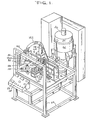
- Figure 1 generally illustrates a system 20 embodying the principle- of the present invention.
- the cverall process to be disclosed is a semi-automatic one in that the operator of the system must initially place the substrates to be coated into the system manually and remove them after they have been coated. Otherwise, the process requires no operator interaction.
- the operator places a substrate 21 (Figure 13), which is hollow and open at both ends, on a shelf 22 within a substrate clamp 24, then pushes a start button 26 on a control panel 28.
- the substrate is secured by the clamp 24, transferred and lowered into a dip pan 30 which contains a charge of slurry material which is to be drawn up into the substrate.
- An initial low vacuum is imparted to the top of the substrate through a vacuum cone 32 and draws up the slurry in the dip pan to uniformly fill all cells after which a high vacuum is applied to coat the lower portion of the substrate.
- the substrate is then lifted out of the dip pan and rotated 180°. As this occurs, a second charge of slurry is placed into the dip pan.
- the substrate 21 is then lowered back into the dip pan and the sequenced vacuum reapplied to draw up the second charge of slurry into the opposite end of the substrate.
- the substrate is then lifted out of the dip pan, rotated back 180 0 to its original position and brought back to the shelf 22.
- the clamp then releases the coated substrate and the operator removes it from the system by hand.
- slurry tank and circulation subsystems Figure 6, slurry metering subsystem: Figures 7-10; vacuum subsystem: Figures 1-5 and 11; mechanical handling subsystem: Figures 1-5, 13 and 14; and control subsystem: Figures 1-5, 12 and 14.
- FIG. 6 is a schematic representation of a slurry tank 34 and its associated circulation subsystem 35 which is utilized by the system 20.
- the tank may be of any suitable size or construction, but it is preferably fabricated as a plastic or fiberglass lined or coated stainless steel container and formed with a jacket 36 for cooling water or other suitable fluid to maintain the slurry at a controlled temperature.
- a typical size of the slurry tank which has been utilized has a capacity of approximately 48 gallons of the slurry.
- the tank is preferably formed with a bottom 37 having a moderately angled slope, 5°, for example, in the direction of an outlet 38.
- the slope on the tank bottom 36 is intended to direct the solids in the slurry, if they are not fully dispersed, toward that side of the tank bottom which is nearest the outlet 38. This insures that a slurry rich in solids is brought to a recirculating diaphragm pump 40 which serves to cause flow of the slurry throughout the subsystem and, eventually, to the dip pan 30.
- a diaphragm pump 40 which performs adequately in the subsystem is a Sandpiper unit, model number SB1-A Type SN-I-A.
- the slurry tank 34 may be provided with an agitator 42 as further insurance in maintaining the uniform suspension of the solids within the slurry.
- Piping 44 for the subsystem can be of any suitable non-wetting material such as polyvinyl chloride (PVC) plastic pipe.
- PVC polyvinyl chloride
- pipe which has been found to be suitable is sold under the trademark "TYGON” and is distributed by Fisher Scientific Corporation.
- the non-wetting feature of the pipe assures that the system will not become clogged with resultant loss of costly slurry material.
- a pulsation damper 46 operates in a conventional manner in the subsystem to accommodate surges and provide uniform pressure throughout and thereby assure a constant rate of feed of slurry for the coating operation.
- An example of a damper which has satisfactory characteristics for the subsystem is one marketed under the trademark "Sandpiper", model TA-1-N-1-A, manufactured by Allen Pump Company of Cleveland, Ohio.
- the slurry metering subsystem which is supplied by the slurry tank 34 and its associated circulation subsystem is indicated generally at 48 in Figure 6. It serves to assure that proper control is maintained over the amount of slurry placed in the dip pan 30.
- a suitable metering subsystem is illustrated in Figure 7 and referred to by reference numeral 48A.
- the subsystem 48A includes an inverted bottle or bladder 50 which is suitably suspended from one end of a balance arm 52. Specifically, a screw 54 of nylon or other suitable material is threadedly engaged with the center of the bladder's top 56.
- a head of the screw 54 is slidably but snugly received in a suitable recess 58 provided in the underside of the balance arm and near its end.
- the screw 54 may be replaced by some other suitable fastener having a shank portion in some fashion engaged with the bladder.
- the bladder may even be molded to provide a similarly shaped but integral hanging device.
- the balance arm is notched in a central region of its underside, as at 60, to receive a hardened knife end 62 which is fixed on the structural framework 64 for the system 20.
- the bladder 50 is mounted from a location which is in line with its center of gravity and in a fashion which readily permits its insertion and removal, a distinct benefit for purposes of cleaning and replacement.
- a counterweight 66 is threadedly received on a stud 68 and serves to substantially balance the balance arm assembly about the knife edge 62 so as to initially null a load cell 70 whose operative finger 71 is sensitive to movement of the balance arm.
- the load cell 70 may have a digital readout (not shown), one example being that marketed under the trademark "Sensotec", Model 450D, Hi/Low Option, manufactured by Sensotec Corporation of Columbus, Ohio.
- a vibration dampener pad 72 preferably composed of a high density rubber or other suitable resilient material is applied to the balance arm so as to cushion the interface between the balance arm and the finger 71.
- the distance along the balance arm between the knife edge is 62 and the recess 58 from which the bladder 50 is suspended is preferably much greater than the distance between the knife edge and the point of contact of the finger 71 with the pad 72. This serves to provide a mechanical amplification of the weight of the slurry to minimize the contribution of electrical noise created by the load cell 70.
- the subsystem 48A also includes an intake line 73 which extends from the piping 44 in the circulation subsystem and loosely through a hole in the top 56 of the bladder 50.
- An isolation valve 73A positioned in the intake like 73 can be operated as needed to allow work to he performed on the subsystem 48A.
- an outlet line 74 is connected to, and extends from the bottom of the bladder 50 and serves to direct flow of the slurry by way of gravity feed to the dip pan 30 via a surge accumulator 74A.
- the lines 73 and 74 are preferably composed of rubber tubing or other suitable flexible conduit material.
- a first normally closed feed valve 75 which is suitably mounted on the framework 64, and which may be a pinch valve operated by compressed air from an air line 75A as illustrated in Figure 7 or any other suitable type of valve, operates on the line 73 to regulate flow of slurry into the bladder 50.
- a second normally closed feed valve 77 is mounted on a bracket 76 which is bolted or otherwise suitably attached to the balance arm adjacent its first end and extends downwardly therefrom.
- the valve 77 may be a pinch valve operated by compressed air from an air line 77A.
- the valve 77 serves to regulate the flow of slurry in the line 74 out of the bladder 50 and toward the dip pan 30.
- the intake line 73 Since the upper feed valve 75 is fixed to the framework 64, the intake line 73 must have sufficient length and extend a sufficient distance into the bladder 50 to accommodate movement of the bladder as the balance arm 52 swings on the knife edge 62. Unlike the intake line 73, the outlet line 74 moves in a unitary fashion with the bladder 50 and the lower feed valve 77. The outlet line 74 discharges the slurry into the surge accumulator 74A positioned between the bladder and the dip pan 30. The surge accumulator 77A enables the bladder 50 to be refilled while flow of the slurry continues into the dip pan.
- a constant head of approximately 2 feet of the slurry is preferably maintained on the upper or first feed valve 75.
- the load cell 70 is nulled by reason of the counterweight 66.
- a digital signal from a computer 78 ( Figure 15) directs the upper feed valve 75 to open to start the operation of filling the bladder 50.
- the finger 71 of the load cell 70 is moved upwardly ( Figure 7) in accordance with counterclockwise movement of the balance arm 52 and causes a signal to be transmitted to the computer 78 to operate the feed valve 75 to close and thereby terminate the filling procedure.
- the feed valve 77 is operated, upon command, for that purpose.
- the surge accumulator 74A enables the bladder 50 to be refilled while flow of the slurry continues into the dip pan. It will also be appreciated that the construction just described provides a weighing system which has a minimum of drag as it moves and therefore assures a high degree of accuracy. The construction also assures a rapid rate of response due to integration of digital (computer 78) and analog (load cell 70) devices. That is, the upper feed valve 75 is closed by signal from the load cell 70, then held closed by the computer 78 until the computer commands it to be again opened. Thus, scan time errors inherent in a digital system are eliminated by analog monitoring.
- a metering pump 80 is employed. It may be, for example, a pump such as model number NP - 31 manufactured and marketed by Bran and Lubbe of Wheeling, Illinois.
- the bladder 50 may be the same as previously described with respect to subsystem 48A.
- a head of slurry is provided by piping 44 to the inlet of the metering pump 80.
- the outlet of the pump connect by way of an intake line 73 into the bladder 50, the line 73 being of a type similar to that used in the embodiment of Figure 7.
- the outlet line 74 also generally as previously described, suitably connects the bladder 50 with the dip pan 30.
- the bladder may be utilized to avoid splashing since the metering pump, by its nature, delivers slurry in spurts. However, it should be understood that it is not necessary to utilize the bladder 50 in the system in which event the metering pump would provide flow of the slurry directly into the dip pan.
- the particular type of metering pump referred to above is preferably provided with a mechanical control to manually determine, in a known fashion, the length of stroke of the pump. By so controlling the stroke, the amount of charge placed into the dip pan 30 can be controlled as previously noted.
- the system illustrated in Figure 8 thus is based on volume control of the charge in contrast to the weight control utilized in the embodiment of Figure 7.
- the dip pan may be fabricated in any appropriate fashion and out of any suitable material.
- One such suitable material which has been employed is a plastic material manufactured by General Electric Company and sold under the trademark "Delrin", the generic name being "acetal”.
- the dip pan comprises a main body 82 in which is form a cavity 84 for receiving an end of the substrate. Also a plurality of suitable holes 86 are formed for releasably mounting it on a base 87 which, in turn, is fixed on the structural framework 64 of the system 20. In this manner, one main body 82 can be substituted for another according to the size of the cavity 84 in order to accommodate various sizes and contours of substrates.
- the dip pan 30 be fabricated of a non-wettable material, of which Delrin is an example. As with the piping 44, use of such material serves to avoid adherence of the costly slurry material after the draw up operation has been completed.
- Delrin has been mentioned as one suitable material, in actuality, any relatively non-wettable material with good dimensional stability can be used. Other such materials might be from the families of polystyrene and polypropylene.
- a non-wettable material is preferred, if a material chosen is slightly wetting, the first charge of slurry will serve to competely wet the cavity 84 and, once wetted, the entire amount of subsequent charges of slurry into the dip pan will be received on the substrate.
- the cavity 84 of the dip pan is preferably of a similar shape for convenience as well as for conservation of the slurry.
- the cavity 84 of the dip pan 30 is illustrated as having a clearance around the outer periphery of the substrate such that the substrate can be easily received within the cavity. Nevertheless, the position of the substrate is not critical and the process can be properly performed even if the substrate is closer to one side of the cavity than to the other. In practice, however, it has been found desirable to hold the end of the substrate 21 at a nominal distance of 0.040 inches (approx. 1.0 mm) above the bottom of the cavity 84 (see Figure 11).
- the gap between the end of the substrate and the bottom of a cavity in the dip pan has a tolerance of plus or minus 0.010 inches (approx. 0.25 mm) which is to say that the range of a preferred distance of the end of the substrate above the bottom of dip pan is between 0.030 inches (approx. 0.75 mm) and 0.050 inches (approx. 1.25 mm). As long as this gap tolerance is maintained, the end of the substrate need not be parallel with the bottom of the cavity of the pan.
- the periphery of the substance immersed in the slurry it is preferred to have the periphery of the substance immersed in the slurry to a depth of approximately 0.25 inch (approx. 6.4 mm). However, it is only necessary to have some slight amount of the periphery of the substrate covered by the slurry at the beginning of the draw up process.
- the process would not work because air around the lower end of the substrate rather than the slurry would be drawn up into the substrate.
- the high vacuum will assure that the slurry will continue to be drawn up into the substrate until no slurry remains in the cavity 84.
- a slurry inlet passageway 88 is formed in the main body 82 to receive an end of the outlet line 74 which communicates through a connecting aperture 90 with cavity 84.
- the passageway 88 and its associated connecting aperture 90 are illustrated as being angled approximately 15° with respect to the bottom of the cavity 84. However, the magnitude of this angle is not a critical value but need only be sufficiently large to assure the flow of slurry into the bottom of the cavity.
- the aperture 90 is flared so as to prevent splashing of the slurry as it flows into the cavity 84.
- FIG 14 illustrates in detail a rotary index arm 92 and the substrate clamp 24 rotatably mounted at an end of the arm 92.
- the clamp 24 is generally disc-shaped and is formed with a centrally located opening 96 which extends totally through the clamp from its first, now bottom, side 98 through to its second, now top side 100.
- the substrate is shown in phantom extending through the opening 96 and being held by the clamp over the dip pan 30.
- the clamp 24 holds the substrate by means of an inflatable gasket 102 which is suitably attached thereto within the opening 96 and attached to the clamp 24 for movement between a deflated condition withdrawn from the substrate at an inflated state engaging and holding the substrate midway its ends.
- a pressurized air line 104 is suitably connected to a source of high pressure air and, by means of a fitting 106, serves to introduce pressurized air through the body of the clamp 24 into the gasket 102.
- air is fed to the inflatable gasket through the air line 104 to inflate it and securely hold the substrate while it is being processed.
- the air is released from the gasket and its is deflated. An operator then merely slips the coated substrate out of the clamp and replaces it with a new substrate to be coated.
- the substrate clamp 24 is mounted on a pair of carriages 108 and 110 for movement, respectively, along the horizontal or X axis and along the vertical or Z axis.
- a servo motor 112 appropriately rotates a lead screw 114 to drive the carriage 110 backwards and forwards along the horizontal axis.
- Cooperating with the lead screw 114 are a pair of Thompson rods 116 which are spaces apart and parallel to the lead screw 114 and attached at their ends to the structural framework 64.
- the Thompson rods 116 are slidingly received on the carriage 108 to maintain its orientation relative to the framework as it is moved to and fro.
- a servo motor 118 operates a lead screw 120 which is threadedly engaged with the carriage 110 to move it up and down.
- Thompson rods 122 are mounted at their ends to the horizontal carriage 108 and are parallel to the lead screw 120 and slidingly received on the vertical carriage 110 to assure its orientation as it moves upwardly and downwardly.
- the horizontal carriage 108 moves the clamp 24 from the region of the shelf 22 over to the region of the dip pan 30 and back again.
- the vertical carriage 110 operates to move the clamp up and down both above the shelf 22 and above the dip pan.
- the clamp 24 is rotatably mounted in a suitable manner on the rotary index arm 92.
- the index arm 92 is, in turn, integral with the vertical carriage 110.
- a cylindrical extension 124 of the clamp 24, that portion of the clamp which is rotatably mounted on the index arm 92, has a segment gear 126 fixed at its end distant from the region of the opening 96 in the clamp 24.
- a rack 128 which is slidably mounted on the index arm 92 engages the gear 126 and is operable by a pneumatic actuator 130 to move upwardly and downwardly, and by so doing, to rotate the clamp 24 so as to reverse the positions of the bottom side 98 and top side 100.
- a lug 132 is fixed to the outer wall of the cylindrical extension 124 and extends radially outwardly therefrom and serves as part of a mechanism for stopping rotation of the clamp 24 and holding it fixed at the positions desired.
- the lug 132 is selectably held in engagement with a stop member 132 which is rigidly mounted on the index arm 92.
- the clamp 24 lies in a substantially horizontal plan with the first side 98 being a bottom side and the second side 100 being a top side.
- the actuator 130 can be operated to rotate the extension 124, and with it the lug 132, until the lug engages another stop member 136 also fixed to the index arm 92 by at a diametrically opposed location relative to the extension 124.
- the lug 132 is illustrated in dotted lines in Figure 14.
- the clamp 24 will have been rotated to a position such that the first side 98 becomes the top side, and the second side 100 becomes the bottom side.
- operation of the gear 126 and rack 128 causing the lug 132 to first engage one stop member 134 and then the other stop member 136 serves to rotate the extension 124 through an arc of 180°.
- a substrate 21 is supported by the clamp 24, in one position of the clamp, one end of the substrate is oriented for reception within the cavity 84; and when the clamp is rotated 180° and held as just described, the opposite end of the substrate is then oriented for reception within the cavity.
- the vacuum cone 32 serves to engage the end of the substrate 21 and by applying a vacuum draws the slurry up into the substrate from the dip pan.
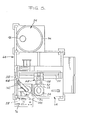
- Reference now to Figure 11 will aid in further understanding the construction of the vacuum cone. It is seen that a lower rim 138 of the vacuum cone 32 suitably mounts a seal gasket 140 which sealingly engages a side of the clamp 24 in such a fashion as to essentially prevent the loss of vacuum when the cone and clamp are engaged. From Figure 11 it is seen that when a substrate is placed into the clamp 24, it is substantially centered along its longitudinal axis. It is also noteworthy that while the system can utilize different sizes of clamps 24 and dip pans with different sizes of cavities 84, all to accommodate different sizes of substrates, the vacuum cone 32 is so configured by reason of its bell shape to generally accommodate all sizes of substrates.
- the vacuum cone 32 is connected via a line 142 to a source of vacuum.
- a preferred arrangement for the source of vacuum is a vacuum pump 144 driven by a variable speed motor. At a low motor speed, low vacuum is generated in the range of 1 - 1/2 to 2 inches (approx. 38 to 50 mm) of water at 0 cfm; and at a high motor speed, high vacuum is generated in the range of 6 to 7 inches (approx. 150 to 175 mm) of water at 200 cfm.
- the vacuum cone 32 is positioned above the dip pan 30, appropriately supported on the structural framework 64, and accurately aligned with the cavity 84.
- the vacuum cone can be moved along guides 146A between a raised or inactive position and a lowered or active position for engagement with the upper end of the substrate 21. Its raised position is defined when a cam 145A which is integral with and protrudes from the vacuum cone 32 strikes a limit switch 145 mounted on the exterior of the air cylinder 146 ( Figure 4). Operation of the switch 145 deactivates the air cylinder 146 while the computer 78 serves to deactivate the air cylinder when the vacuum cone reaches its lowered position engaging the substrate.
- the downward movement of the vacuum cone is effected by the air cylinder 146 in a coordinated fashion with movement of the clamp 24 as it carries a substrate toward the dip pan. That is, the vacuum cone 32 is moved downwardly simultaneously with the substrate at substantially the same time, or slightly before, that the substrate enters the slurry in the dip pan.
- FIG 13 generally illustrates an infrared sensor arrangement for controlling the height of the substrate 21 as it is placed into the dip pan with its lower end immersed in the slurry.
- the sensor arrangement incorporates a pair of sensor systems 147 each acting diagonally across the pan 30 and therefore across the path of movement of the substrate.
- Each sensor system contains a signal emitting source 148 and an associated detector 150, either a detector or a source being located in each corner of the pan.
- the sensor systems are commercially available units, one example being that sold under the trademark "Infra-Red Thru-Beam Switch" and manufactured by Balluff, Inc. of Florence, Kentucky.
- the purpose of the sensor systems is to determine when the lower end of the substrate approaches the pan and the charge held therein. Another purpose of the sensors and the reason for having two pairs of them, is to determine whether or not the substrate held in the clamp 24 is in a skewed position such that the end of the substrate would not properly enter the cavity 84. If such a situation were detected, the coating operation with respect to that substrate would be aborted and that particular substrate would be returned to the shelf 22 for repositioning by the operator. As the substrate approaches the dip pan upon downward movement of the clamp on the vertical carriage 110, its lower end activates the sensor system 147.
- the computer 78 ( Figure 15) takes over control of the further movement of the clamp to assure that the end of the substrate is held at the proper distance from the bottom of the dip pan and to regulate the point in which the high vacuum is placed on the substrate for the draw up operation.
- one sensor system 147 is adequate to determine whether a substrate is present and moving toward the dip pan. That is, as the substrate descends, it interrupts a signal emitted from the source 148 so that it is not received by the associated detector 150.
- two cooperating sensor systems are necessary to determine whether the substrate is properly oriented. Specifically, the two systems are so positioned ( Figure 12) such that the signals emitted and received by each detector are transverse to one another as well as to the path of travel of the substrate. In this manner, if the signals from both sources 148 to their associated detectors 150 are interrupted simultaneously, the computer 78 would be so informed and that would indicate that the substrate is properly oriented.
- the computer would understand that to mean that the substrate is not properly oriented for reception in the cavity 84. In that event, the computer can initiate appropriate alarms, perhaps audible, perhaps visual such as a light on the control panel 28, and cause operation of the system 20 to cease until the problem is corrected.
- the two sensor system operates in a similar fashion in event a sources 148 or detector 150 is accidentally splashed and coated with slurry thereby preventing it from functioning.
- the control subsystem for the system 20 generally comprises the start button 26 on the control panel 28 suitably mounted to the front of the framework 64, the computer 78 (Figure 15), the sensor systems 147 ( Figure 12), and numerous limit switches including 145 and others to be presented in the course of describing the operation of the system 20, below.
- One example of the computer 78 may be Model 2/15 sold under the trademark "Mini-PLC” by Allen-Bradley Company of Highland Heights, Ohio, which in fact, acts as the central processing unit (CPU) or brain of the system 20.
- the computer 78 receives information from the limit switches, sensor systems 14, and load cell 70 regarding the various stages of operation of the system and provides suitable instructions via an I/O interface 158 for operation for each of the subsystems in a proper, sequential manner.
- the operator manually loads the substrate to be coated into the substrate clamp 24 by placing its lower-most end on the shelf 22.
- the operator then pushes the start button 26 which simultaneously causes a number of operations to take place.
- a low vacuum is initially applied via line 142 to the vacuum cone 32.
- the slurry metering subsystem 48 meters a charge of slurry into the dip pan 30.
- the pneumatic actuator 130 is energized such that lug 132 is held firmly against stop member 134 thereby maintaining and firmly holding the substrate in its original orientation.
- pressurized air is introduced via the air line 104 to inflate the gasket 102 by which the clamp 24 firmly holds and supports the substrate.
- the vertical carriage 110 is driven upwardly on the vertical lead screw 120 about 0.25 inches (6.4 mm) off the top of the shelf 22 to raise the bottom of the substrate sufficiently to provide clearance for its subsequent horizontal movement.
- a limit switch 160 mounted on the carriage 110 engages a cam 161 mounted on the carriage 108 ( Figure 3)
- the horizontal lead screw 114 begins rotation to drive the horizontal carriage 108 horizontally to position it in alignment with the cavity 84 in the dip pan 30.
- a limit switch 162 suitably mounted on the framework 64 ( Figure 3) is provided to position the substrate over the dip pan as it moves from its position over the shelf 22 to its position over the dip pan.
- the limit switch 162 is aligned with the horizontal carriage 108 such that the outer surface of the carriage engages the switch at the point of extreme movement for the carriage. Actuation of the limit switch 162 not only serves to terminate rotation of horizontal lead screw 114, but also to initiate rotation, once again, of the vertical lead screw 120 to move the vertical carriage 110 downwardly and with it, the clamp 24 supporting the substrate. Actuation of the limit switch 162 also initiates downward movement of the vacuum cone 32.
- the motor is activated by the computer 78 to generate the low vacuum as previously described when the vacuum cone begins to descend.
- Movement of the vacuum cone and of the clamp supported substrate is coordinated such that when the lower end of the substrate enters the slurry in the dip pan, or slightly before, the vacuum cone seal- ingly envelopes the upper end of the substrate. This aids in evacuating the substrate before it reaches its terminal position.
- the further movement of the lower end of the substrate into the dip pan then becomes controlled by the computer 78 until brought to a position approximately 0.040 inches (approx. 1.0 mm) above the bottom of the cavity 84.
- the vacuum cone descends until it sealingly envelopes the upper end of the substrate.
- the low vacuum being applied to the vacuum cone 32 serves to draw the slurry up into the interior of the substrate. This process of drawing the slurry up into the interior of the substrate is sometimes referred to as "loading" of the slurry.
- the computer operates the motor to develop the high vacuum, as previously described, which is applied via the line 142 to the vacuum cone 32. It takes approximately one second for high vacuum to be developed and such operation continues for a sufficiently long duration to enable the slurry in the dip pan to be drawn completely up into the lower portion of the substrate.
- the purpose of loading the slurry using two levels of vacuum is to avoid "spiking" of the coating slurry in the interior passageways of the substrate. Spiking is a phenomenon which occurs when the initial vacuum applied is too high and the slurry is therefore not drawn uniformly up into the cells of the substrate.
- the vertical lead screw 120 is again operated to drive the vertical carriage 110 and the clamp 24 upwardly and away from the dip pan. Even as this occurs, however, the vacuum cone 32 continues to be engaged with the clamp and connected to the high vacuum source. In this manner, air is drawn through the substrate to thereby drawn the slurry which has just been deposited at the lower end of the substrate deeper into the interior thereof and to coat evenly all the cells of the substrate.
- This continued application of high vacuum to the substrate is referred to as a "spreading" or “distribution” step and continues for approximately 3 to 4 seconds, substantially the duration required for the clamp to reach a dwell position.
- the clamp is raised for this operation in order to permit rotation of the substrate as will be described below and to eliminate any obstruction that the dip pan or other equipment in its vicinity would create preventing the flow of air into the lowermost end of the substrate.
- a second charge of slurry destined to be loaded through the opposite end of the substrate, is dispensed and received within the cavity 84 of the dip pan 30.
- both ends of the substrate are clear, respectively, of the dip pan 30 and of the vacuum cone 32 enabling the next step to be performed, that is, the 180° rotation of the substrate.
- the ends of the substrate are reoriented, the previous lower end now being an upper end and the previous upper end now being a lower end.
- the clamp 24 and its supported substrate are moved and held in the new position by the actuator 130, the lug 132 now engaging the stop member 136.
- the clamp continues to be held in that position by the actuator 130 until the computer 78 instructs it to return to its original position at a later time in the process.
- the computer 78 again takes over operation of the system to move the substrate downwardly toward the cavity 84.
- the procedure previously described with respect to loading of the first end of the substrate is now repeated with second end.
- the clamp 24 together with the vacuum cone 32 is once again raised to its uppermost position over the dip pan 30, its upward movement again terminated by reason of the limit switch 164.
- the vacuum cone 32 is disengaged from the clamp 24 and returns to its home position as defined by the limit switch 145.
- the limit switch 164 also serves to cause operation of the pneumatic actuator 130 to again rotate the clamp 24, returning the substrate to its original position. Thereupon, the horizontal lead screw 114 is again operated to translate the clamp from a position over the dip pan to a position over the shelf 22. Horizontal movement of the clamp 24 is terminated when a limit switch 166 suitably mounted on the carriage 108 engages a cam 167 fixed to the framework 64. See Figures 3 and 4. This, in turn, activates the vertical lead screw 120 to lower the clamp 24 and, with it, the substrate such that its lower end is returned to the shelf with its original orientation.
- a limit switch 168 mounted on the carriage 110 engages a cam 170 fixed on the carriage 110 which serves to deenergize the system 20 and all of its subsystems.
- pressure to the gasket 102 is removed enabling the gasket 102 to deflate and be withdrawn from engagement with the substrate.
- the operator can then remove the coated substrate from the clamp and put an uncoated substrate back into the clamp for another cycle of the loading process.
- the entire procedure as described for coating of a single substrate takes approximately 30 to 40 seconds of time.
Landscapes
- Chemical & Material Sciences (AREA)
- Engineering & Computer Science (AREA)
- Materials Engineering (AREA)
- Organic Chemistry (AREA)
- Chemical Kinetics & Catalysis (AREA)
- Catalysts (AREA)
- Coating Apparatus (AREA)
- Elimination Of Static Electricity (AREA)
- Preparation Of Compounds By Using Micro-Organisms (AREA)
- Application Of Or Painting With Fluid Materials (AREA)
Abstract
Description
- This invention relates to a method and apparatus for the impregnation of ceramic monolithic substrates and, more particularly, to such a method and apparatus which enable the impregnation of the substrate with a predetermined amount of catalyst in an efficient manner and without waste.
- The need to remove or convert the noxious components in vehicular exhaust gases is now well known as a means for overcoming air pollution. Also, the present and proposed future requirements for having catalytic exhaust gas converters on motor vehicles are quite well known. One form in which the catalyst for the converters is supplied is as catalytically coated rigid skeletal monolithic substrates, or honeycomb-type elements which are generally cylindrical or oval in shape, where there are a multiplicity of longitudinal passageways in each unit in order to provide a high surface area.
- The rigid, monolithic, skeletal substrate structures are typically fabricated from ceramics which comprise refractory crystalline materials such as sillimanite, magnesium silicates, zircon, petalite, spodumene, cordierite, aluminosilicates, mullite, or combinations thereof. Such materials are generally considered to have a porous surface, but to improve the porosity of the surfaces of the skeletal surface, it is generally advisable to provide a highly porous alumina coating over the skeletal structure prior to effecting surface impregnation with a catalytically active material. These monolithic, substantially catalytically inactive skeletal substrate members have been described in prior art patents, as for example in Keith et al U.S. patent numbers 3,331,787 and 3,565,830, such that it is not deemed necessary to describe them in detail herein.
- Typically, and by way of example only, the catalytic component will comprise one or more of the noble and base metals and metal oxides of Groups IB, VB, VIIB, and VIII of the Periodic Table, particularly, copper, vanadium, chromium, manganese, iron, cobalt, nickel, platinum, palladium, rhodium, and ruthenium, with one catalytic metal being used singly or in combination with one or more other active metals.
- While various methods are known in the art for coating a monolithic support with a refractory coating such as alumina and noble metal catalytic coatings such as platinum, palladium, and rhodium, such methods from the standpoint of cost are deficient in minimizing the amount of coating applied, especially when a cost catalytically active precious metal, e.g. platinum, palladium, or rhodium is codeposited with the high surface area refractory metal.
- The instant disclosure reflects the results of continued efforts toward improving the techniques disclosed in copending application of Thomas Shimrock, et al, Serial Number 596,993, filed April 5, 1984. That disclosure first presented the need in the art for precisely controlling the amount of alumina and metal catalyst slurries applied to ceramic monolithic catalyst substraing to reduce the amount of excess coating required so that there may result an improvement in(51) efficiency of the process and a reduction in coating material loss.

- That copending disclosure listed a number of prior patents and their deficiencies in achieving the goals sought by the present invention. Some additional prior patents should be considered which bear a relationship to the present disclosure. For example, U.S. 3,984,213 to Hoyer et al discloses a treating chamber for applying a coating slurry to a substrate. The slurry is introduced from the top and flows downwardly through the hollow substrate.
- U.S. 4,038,939 to Hoyer et al discloses a process of impregnating a substrate by immersion within a treating chamber. It utilizes removal arm means which operate to effect a 90-degree turn of each substrate as it is removed from the treating chamber such that its honeycomb passageways are oriented in a generally horizontal manner to enable air blowing and drying of wet elements and to preclude slurry droplets from blocking the passageways.
- According to U.S. 4,191,126 to Reed et al, slurry is applied to a substrate either by dip coating or by applying a coating charge to the upper end of the substrate. It is mentioned in the patent that it may be advantageous, after the substrate has been purged from one end, to invert the substrate and continue the purge from the opposite end.
- In U.S. 4,384,014 to Young, there is a disclosure of impregnating a porous article placed on a base plate and covered with a cylinder sealingly mounted on the base plate in the manner of a bell jar. Vacuum is applied to the upper part of the cylinder and impregnant is admitted through the base plate under the action of the vacuum. When the process is completed, the vacuum is broken, excess impregnant is removed from the cover, and the cover is removed from the base plate.
- However, as previously mentioned, none of these prior patents discloses any techniques for precisely controlling the amount of coating slurries applied to the substrate to thereby improve the efficiency of the process and reduce the coating material loss.
- The present invention meets these needs by providing a method and apparatus for vacuum coating ceramic substrate members with a slurry of refractory and/or catalyst metal components wherein precisely controlled, predetermined amounts of the slurry are metered for application to the ceramic monolithic substrate member. This eliminates the need for flooding the member with excess coating material and the previously necessary ancillary steps for removal of the excess coating material from the member. Thus, by using the process and apparatus of the present invention, it is possible to apply a uniform coating of the desired concentration of the refractory and catalyst metal components without the need for external coating removal or internal unplugging of the internal skeletal passageways of the ceramic monolithic substrate.
- According to the present invention, a hollow substrate to be treated and having opposed open ends is transferred from a rest position such that one end is lowered into a dip pan into which has been introduced a predetermined amount or charge of slurry material containing the precious metal. With the one end fully immersed in the slurry, a vacuum placed on the other end of the substrate draws all of the slurry from the dip pan to coat the lower portion of the substrate. Thereafter the substrate is raised from the dip pan, then rotated, and again lowered so that the other end is fully immersed in another predetermined charge of the slurry and the process is repeated. Thereupon, the substrate is raised from the dip pan, rotated to return it to its original orientation, and returned to its starting location.
- By the practice of the present invention, only the interior skeletal passageways of the monolithic substrate member are coated. No draining or purging of excess coating slurry from the substrate member is necessary nor is any pre-vacuum application step, such a pre-evacuation of air from a ceramic member, required. With the ceramic monolithic substrate member internally coated with a predetermined amount of the coating slurry, it may, thereafter, be passed to a drying and/or heat treating zone to effect high temperature curing of the coating. However, by reason of the limited amount of catalyst slurry utilized in the coating operation, an unplugging step is not a prerequisite to such heating step.
- In a preferred embodiment of the invention, it has been found advantageous that after one end of the substrate member has been subjected to vacuum impregnation with a portion of the coating slurry, generally between 50 and 85 percent of the total predetermined amount of slurry, to invert the substrate member and continue the vacuum impregnation from the opposite end. This has been found to speed up the impregnation process and materially improve the uniformity of the coating distribution on the interior skeletal passageway walls.
- The apparatus which serves to acheive the goals of the invention incorporates a number of unique features. One of these features is a control system comprised of a computer, sensors, and limit switches to assure that operations are performed on a timely basis and in a proper sequence.
- Another feature of the invention resides in the utilization of the tank containing the slurry. It is preferably fabricated of stainless steel which is plastic or fiberglass lined or coated for ease of flow of the slurry, and has a bottom portion which slopes toward the outlet to assure continuing flow of all of the solid material present in the slurry. Its contents are regularly agitated and its temperature is maintained within acceptable limits.
- Still another feature of the invention is the provision of a dip pan formed with a slurry receiving cavity preferably shaped to freely receive but closely conform to the shape, in cross section, of the substrate to be coated. Two different methods of introducing a predetermined charge of slurry into the dip pan are provided by the invention. In one instance, the magnitude of the predetermined charge is based on weight; in the other instance, it is based on volume.
- A particularly critical part of the operation disclosed involves positioning each end of a substrate within the dip pan such that it is immersed in the slurry but spaced a specific distance from the bottom of a cavity formed in the dip pan. As the substrate is lowered toward the dip pan, appropriate sensors detect the end of the substrate which is about to be immersed in the slurry. The sensors signal the computer which, in turn, stops movement of the substrate when the end immersed in the slurry is spaced a proper distance above the bottom of the cavity in the dip pan.
- Another feature of the invention resides in providing an appropriate mechanism for rotating the substrate after one end has been coated so as to orient the other end for the same coating procedure.
- Still another feature of the invention resides in providing a vacuum cone which is lowered onto the exposed end of the substrate as the latter is being immersed into the slurry. Immediately prior to the vacuum cone initially engaging the end of the substrate, a low vacuum is applied, first to evacuate the interest of the substrate, then to begin drawing the slurry upwardly, after which high vacuum is applied to complete the coating task. The coating task is completed as to an end of the substrate when all of the slurry in the dip pan has been withdrawn. In this fashion, waste of costly slurry is avoided.
- According to another feature of the invention, after the coating operations have been performed at both ends of the substrate, the substrate is rotated once again to return it to its original orientation. In this manner, the substrate will be properly returned to its original resting place or shelf without concern that it will strike the top of the shelf or drop down onto the shelf.
- Other and further features of the invention will become apparent from the following description taken in conjunction with the following drawings. It is to be understood that both the foregoing general description and the following detailed description are exemplary and explanatory but are not restrictive of the invention. The accompanying drawings which are incorporated in and constitute a part of this invention, illustrate one embodiment of the invention, and together with the description, served to explain the principles of the invention.
- In the drawings:
- Figure 1 is a perspective view of a production system embodying the principles of the present invention;
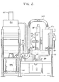
- Figure 2 is a side elevation view of one side of the system illustrated in Figure 1;
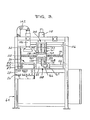
- Figure 3 is a front elevation view of the system illustrated in Figure 1, a part being cut away for improved visability;
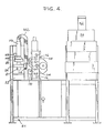
- Figure 4 is a side elevation view of the production system taken from the side opposite that illustration in Figure 2
- Figure 5 is a top plan view of the production system illustrated in Figures 1 - 4;
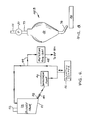
- Figure 6 is a schematic flow diagram of the slurry tank and circulation subsystem of the present invention;
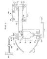
- Figures 7 and 8 are detail side elevation views, with certain parts shown schematically, illustrating different embodiments of the slurry metering subsystem;
- Figure 9 is a top plan view of the slurry dip pan utilized with the production systems of the present invention;
- Figure 10 is a cross section view taken generally along
line 10--10 in Figure 9; - Figure 11 is a detail side elevation view, certain parts being cut away and in section, illustrating a vacuum cone in an operative relationship with respect to a substrate which is in the process of being coated;
- Figure 12 is a detail top plan view of the dip pan Figures 9 and 10 illustrating the sensor devices associated therewith;
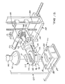
- Figure 13 is a perspective view illustrating the substrate clamp and the rotary index arm for rotating the substrate through an arc of 180 ;
- Figure 14 is a cross-section view taken generally along line 14--14 of Figure 13; and
- Figure 15 is a schematic representation of the control subsystem which operates the production system embodying the principles of the present invention.
- Refer now to the drawings, and initially to Figure 1 which generally illustrates a system 20 embodying the principle- of the present invention. For purposes of introduction, it is desirable to explain that the cverall process to be disclosed is a semi-automatic one in that the operator of the system must initially place the substrates to be coated into the system manually and remove them after they have been coated. Otherwise, the process requires no operator interaction.
- An overview of the process steps carried out by the system are as follows. The operator places a substrate 21 (Figure 13), which is hollow and open at both ends, on a
shelf 22 within asubstrate clamp 24, then pushes astart button 26 on acontrol panel 28. The substrate is secured by theclamp 24, transferred and lowered into adip pan 30 which contains a charge of slurry material which is to be drawn up into the substrate. An initial low vacuum is imparted to the top of the substrate through avacuum cone 32 and draws up the slurry in the dip pan to uniformly fill all cells after which a high vacuum is applied to coat the lower portion of the substrate. The substrate is then lifted out of the dip pan and rotated 180°. As this occurs, a second charge of slurry is placed into the dip pan. Thesubstrate 21 is then lowered back into the dip pan and the sequenced vacuum reapplied to draw up the second charge of slurry into the opposite end of the substrate. The substrate is then lifted out of the dip pan, rotated back 1800 to its original position and brought back to theshelf 22. The clamp then releases the coated substrate and the operator removes it from the system by hand. - While the overall system is generally illustrated in Figure 1, it can be better understood by referring to a number of subsystems and the figures which best depict each of them. Thus, the primary subsystems and the figures which best depict them are generally as follows: slurry tank and circulation subsystems: Figure 6, slurry metering subsystem: Figures 7-10; vacuum subsystem: Figures 1-5 and 11; mechanical handling subsystem: Figures 1-5, 13 and 14; and control subsystem: Figures 1-5, 12 and 14.
- Turn now to Figure 6 which is a schematic representation of a
slurry tank 34 and its associated circulation subsystem 35 which is utilized by the system 20. The tank may be of any suitable size or construction, but it is preferably fabricated as a plastic or fiberglass lined or coated stainless steel container and formed with ajacket 36 for cooling water or other suitable fluid to maintain the slurry at a controlled temperature. A typical size of the slurry tank which has been utilized has a capacity of approximately 48 gallons of the slurry. The tank is preferably formed with a bottom 37 having a moderately angled slope, 5°, for example, in the direction of anoutlet 38. The slope on thetank bottom 36 is intended to direct the solids in the slurry, if they are not fully dispersed, toward that side of the tank bottom which is nearest theoutlet 38. This insures that a slurry rich in solids is brought to arecirculating diaphragm pump 40 which serves to cause flow of the slurry throughout the subsystem and, eventually, to thedip pan 30. One example of adiaphragm pump 40 which performs adequately in the subsystem is a Sandpiper unit, model number SB1-A Type SN-I-A. Additionally, theslurry tank 34 may be provided with anagitator 42 as further insurance in maintaining the uniform suspension of the solids within the slurry. -
Piping 44 for the subsystem can be of any suitable non-wetting material such as polyvinyl chloride (PVC) plastic pipe. In actual practice, pipe which has been found to be suitable is sold under the trademark "TYGON" and is distributed by Fisher Scientific Corporation. The non-wetting feature of the pipe assures that the system will not become clogged with resultant loss of costly slurry material. - A
pulsation damper 46 operates in a conventional manner in the subsystem to accommodate surges and provide uniform pressure throughout and thereby assure a constant rate of feed of slurry for the coating operation. An example of a damper which has satisfactory characteristics for the subsystem is one marketed under the trademark "Sandpiper", model TA-1-N-1-A, manufactured by Allen Pump Company of Cleveland, Ohio. For optimum effectiveness of the subsystem, it is desirable to place a high head, preferably on the order of 2 feet (0.60 meters) on the circulation lines or piping 44 between thediaphragm pump 40 and theslurry tank 34. In this manner, the circulation lines or piping remain filled with slurry to prevent the drawing of air in the system which undesirably causes the formation of foam. - The slurry metering subsystem which is supplied by the
slurry tank 34 and its associated circulation subsystem is indicated generally at 48 in Figure 6. It serves to assure that proper control is maintained over the amount of slurry placed in thedip pan 30. One example of a suitable metering subsystem is illustrated in Figure 7 and referred to byreference numeral 48A. This can be termed a weight subsystem, that is, one which measures an appropriate weight for a charge to be introduced into thedip pan 30. As illustrated, thesubsystem 48A includes an inverted bottle orbladder 50 which is suitably suspended from one end of abalance arm 52. Specifically, ascrew 54 of nylon or other suitable material is threadedly engaged with the center of the bladder's top 56. A head of thescrew 54 is slidably but snugly received in asuitable recess 58 provided in the underside of the balance arm and near its end. Of course, it will be appreciated that thescrew 54 may be replaced by some other suitable fastener having a shank portion in some fashion engaged with the bladder. Indeed, the bladder may even be molded to provide a similarly shaped but integral hanging device. In turn, the balance arm is notched in a central region of its underside, as at 60, to receive ahardened knife end 62 which is fixed on thestructural framework 64 for the system 20. Thus, thebladder 50 is mounted from a location which is in line with its center of gravity and in a fashion which readily permits its insertion and removal, a distinct benefit for purposes of cleaning and replacement. - At the opposite end of the balance arm 20, a
counterweight 66 is threadedly received on astud 68 and serves to substantially balance the balance arm assembly about theknife edge 62 so as to initially null a load cell 70 whoseoperative finger 71 is sensitive to movement of the balance arm. The load cell 70 may have a digital readout (not shown), one example being that marketed under the trademark "Sensotec", Model 450D, Hi/Low Option, manufactured by Sensotec Corporation of Columbus, Ohio. Avibration dampener pad 72, preferably composed of a high density rubber or other suitable resilient material is applied to the balance arm so as to cushion the interface between the balance arm and thefinger 71. In this context, it is also noteworthy that the distance along the balance arm between the knife edge is 62 and therecess 58 from which thebladder 50 is suspended (representing the center of gravity of the bladder), is preferably much greater than the distance between the knife edge and the point of contact of thefinger 71 with thepad 72. This serves to provide a mechanical amplification of the weight of the slurry to minimize the contribution of electrical noise created by the load cell 70. - The
subsystem 48A also includes anintake line 73 which extends from the piping 44 in the circulation subsystem and loosely through a hole in the top 56 of thebladder 50. Anisolation valve 73A positioned in the intake like 73 can be operated as needed to allow work to he performed on thesubsystem 48A. Similarly, anoutlet line 74 is connected to, and extends from the bottom of thebladder 50 and serves to direct flow of the slurry by way of gravity feed to thedip pan 30 via asurge accumulator 74A. Thelines feed valve 75, which is suitably mounted on theframework 64, and which may be a pinch valve operated by compressed air from anair line 75A as illustrated in Figure 7 or any other suitable type of valve, operates on theline 73 to regulate flow of slurry into thebladder 50. In a similar fashion, a second normally closedfeed valve 77 is mounted on abracket 76 which is bolted or otherwise suitably attached to the balance arm adjacent its first end and extends downwardly therefrom. As withfeed valve 75, thevalve 77 may be a pinch valve operated by compressed air from anair line 77A. Thevalve 77 serves to regulate the flow of slurry in theline 74 out of thebladder 50 and toward thedip pan 30. Another benefit of the high head between theslurry tank 34 and thediaphragm pump 40, as mentioned above, is to assure that thebladder 50 be filled in a minimum of time so as to achieve a minimum of total cycle time. - Since the
upper feed valve 75 is fixed to theframework 64, theintake line 73 must have sufficient length and extend a sufficient distance into thebladder 50 to accommodate movement of the bladder as thebalance arm 52 swings on theknife edge 62. Unlike theintake line 73, theoutlet line 74 moves in a unitary fashion with thebladder 50 and thelower feed valve 77. Theoutlet line 74 discharges the slurry into thesurge accumulator 74A positioned between the bladder and thedip pan 30. Thesurge accumulator 77A enables thebladder 50 to be refilled while flow of the slurry continues into the dip pan. - With continued reference to Figure 7, a constant head of approximately 2 feet of the slurry is preferably maintained on the upper or
first feed valve 75. When it is desired to fill thebladder 50 with slurry, the load cell 70 is nulled by reason of thecounterweight 66. Thereupon, a digital signal from a computer 78 (Figure 15) directs theupper feed valve 75 to open to start the operation of filling thebladder 50. As the slurry is received in the bladder, thefinger 71 of the load cell 70 is moved upwardly (Figure 7) in accordance with counterclockwise movement of thebalance arm 52 and causes a signal to be transmitted to thecomputer 78 to operate thefeed valve 75 to close and thereby terminate the filling procedure. Subsequently, at such time that it is desired to release the contents of thebladder 50 into thedip pan 30, thefeed valve 77 is operated, upon command, for that purpose. - The
surge accumulator 74A enables thebladder 50 to be refilled while flow of the slurry continues into the dip pan. It will also be appreciated that the construction just described provides a weighing system which has a minimum of drag as it moves and therefore assures a high degree of accuracy. The construction also assures a rapid rate of response due to integration of digital (computer 78) and analog (load cell 70) devices. That is, theupper feed valve 75 is closed by signal from the load cell 70, then held closed by thecomputer 78 until the computer commands it to be again opened. Thus, scan time errors inherent in a digital system are eliminated by analog monitoring. - Another embodiment of a slurry metering subsystem is indicated by reference numeral 48B and illustrated in Figure S. For purposes of this embodiment, a
metering pump 80 is employed. It may be, for example, a pump such as model number NP - 31 manufactured and marketed by Bran and Lubbe of Wheeling, Illinois. Thebladder 50 may be the same as previously described with respect tosubsystem 48A. As illustrated in Figure 8, a head of slurry is provided by piping 44 to the inlet of themetering pump 80. The outlet of the pump connect by way of anintake line 73 into thebladder 50, theline 73 being of a type similar to that used in the embodiment of Figure 7. Theoutlet line 74, also generally as previously described, suitably connects thebladder 50 with thedip pan 30. The bladder may be utilized to avoid splashing since the metering pump, by its nature, delivers slurry in spurts. However, it should be understood that it is not necessary to utilize thebladder 50 in the system in which event the metering pump would provide flow of the slurry directly into the dip pan. The particular type of metering pump referred to above is preferably provided with a mechanical control to manually determine, in a known fashion, the length of stroke of the pump. By so controlling the stroke, the amount of charge placed into thedip pan 30 can be controlled as previously noted. The system illustrated in Figure 8 thus is based on volume control of the charge in contrast to the weight control utilized in the embodiment of Figure 7. - Turn now to Figures 9 and 10 which illustrate the
dip pan 30, that container which receives the charge of slurry before it is drawn up into thesubstrate 21. The dip pan may be fabricated in any appropriate fashion and out of any suitable material. One such suitable material which has been employed is a plastic material manufactured by General Electric Company and sold under the trademark "Delrin", the generic name being "acetal". The dip pan comprises amain body 82 in which is form acavity 84 for receiving an end of the substrate. Also a plurality ofsuitable holes 86 are formed for releasably mounting it on a base 87 which, in turn, is fixed on thestructural framework 64 of the system 20. In this manner, onemain body 82 can be substituted for another according to the size of thecavity 84 in order to accommodate various sizes and contours of substrates. - It is preferred that the
dip pan 30 be fabricated of a non-wettable material, of which Delrin is an example. As with the piping 44, use of such material serves to avoid adherence of the costly slurry material after the draw up operation has been completed. Although Delrin has been mentioned as one suitable material, in actuality, any relatively non-wettable material with good dimensional stability can be used. Other such materials might be from the families of polystyrene and polypropylene. However, while a non-wettable material is preferred, if a material chosen is slightly wetting, the first charge of slurry will serve to competely wet thecavity 84 and, once wetted, the entire amount of subsequent charges of slurry into the dip pan will be received on the substrate. - Since substrates are generally produced with an oval cross section, the
cavity 84 of the dip pan is preferably of a similar shape for convenience as well as for conservation of the slurry. With particular reference to Figure 10, thecavity 84 of thedip pan 30 is illustrated as having a clearance around the outer periphery of the substrate such that the substrate can be easily received within the cavity. Nevertheless, the position of the substrate is not critical and the process can be properly performed even if the substrate is closer to one side of the cavity than to the other. In practice, however, it has been found desirable to hold the end of thesubstrate 21 at a nominal distance of 0.040 inches (approx. 1.0 mm) above the bottom of the cavity 84 (see Figure 11). This ensures that, with a charge of the proper magnitude, the substrate periphery will be immersed to a maximum of about 0.25 inch (approx. 6.4 mm) in the slurry once the substrate has reached its draw up position. The gap between the end of the substrate and the bottom of a cavity in the dip pan has a tolerance of plus or minus 0.010 inches (approx. 0.25 mm) which is to say that the range of a preferred distance of the end of the substrate above the bottom of dip pan is between 0.030 inches (approx. 0.75 mm) and 0.050 inches (approx. 1.25 mm). As long as this gap tolerance is maintained, the end of the substrate need not be parallel with the bottom of the cavity of the pan. - Although noted above, it is preferred to have the periphery of the substance immersed in the slurry to a depth of approximately 0.25 inch (approx. 6.4 mm). However, it is only necessary to have some slight amount of the periphery of the substrate covered by the slurry at the beginning of the draw up process. Of course, it will be appreciated that if the end of the substrate were not immersed in the slurry, and there was no contact between the slurry and the peripheral edge of the substrate, the process would not work because air around the lower end of the substrate rather than the slurry would be drawn up into the substrate. However, with just a small portion of the end of the substrate immersed in the slurry, the high vacuum will assure that the slurry will continue to be drawn up into the substrate until no slurry remains in the
cavity 84. - As particularly well seen in Figure 10, a
slurry inlet passageway 88 is formed in themain body 82 to receive an end of theoutlet line 74 which communicates through a connectingaperture 90 withcavity 84. Thepassageway 88 and its associated connectingaperture 90 are illustrated as being angled approximately 15° with respect to the bottom of thecavity 84. However, the magnitude of this angle is not a critical value but need only be sufficiently large to assure the flow of slurry into the bottom of the cavity. Furthermore, theaperture 90 is flared so as to prevent splashing of the slurry as it flows into thecavity 84. - Turn now to Figure 14 which illustrates in detail a
rotary index arm 92 and thesubstrate clamp 24 rotatably mounted at an end of thearm 92. Theclamp 24 is generally disc-shaped and is formed with a centrally located opening 96 which extends totally through the clamp from its first, now bottom,side 98 through to its second, nowtop side 100. The substrate is shown in phantom extending through theopening 96 and being held by the clamp over thedip pan 30. Theclamp 24 holds the substrate by means of aninflatable gasket 102 which is suitably attached thereto within theopening 96 and attached to theclamp 24 for movement between a deflated condition withdrawn from the substrate at an inflated state engaging and holding the substrate midway its ends. - A
pressurized air line 104 is suitably connected to a source of high pressure air and, by means of a fitting 106, serves to introduce pressurized air through the body of theclamp 24 into thegasket 102. When the system is initially activated, air is fed to the inflatable gasket through theair line 104 to inflate it and securely hold the substrate while it is being processed. At such time that the substrate has completed its processing and is being return to its original position, the air is released from the gasket and its is deflated. An operator then merely slips the coated substrate out of the clamp and replaces it with a new substrate to be coated. - Refer once again to Figures 1, 3 and 5 in which it is shown that the
substrate clamp 24 is mounted on a pair ofcarriages servo motor 112 appropriately rotates alead screw 114 to drive thecarriage 110 backwards and forwards along the horizontal axis. Cooperating with thelead screw 114 are a pair ofThompson rods 116 which are spaces apart and parallel to thelead screw 114 and attached at their ends to thestructural framework 64. TheThompson rods 116 are slidingly received on thecarriage 108 to maintain its orientation relative to the framework as it is moved to and fro. - In a similar fashion, a
servo motor 118 operates alead screw 120 which is threadedly engaged with thecarriage 110 to move it up and down. Similar in construction to that of thehorizontal carriage 108,Thompson rods 122 are mounted at their ends to thehorizontal carriage 108 and are parallel to thelead screw 120 and slidingly received on thevertical carriage 110 to assure its orientation as it moves upwardly and downwardly. - It will be appreciated that the
horizontal carriage 108 moves theclamp 24 from the region of theshelf 22 over to the region of thedip pan 30 and back again. Similarly, thevertical carriage 110 operates to move the clamp up and down both above theshelf 22 and above the dip pan. - When the first end of the substrate has been processed in the dip pan, it is raised by means of the
servo motor 118 andlead screw 120 to an appropriate position so that the substrate is competely clear of the dip pan. The substrate is then rotated on theclamp 24 to bring its other end into position to be lowered into the dip pan. The mechanism which performs this rotation is most clearly illustrated in Figures 13 and 14. - It was previously mentioned that the
clamp 24 is rotatably mounted in a suitable manner on therotary index arm 92. Theindex arm 92 is, in turn, integral with thevertical carriage 110. Acylindrical extension 124 of theclamp 24, that portion of the clamp which is rotatably mounted on theindex arm 92, has asegment gear 126 fixed at its end distant from the region of theopening 96 in theclamp 24. Arack 128 which is slidably mounted on theindex arm 92 engages thegear 126 and is operable by apneumatic actuator 130 to move upwardly and downwardly, and by so doing, to rotate theclamp 24 so as to reverse the positions of thebottom side 98 andtop side 100. - A
lug 132 is fixed to the outer wall of thecylindrical extension 124 and extends radially outwardly therefrom and serves as part of a mechanism for stopping rotation of theclamp 24 and holding it fixed at the positions desired. Specifically, as illustrated in both Figures 13 and 14, thelug 132 is selectably held in engagement with astop member 132 which is rigidly mounted on theindex arm 92. In this situation, theclamp 24 lies in a substantially horizontal plan with thefirst side 98 being a bottom side and thesecond side 100 being a top side. However, theactuator 130 can be operated to rotate theextension 124, and with it thelug 132, until the lug engages anotherstop member 136 also fixed to theindex arm 92 by at a diametrically opposed location relative to theextension 124. - To illustrate this range of movements, the
lug 132 is illustrated in dotted lines in Figure 14. When thelug 132 engages thestop member 136, theclamp 24 will have been rotated to a position such that thefirst side 98 becomes the top side, and thesecond side 100 becomes the bottom side. In this manner, operation of thegear 126 andrack 128 causing thelug 132 to first engage onestop member 134 and then theother stop member 136 serves to rotate theextension 124 through an arc of 180°. Thus, when asubstrate 21 is supported by theclamp 24, in one position of the clamp, one end of the substrate is oriented for reception within thecavity 84; and when the clamp is rotated 180° and held as just described, the opposite end of the substrate is then oriented for reception within the cavity. - It was previously mentioned that the
vacuum cone 32 serves to engage the end of thesubstrate 21 and by applying a vacuum draws the slurry up into the substrate from the dip pan. Reference now to Figure 11 will aid in further understanding the construction of the vacuum cone. It is seen that alower rim 138 of thevacuum cone 32 suitably mounts aseal gasket 140 which sealingly engages a side of theclamp 24 in such a fashion as to essentially prevent the loss of vacuum when the cone and clamp are engaged. From Figure 11 it is seen that when a substrate is placed into theclamp 24, it is substantially centered along its longitudinal axis. It is also noteworthy that while the system can utilize different sizes ofclamps 24 and dip pans with different sizes ofcavities 84, all to accommodate different sizes of substrates, thevacuum cone 32 is so configured by reason of its bell shape to generally accommodate all sizes of substrates. - With particular reference to Figure 1, it is seen that the
vacuum cone 32 is connected via aline 142 to a source of vacuum. A preferred arrangement for the source of vacuum is avacuum pump 144 driven by a variable speed motor. At a low motor speed, low vacuum is generated in the range of 1 - 1/2 to 2 inches (approx. 38 to 50 mm) of water at 0 cfm; and at a high motor speed, high vacuum is generated in the range of 6 to 7 inches (approx. 150 to 175 mm) of water at 200 cfm. - As particularly well seen in Figures 1, 3 and 4, the
vacuum cone 32 is positioned above thedip pan 30, appropriately supported on thestructural framework 64, and accurately aligned with thecavity 84. By means of asuitable air cylinder 146, the vacuum cone can be moved alongguides 146A between a raised or inactive position and a lowered or active position for engagement with the upper end of thesubstrate 21. Its raised position is defined when acam 145A which is integral with and protrudes from thevacuum cone 32 strikes alimit switch 145 mounted on the exterior of the air cylinder 146 (Figure 4). Operation of theswitch 145 deactivates theair cylinder 146 while thecomputer 78 serves to deactivate the air cylinder when the vacuum cone reaches its lowered position engaging the substrate. The downward movement of the vacuum cone is effected by theair cylinder 146 in a coordinated fashion with movement of theclamp 24 as it carries a substrate toward the dip pan. That is, thevacuum cone 32 is moved downwardly simultaneously with the substrate at substantially the same time, or slightly before, that the substrate enters the slurry in the dip pan. - Turn now to Figure 13 which generally illustrates an infrared sensor arrangement for controlling the height of the
substrate 21 as it is placed into the dip pan with its lower end immersed in the slurry. The sensor arrangement incorporates a pair ofsensor systems 147 each acting diagonally across thepan 30 and therefore across the path of movement of the substrate. Each sensor system contains asignal emitting source 148 and an associateddetector 150, either a detector or a source being located in each corner of the pan. The sensor systems are commercially available units, one example being that sold under the trademark "Infra-Red Thru-Beam Switch" and manufactured by Balluff, Inc. of Florence, Kentucky. - The purpose of the sensor systems is to determine when the lower end of the substrate approaches the pan and the charge held therein. Another purpose of the sensors and the reason for having two pairs of them, is to determine whether or not the substrate held in the
clamp 24 is in a skewed position such that the end of the substrate would not properly enter thecavity 84. If such a situation were detected, the coating operation with respect to that substrate would be aborted and that particular substrate would be returned to theshelf 22 for repositioning by the operator. As the substrate approaches the dip pan upon downward movement of the clamp on thevertical carriage 110, its lower end activates thesensor system 147. At this point, the computer 78 (Figure 15) takes over control of the further movement of the clamp to assure that the end of the substrate is held at the proper distance from the bottom of the dip pan and to regulate the point in which the high vacuum is placed on the substrate for the draw up operation. - It will be appreciated that one
sensor system 147 is adequate to determine whether a substrate is present and moving toward the dip pan. That is, as the substrate descends, it interrupts a signal emitted from thesource 148 so that it is not received by the associateddetector 150. However, two cooperating sensor systems are necessary to determine whether the substrate is properly oriented. Specifically, the two systems are so positioned (Figure 12) such that the signals emitted and received by each detector are transverse to one another as well as to the path of travel of the substrate. In this manner, if the signals from bothsources 148 to their associateddetectors 150 are interrupted simultaneously, thecomputer 78 would be so informed and that would indicate that the substrate is properly oriented. However, if the signals are interrupted sequentially, for example, with a time differential of 100 milliseconds or more, the computer would understand that to mean that the substrate is not properly oriented for reception in thecavity 84. In that event, the computer can initiate appropriate alarms, perhaps audible, perhaps visual such as a light on thecontrol panel 28, and cause operation of the system 20 to cease until the problem is corrected. The two sensor system operates in a similar fashion in event asources 148 ordetector 150 is accidentally splashed and coated with slurry thereby preventing it from functioning. - The control subsystem for the system 20 generally comprises the
start button 26 on thecontrol panel 28 suitably mounted to the front of theframework 64, the computer 78 (Figure 15), the sensor systems 147 (Figure 12), and numerous limit switches including 145 and others to be presented in the course of describing the operation of the system 20, below. One example of thecomputer 78 may be Model 2/15 sold under the trademark "Mini-PLC" by Allen-Bradley Company of Highland Heights, Ohio, which in fact, acts as the central processing unit (CPU) or brain of the system 20. Thecomputer 78 receives information from the limit switches, sensor systems 14, and load cell 70 regarding the various stages of operation of the system and provides suitable instructions via an I/O interface 158 for operation for each of the subsystems in a proper, sequential manner. - The structure of the system 20 having been disclosed, its operation will now be described.
- At the outset, the operator manually loads the substrate to be coated into the
substrate clamp 24 by placing its lower-most end on theshelf 22. The operator then pushes thestart button 26 which simultaneously causes a number of operations to take place. A low vacuum is initially applied vialine 142 to thevacuum cone 32. At the same time, theslurry metering subsystem 48 meters a charge of slurry into thedip pan 30. Additionally, thepneumatic actuator 130 is energized such thatlug 132 is held firmly againststop member 134 thereby maintaining and firmly holding the substrate in its original orientation. Also, pressurized air is introduced via theair line 104 to inflate thegasket 102 by which theclamp 24 firmly holds and supports the substrate. - With these initial operations accomplished, the
vertical carriage 110 is driven upwardly on thevertical lead screw 120 about 0.25 inches (6.4 mm) off the top of theshelf 22 to raise the bottom of the substrate sufficiently to provide clearance for its subsequent horizontal movement. When alimit switch 160 mounted on thecarriage 110 engages acam 161 mounted on the carriage 108 (Figure 3), further movement in the vertical direction is halted but thehorizontal lead screw 114 begins rotation to drive thehorizontal carriage 108 horizontally to position it in alignment with thecavity 84 in thedip pan 30. - A
limit switch 162, suitably mounted on the framework 64 (Figure 3) is provided to position the substrate over the dip pan as it moves from its position over theshelf 22 to its position over the dip pan. Thelimit switch 162 is aligned with thehorizontal carriage 108 such that the outer surface of the carriage engages the switch at the point of extreme movement for the carriage. Actuation of thelimit switch 162 not only serves to terminate rotation of horizontallead screw 114, but also to initiate rotation, once again, of thevertical lead screw 120 to move thevertical carriage 110 downwardly and with it, theclamp 24 supporting the substrate. Actuation of thelimit switch 162 also initiates downward movement of thevacuum cone 32. The motor is activated by thecomputer 78 to generate the low vacuum as previously described when the vacuum cone begins to descend. Movement of the vacuum cone and of the clamp supported substrate is coordinated such that when the lower end of the substrate enters the slurry in the dip pan, or slightly before, the vacuum cone seal- ingly envelopes the upper end of the substrate. This aids in evacuating the substrate before it reaches its terminal position. - As the lower end of the downwardly moving substrate passes through the plane of the
sensor systems 147, and activates them, the further movement of the lower end of the substrate into the dip pan then becomes controlled by thecomputer 78 until brought to a position approximately 0.040 inches (approx. 1.0 mm) above the bottom of thecavity 84. At the same time, as just noted, the vacuum cone descends until it sealingly envelopes the upper end of the substrate. As the substrate is being immersed into the slurry, the low vacuum being applied to thevacuum cone 32 serves to draw the slurry up into the interior of the substrate. This process of drawing the slurry up into the interior of the substrate is sometimes referred to as "loading" of the slurry. Approximately 1 - 1/2 to 2 seconds after the substrate reaches its bottom or terminal position, which is approximately 1/2 second after the substrate enters the slurry, the computer operates the motor to develop the high vacuum, as previously described, which is applied via theline 142 to thevacuum cone 32. It takes approximately one second for high vacuum to be developed and such operation continues for a sufficiently long duration to enable the slurry in the dip pan to be drawn completely up into the lower portion of the substrate. The purpose of loading the slurry using two levels of vacuum is to avoid "spiking" of the coating slurry in the interior passageways of the substrate. Spiking is a phenomenon which occurs when the initial vacuum applied is too high and the slurry is therefore not drawn uniformly up into the cells of the substrate. A more detailed explanation is provided in copending patent application Serial No. 596,993 to which reference was made above. - After all of the slurry in the
dip pan 30 has been loaded into the substrate, thevertical lead screw 120 is again operated to drive thevertical carriage 110 and theclamp 24 upwardly and away from the dip pan. Even as this occurs, however, thevacuum cone 32 continues to be engaged with the clamp and connected to the high vacuum source. In this manner, air is drawn through the substrate to thereby drawn the slurry which has just been deposited at the lower end of the substrate deeper into the interior thereof and to coat evenly all the cells of the substrate. This continued application of high vacuum to the substrate is referred to as a "spreading" or "distribution" step and continues for approximately 3 to 4 seconds, substantially the duration required for the clamp to reach a dwell position. The clamp is raised for this operation in order to permit rotation of the substrate as will be described below and to eliminate any obstruction that the dip pan or other equipment in its vicinity would create preventing the flow of air into the lowermost end of the substrate. Simultaneously, a second charge of slurry, destined to be loaded through the opposite end of the substrate, is dispensed and received within thecavity 84 of thedip pan 30. - Upward movement of the
clamp 24 and thevacuum cone 30 as a unit is terminated when alimit switch 164 on thevertical carriage 110 engages acam 165 fixed on thecarriage 108. When the spreading or distribution step has been completed, approximately 5 to 10 seconds after initiation of the high vacuum operation, thecone 32 is disengaged from the upper end of the clamp and continues to be raised until it actuates the limit switch 145 (Figure 4) as previously described and comes to rest at its home position. As thevacuum cone 32 retreats to its home position, thecomputer 78 deactivates the motor thereby eliminating the presence of vacuum at the vacuum cone. - At this point, both ends of the substrate are clear, respectively, of the
dip pan 30 and of thevacuum cone 32 enabling the next step to be performed, that is, the 180° rotation of the substrate. When rotated, the ends of the substrate are reoriented, the previous lower end now being an upper end and the previous upper end now being a lower end. Theclamp 24 and its supported substrate are moved and held in the new position by theactuator 130, thelug 132 now engaging thestop member 136. The clamp continues to be held in that position by theactuator 130 until thecomputer 78 instructs it to return to its original position at a later time in the process. - With the uncoated end of the substrate now being in position to descend to the
dip pan 30, thecomputer 78 again takes over operation of the system to move the substrate downwardly toward thecavity 84. The procedure previously described with respect to loading of the first end of the substrate is now repeated with second end. Upon the completion of the loading and drying steps with respect to this second end of the substrate, theclamp 24 together with thevacuum cone 32 is once again raised to its uppermost position over thedip pan 30, its upward movement again terminated by reason of thelimit switch 164. Thereafter, thevacuum cone 32 is disengaged from theclamp 24 and returns to its home position as defined by thelimit switch 145. - The
limit switch 164 also serves to cause operation of thepneumatic actuator 130 to again rotate theclamp 24, returning the substrate to its original position. Thereupon, thehorizontal lead screw 114 is again operated to translate the clamp from a position over the dip pan to a position over theshelf 22. Horizontal movement of theclamp 24 is terminated when alimit switch 166 suitably mounted on thecarriage 108 engages a cam 167 fixed to theframework 64. See Figures 3 and 4. This, in turn, activates thevertical lead screw 120 to lower theclamp 24 and, with it, the substrate such that its lower end is returned to the shelf with its original orientation. As this occurs, alimit switch 168 mounted on the carriage 110 (Figures 3 and 4) engages acam 170 fixed on thecarriage 110 which serves to deenergize the system 20 and all of its subsystems. With the lower end of the substrate received on theshelf 22, pressure to thegasket 102 is removed enabling thegasket 102 to deflate and be withdrawn from engagement with the substrate. The operator can then remove the coated substrate from the clamp and put an uncoated substrate back into the clamp for another cycle of the loading process. The entire procedure as described for coating of a single substrate takes approximately 30 to 40 seconds of time. - While a preferred embodiment of the invention has been disclosed in detail, it should be understood by those skilled in the art that various modifications may be made to the illustrated embodiment without departing from the spirit and the scope thereof as described in the specification and defined in the appended claims.
Claims (49)
said apparatus including a second normally closed feed valve in said outlet line for controlling the flow of the slurry out of said bladder upon signal from said control means.
Priority Applications (1)
| Application Number | Priority Date | Filing Date | Title |
|---|---|---|---|
| AT86301418T ATE64873T1 (en) | 1985-02-28 | 1986-02-27 | METHOD OF APPLYING A PRE-DETERMINED QUANTITY OF A CATALYST TO THE INTERNAL SURFACE OF A HOLLOW SUBSTRATE. |
Applications Claiming Priority (2)
| Application Number | Priority Date | Filing Date | Title |
|---|---|---|---|
| US06/706,708 US4609563A (en) | 1985-02-28 | 1985-02-28 | Metered charge system for catalytic coating of a substrate |
| US706708 | 1985-02-28 |
Publications (3)
| Publication Number | Publication Date |
|---|---|
| EP0202733A2 true EP0202733A2 (en) | 1986-11-26 |
| EP0202733A3 EP0202733A3 (en) | 1988-07-06 |
| EP0202733B1 EP0202733B1 (en) | 1991-07-03 |
Family
ID=24838733
Family Applications (1)
| Application Number | Title | Priority Date | Filing Date |
|---|---|---|---|
| EP86301418A Expired - Lifetime EP0202733B1 (en) | 1985-02-28 | 1986-02-27 | Process for applying a predetermined amount of catalyst to the interior surfaces of a hollow substrate |
Country Status (8)
| Country | Link |
|---|---|
| US (1) | US4609563A (en) |
| EP (1) | EP0202733B1 (en) |
| JP (2) | JPH07106319B2 (en) |
| KR (1) | KR930002245B1 (en) |
| AT (1) | ATE64873T1 (en) |
| AU (2) | AU590541B2 (en) |
| CA (1) | CA1256088A (en) |
| DE (2) | DE3680025D1 (en) |
Cited By (7)
| Publication number | Priority date | Publication date | Assignee | Title |
|---|---|---|---|---|
| EP0428990A1 (en) * | 1989-11-16 | 1991-05-29 | N.E. Chemcat Corporation | Method and apparatus for liquid coating for honeycomb structure |
| US5516494A (en) * | 1994-03-17 | 1996-05-14 | Degussa Aktiengesellschaft | Process for applying a coating to honeycomb structures in an exhaust gas converter |
| US6599570B1 (en) | 1998-03-19 | 2003-07-29 | Johnson Matthey Public Limited Company | Monolith coating apparatus and method therefor |
| US7097880B2 (en) | 2003-12-18 | 2006-08-29 | Corning Incorporated | Method for preparing catalysts |
| WO2008011552A3 (en) * | 2006-07-21 | 2008-09-04 | Sub One Technology Inc | System and method for treating surfaces of components |
| EP1789190B1 (en) | 2004-08-21 | 2017-06-14 | Umicore AG & Co. KG | Method for coating a wall flow filter with a coating composition |
| CN108855787A (en) * | 2018-07-30 | 2018-11-23 | 孙传海 | Work piece inner surface impregnation and device |
Families Citing this family (95)
| Publication number | Priority date | Publication date | Assignee | Title |
|---|---|---|---|---|
| DE4040150A1 (en) * | 1990-02-28 | 1991-08-29 | Degussa | METHOD OF SUPPORTING CERAMIC WAVE BODIES WITH FINE-PARTIAL SOLIDS |
| FR2677641B1 (en) * | 1991-06-17 | 1994-01-28 | Propulsion Ste Europeenne | PROCESS FOR THE PREPARATION OF PARTS OF COMPOSITE MATERIAL WITH AN ALUMINA MATRIX. |
| AU637306B3 (en) * | 1992-10-05 | 1993-05-20 | David Bencich | Nozzle for caulking gun |
| JP3578291B2 (en) * | 1995-09-08 | 2004-10-20 | 日本軽金属株式会社 | Method and apparatus for applying brazing composition |
| WO1997026226A1 (en) * | 1996-01-18 | 1997-07-24 | Moltech Invent S.A. | Protection of porous bodies against oxidation |
| US20010026838A1 (en) * | 1996-06-21 | 2001-10-04 | Engelhard Corporation | Monolithic catalysts and related process for manufacture |
| IN195165B (en) * | 1996-06-21 | 2005-01-28 | Engelhard Corp | |
| US5953832A (en) * | 1998-04-28 | 1999-09-21 | Engelhard Corporation | Method for drying a coated substrate |
| JP3468056B2 (en) * | 1997-09-23 | 2003-11-17 | 東京エレクトロン株式会社 | Substrate detection device |
| WO1999034932A1 (en) * | 1998-01-09 | 1999-07-15 | Fastar, Ltd. | Moving head, coating apparatus and method |
| BR9909986A (en) * | 1998-04-28 | 2000-12-26 | Engelhard Corp | Monolithic catalysts and related process for manufacturing |
| DE19837731A1 (en) * | 1998-08-20 | 2000-02-24 | Degussa | Process for coating the flow channels of a monolithic catalyst carrier with a coating dispersion |
| US6478874B1 (en) | 1999-08-06 | 2002-11-12 | Engelhard Corporation | System for catalytic coating of a substrate |
| FR2803540B1 (en) * | 2000-01-12 | 2002-03-29 | Suez Lyonnaise Des Eaux | METHOD FOR ATTACHING AND IMMOBILIZING A CATALYST ON A SUPPORT |
| EP1273344B1 (en) * | 2001-06-30 | 2005-08-31 | Umicore AG & Co. KG | Process for the coating of a support |
| US7371352B2 (en) * | 2001-09-26 | 2008-05-13 | Siemens Power Generation, Inc. | Catalyst element having a thermal barrier coating as the catalyst substrate |
| US20030103875A1 (en) * | 2001-09-26 | 2003-06-05 | Siemens Westinghouse Power Corporation | Catalyst element having a thermal barrier coating as the catalyst substrate |
| US7541005B2 (en) * | 2001-09-26 | 2009-06-02 | Siemens Energy Inc. | Catalytic thermal barrier coatings |
| DE60218974T2 (en) * | 2002-01-02 | 2007-12-20 | Cataler Corp. | Apparatus for coating with a catalytic coating solution and method for producing a catalyst for the purification of exhaust gases |
| US20040001781A1 (en) | 2002-06-27 | 2004-01-01 | Engelhard Corporation | Multi-zone catalytic converter |
| US7521087B2 (en) * | 2002-08-27 | 2009-04-21 | Basf Catalysts Llc | Method for catalyst coating of a substrate |
| US7572311B2 (en) | 2002-10-28 | 2009-08-11 | Geo2 Technologies, Inc. | Highly porous mullite particulate filter substrate |
| US7574796B2 (en) | 2002-10-28 | 2009-08-18 | Geo2 Technologies, Inc. | Nonwoven composites and related products and methods |
| US7582270B2 (en) | 2002-10-28 | 2009-09-01 | Geo2 Technologies, Inc. | Multi-functional substantially fibrous mullite filtration substrates and devices |
| US6946013B2 (en) | 2002-10-28 | 2005-09-20 | Geo2 Technologies, Inc. | Ceramic exhaust filter |
| US6830079B1 (en) * | 2003-08-27 | 2004-12-14 | General Electric Company | Integrated apparatus and method for filling porous composite preforms |
| US20050054526A1 (en) * | 2003-09-08 | 2005-03-10 | Engelhard Corporation | Coated substrate and process of preparation thereof |
| CN1296146C (en) * | 2004-02-24 | 2007-01-24 | 中国科学院生态环境研究中心 | Method and equipment for coating slurry layer on cellular carrier of ceramics |
| DE102004051099A1 (en) * | 2004-10-19 | 2006-04-20 | Umicore Ag & Co. Kg | Method and device for coating a series of supporting bodies |
| US7451849B1 (en) | 2005-11-07 | 2008-11-18 | Geo2 Technologies, Inc. | Substantially fibrous exhaust screening system for motor vehicles |
| US7211232B1 (en) | 2005-11-07 | 2007-05-01 | Geo2 Technologies, Inc. | Refractory exhaust filtering method and apparatus |
| US7682578B2 (en) | 2005-11-07 | 2010-03-23 | Geo2 Technologies, Inc. | Device for catalytically reducing exhaust |
| US7682577B2 (en) | 2005-11-07 | 2010-03-23 | Geo2 Technologies, Inc. | Catalytic exhaust device for simplified installation or replacement |
| DE102005054945B3 (en) * | 2005-11-17 | 2007-02-15 | Süd-Chemie AG | Applying solvent containing coating medium on an exhaust gas cleaning catalyst carrier structure with an internal surface by the coating medium containing wash coat dispersion/gas mixture in a vacuum device |
| US7678416B2 (en) * | 2005-12-05 | 2010-03-16 | Cataler Corporation | Substrate coating method |
| US7722828B2 (en) | 2005-12-30 | 2010-05-25 | Geo2 Technologies, Inc. | Catalytic fibrous exhaust system and method for catalyzing an exhaust gas |
| US7444805B2 (en) | 2005-12-30 | 2008-11-04 | Geo2 Technologies, Inc. | Substantially fibrous refractory device for cleaning a fluid |
| US7563415B2 (en) | 2006-03-03 | 2009-07-21 | Geo2 Technologies, Inc | Catalytic exhaust filter device |
| DE102006038406A1 (en) * | 2006-08-17 | 2008-02-21 | Süd-Chemie AG | Process for coating or impregnating a catalyst support |
| US8006637B2 (en) * | 2007-03-29 | 2011-08-30 | Corning Incorporated | Method and apparatus for membrane deposition |
| JP4972578B2 (en) * | 2008-02-15 | 2012-07-11 | 東京濾器株式会社 | Method for producing exhaust gas purification catalyst |
| CN101301645B (en) * | 2008-07-01 | 2012-10-31 | 杨景秋 | Carrier catalyst slurry automatic coating machine |
| US9186662B2 (en) * | 2008-08-06 | 2015-11-17 | Basf Se | Positioning device and method with rotary indexing table for monolith-based automobile and chemical catalysts |
| US9144796B1 (en) * | 2009-04-01 | 2015-09-29 | Johnson Matthey Public Limited Company | Method of applying washcoat to monolithic substrate |
| FR2943928B1 (en) | 2009-04-02 | 2012-04-27 | Saint Gobain Ct Recherches | SIC-BASED FILTERING STRUCTURE HAVING IMPROVED THERMOMECHANICAL PROPERTIES |
| FR2949690B1 (en) | 2009-09-04 | 2011-10-21 | Saint Gobain Ct Recherches | SIC PARTICLE FILTER INCORPORATING CERIUM |
| GB201000019D0 (en) | 2010-01-04 | 2010-02-17 | Johnson Matthey Plc | Coating a monolith substrate with catalyst component |
| DE102010007499A1 (en) * | 2010-02-09 | 2011-08-11 | Umicore AG & Co. KG, 63457 | Volumetric coating arrangement |
| EP2537655B1 (en) * | 2010-12-07 | 2015-02-25 | Sumitomo Chemical Company Limited | Device for conveying honeycomb structural body, method for sealing honeycomb structural body, and method for producing honeycomb structural body |
| US20140363578A1 (en) | 2011-09-29 | 2014-12-11 | Heesung Catalysts Corporation | Apparatus and method for quantitatively coating catalyst support |
| DE102013104318A1 (en) * | 2013-04-29 | 2014-10-30 | Fredy Iseli | Coating device and coating method |
| KR101467404B1 (en) * | 2013-05-02 | 2014-12-03 | 희성촉매 주식회사 | A device for dosing a fixed catalyst amount |
| GB201311615D0 (en) * | 2013-06-03 | 2013-08-14 | Johnson Matthey Plc | Method of coating a substrate with a catalyst component |
| CN103386391B (en) * | 2013-07-23 | 2015-08-26 | 杨景秋 | The synchronous coated catalysts automatic machine of honeycomb substrate complex carries |
| CN104107783A (en) * | 2014-07-03 | 2014-10-22 | 无锡市霖蕾环保科技有限公司 | Six-station coating machine |
| EP3277424A4 (en) * | 2015-03-30 | 2019-05-01 | BASF Corporation | MULTIFUNCTIONAL COATING SYSTEM AND LAVIS CATALYTIC LAYER APPLICATION COATING MODULE AND / OR SOLUTION TO SUBSTRATE AND ASSOCIATED METHODS |
| DE102015207164B4 (en) * | 2015-04-21 | 2023-06-22 | Aktiebolaget Skf | Covering device for partially covering a bearing ring in a treatment bath and method for partially treating a bearing ring |
| US10020218B2 (en) | 2015-11-17 | 2018-07-10 | Applied Materials, Inc. | Substrate support assembly with deposited surface features |
| CN109789357B (en) * | 2016-09-30 | 2021-06-29 | 日立金属株式会社 | Method and apparatus for manufacturing ceramic honeycomb filter |
| EP3424596A1 (en) | 2017-07-06 | 2019-01-09 | Umicore Ag & Co. Kg | Method for coating a monolith carrier |
| EP3424595B1 (en) | 2017-07-06 | 2023-05-10 | Umicore Ag & Co. Kg | Coating apparatus and method |
| DE102017115138A1 (en) | 2017-07-06 | 2019-01-10 | Umicore Ag & Co. Kg | Contactless leveling of a washcoat suspension |
| DE102018100834A1 (en) | 2018-01-16 | 2019-07-18 | Umicore Ag & Co. Kg | Process for producing an SCR catalyst |
| DE102018100833A1 (en) | 2018-01-16 | 2019-07-18 | Umicore Ag & Co. Kg | Process for producing an SCR catalyst |
| DE102018108346A1 (en) | 2018-04-09 | 2019-10-10 | Umicore Ag & Co. Kg | Coated wall flow filter |
| DE102018110804B4 (en) | 2018-05-04 | 2024-06-27 | Umicore Ag & Co. Kg | Coated wall flow filter |
| DE102018111246A1 (en) | 2018-05-09 | 2019-11-14 | Umicore Ag & Co. Kg | Method for coating a wall-flow filter |
| KR102158603B1 (en) * | 2018-05-21 | 2020-09-22 | 희성촉매 주식회사 | Jig unit for catalyst support clamping |
| CN108906502A (en) * | 2018-07-18 | 2018-11-30 | 安徽亦宣金属科技有限公司 | A kind of device for handling public lipstick shell |
| CN109078801A (en) * | 2018-09-04 | 2018-12-25 | 深圳市科晶智达科技有限公司 | A kind of soaking coating appts |
| DE102018127955A1 (en) | 2018-11-08 | 2020-05-14 | Umicore Ag & Co. Kg | Catalytically active particle filter with high filtration efficiency |
| DE102018127957A1 (en) | 2018-11-08 | 2020-05-14 | Umicore Ag & Co. Kg | Particle filter with multiple coatings |
| DE102018127953B4 (en) | 2018-11-08 | 2025-03-20 | Umicore Ag & Co. Kg | Wall-flow filter with high filtration efficiency |
| JP6532622B1 (en) * | 2019-02-12 | 2019-06-19 | 千住金属工業株式会社 | Soldering method and soldering apparatus |
| KR102165633B1 (en) * | 2019-04-05 | 2020-10-14 | 희성촉매 주식회사 | Method for coating precise catalyst slurry on a catalytic filter for purifying exhaust gas |
| DE102019121084A1 (en) | 2019-08-05 | 2021-02-11 | Umicore Ag & Co. Kg | Catalyst substrates with porous coating |
| EP3834933B8 (en) * | 2019-12-10 | 2024-03-27 | Johnson Matthey Public Limited Company | Apparatus and method for coating substrates with washcoats |
| EP3834936B1 (en) | 2019-12-10 | 2022-06-29 | Johnson Matthey Public Limited Company | Apparatus and method for coating substrates with washcoats |
| DE102020103292A1 (en) | 2020-02-10 | 2021-08-12 | Umicore Ag & Co. Kg | Using ultrasound to clean wall flow filter substrates |
| DE102020131366A1 (en) | 2020-11-26 | 2022-06-02 | Umicore Ag & Co. Kg | Emission control system for stoichiometric combustion engines |
| EP4015064B1 (en) | 2020-12-15 | 2025-01-22 | Umicore AG & Co. KG | Catalytically active particle filter with high filtration efficiency |
| EP4015066A1 (en) | 2020-12-15 | 2022-06-22 | UMICORE AG & Co. KG | Catalytically active particle filter with high filtration efficiency |
| EP4015067A1 (en) | 2020-12-15 | 2022-06-22 | UMICORE AG & Co. KG | Catalytically active particle filter with high filtration efficiency |
| EP4015065B1 (en) | 2020-12-15 | 2025-02-26 | Umicore AG & Co. KG | Catalytically active particle filter with high filtration efficiency |
| DE102021107130B4 (en) | 2021-03-23 | 2022-12-29 | Umicore Ag & Co. Kg | Device for increasing the fresh filtration of petrol particle filters |
| DE102021125536A1 (en) | 2021-10-01 | 2023-04-06 | Umicore Ag & Co. Kg | Catalytically active particle filter with high filtration efficiency |
| EP4159310A1 (en) | 2021-10-01 | 2023-04-05 | UMICORE AG & Co. KG | Catalytic coating |
| JP7265605B1 (en) * | 2021-11-22 | 2023-04-26 | 株式会社キャタラー | Manufacturing method of exhaust gas purifying catalyst device |
| CN115010288B (en) * | 2022-01-11 | 2023-07-04 | 黄河水利职业技术学院 | Heavy metal processor containing adsorbent |
| DE202022000455U1 (en) | 2022-02-22 | 2022-03-02 | Umicore Ag & Co. Kg | coating hat |
| DE102022002854A1 (en) | 2022-08-05 | 2024-02-08 | Umicore Ag & Co. Kg | Catalytically active particle filter with high filtration efficiency and oxidation function |
| EP4424407A1 (en) | 2023-02-28 | 2024-09-04 | Umicore AG & Co. KG | Gpf with improved washcoat distribution |
| CN117399245A (en) * | 2023-11-03 | 2024-01-16 | 中铁十五局集团有限公司 | An anti-rust paint filling device for the inner wall of small-diameter metal pipes |
| DE102023132075A1 (en) * | 2023-11-17 | 2025-05-22 | Umicore Ag & Co. Kg | Catalytic particulate filter |
| DE102024121910B4 (en) | 2024-08-01 | 2026-04-02 | Umicore Ag & Co. Kg | Method for manufacturing a catalytically active particulate filter, catalytically active particulate filter, exhaust gas cleaning system and exhaust gas cleaning method |
Family Cites Families (13)
| Publication number | Priority date | Publication date | Assignee | Title |
|---|---|---|---|---|
| US596993A (en) * | 1898-01-11 | Mail-collection system | ||
| US3306764A (en) * | 1959-08-19 | 1967-02-28 | Nuclear Technical Service Corp | Method for forming a refractory metal or carbide coating on refractory materials and article |
| US3873469A (en) * | 1972-04-12 | 1975-03-25 | Corning Glass Works | Support coatings for catalysts |
| JPS507792A (en) * | 1973-05-24 | 1975-01-27 | ||
| US4038939A (en) * | 1974-10-21 | 1977-08-02 | Universal Oil Products Company | Continuous system for providing a catalytic coating on support members |
| US3959520A (en) * | 1974-10-21 | 1976-05-25 | Universal Oil Products Company | Continuous system for providing a catalytic coating on support members |
| US3948213A (en) * | 1974-10-21 | 1976-04-06 | Universal Oil Products Company | Coating-impregnating chamber for catalyst support members |
| US4191126A (en) * | 1978-01-19 | 1980-03-04 | General Motors Corporation | Apparatus for coating catalyst supports |
| US4208454A (en) * | 1978-01-19 | 1980-06-17 | General Motors Corporation | Method for coating catalyst supports |
| IT1137501B (en) * | 1980-03-14 | 1986-09-10 | Ultraseal International Ltd | IMPREGNATION OF POROUS ITEMS |
| US4340505A (en) * | 1981-04-28 | 1982-07-20 | Johnson Matthey, Inc. | Reducing precious metal use in catalyst substrates |
| JPS59193140A (en) * | 1983-04-15 | 1984-11-01 | Toyota Motor Corp | Process for coating of monolithic carrier with alumina |
| US4550034A (en) * | 1984-04-05 | 1985-10-29 | Engelhard Corporation | Method of impregnating ceramic monolithic structures with predetermined amounts of catalyst |
-
1985
- 1985-02-28 US US06/706,708 patent/US4609563A/en not_active Expired - Lifetime
-
1986
- 1986-02-27 KR KR1019860001366A patent/KR930002245B1/en not_active Expired - Lifetime
- 1986-02-27 AT AT86301418T patent/ATE64873T1/en not_active IP Right Cessation
- 1986-02-27 DE DE8686301418T patent/DE3680025D1/en not_active Expired - Lifetime
- 1986-02-27 AU AU54155/86A patent/AU590541B2/en not_active Ceased
- 1986-02-27 JP JP61040495A patent/JPH07106319B2/en not_active Expired - Lifetime
- 1986-02-27 CA CA000502889A patent/CA1256088A/en not_active Expired
- 1986-02-27 EP EP86301418A patent/EP0202733B1/en not_active Expired - Lifetime
- 1986-02-27 DE DE198686301418T patent/DE202733T1/en active Pending
-
1989
- 1989-07-18 AU AU38226/89A patent/AU616287B2/en not_active Ceased
-
1995
- 1995-05-01 JP JP7131003A patent/JP2671869B2/en not_active Expired - Lifetime
Cited By (13)
| Publication number | Priority date | Publication date | Assignee | Title |
|---|---|---|---|---|
| US5182140A (en) * | 1989-11-16 | 1993-01-26 | N.E. Chemcat Corporation | Method and apparatus for liquid coating for honeycomb structure |
| EP0543797A3 (en) * | 1989-11-16 | 1993-06-09 | N.E. Chemcat Corporation | Method and apparatus for holding an article |
| US5558714A (en) * | 1989-11-16 | 1996-09-24 | N. E. Chemcat Corporation | Tank and work-holder apparatus for liquid coating for honeycomb structure |
| EP0428990A1 (en) * | 1989-11-16 | 1991-05-29 | N.E. Chemcat Corporation | Method and apparatus for liquid coating for honeycomb structure |
| US5516494A (en) * | 1994-03-17 | 1996-05-14 | Degussa Aktiengesellschaft | Process for applying a coating to honeycomb structures in an exhaust gas converter |
| US7323054B2 (en) | 1998-03-19 | 2008-01-29 | Johnson Matthey Public Limited Company | Apparatus for coating a monolith support |
| US6599570B1 (en) | 1998-03-19 | 2003-07-29 | Johnson Matthey Public Limited Company | Monolith coating apparatus and method therefor |
| US7147892B2 (en) | 1998-03-19 | 2006-12-12 | Johnson Matthey Public Limited Company | Monolith coating apparatus and method therefor |
| US7097880B2 (en) | 2003-12-18 | 2006-08-29 | Corning Incorporated | Method for preparing catalysts |
| EP1789190B1 (en) | 2004-08-21 | 2017-06-14 | Umicore AG & Co. KG | Method for coating a wall flow filter with a coating composition |
| WO2008011552A3 (en) * | 2006-07-21 | 2008-09-04 | Sub One Technology Inc | System and method for treating surfaces of components |
| CN108855787A (en) * | 2018-07-30 | 2018-11-23 | 孙传海 | Work piece inner surface impregnation and device |
| CN108855787B (en) * | 2018-07-30 | 2020-05-26 | 孙传海 | Process and device for dipping plastic on inner surface of workpiece |
Also Published As
| Publication number | Publication date |
|---|---|
| AU3822689A (en) | 1989-10-26 |
| ATE64873T1 (en) | 1991-07-15 |
| KR860006287A (en) | 1986-09-09 |
| KR930002245B1 (en) | 1993-03-27 |
| EP0202733A3 (en) | 1988-07-06 |
| AU616287B2 (en) | 1991-10-24 |
| JPH08103667A (en) | 1996-04-23 |
| JPH07106319B2 (en) | 1995-11-15 |
| DE202733T1 (en) | 1987-07-02 |
| JPS61242643A (en) | 1986-10-28 |
| AU5415586A (en) | 1986-09-04 |
| EP0202733B1 (en) | 1991-07-03 |
| JP2671869B2 (en) | 1997-11-05 |
| AU590541B2 (en) | 1989-11-09 |
| DE3680025D1 (en) | 1991-08-08 |
| CA1256088A (en) | 1989-06-20 |
| US4609563A (en) | 1986-09-02 |
Similar Documents
| Publication | Publication Date | Title |
|---|---|---|
| EP0202733B1 (en) | Process for applying a predetermined amount of catalyst to the interior surfaces of a hollow substrate | |
| US7374792B2 (en) | Method for applying a catalyst composition to the interior of a hollow substrate | |
| US4208454A (en) | Method for coating catalyst supports | |
| US7521087B2 (en) | Method for catalyst coating of a substrate | |
| US4191126A (en) | Apparatus for coating catalyst supports | |
| JP2737837B2 (en) | Impregnation method | |
| US3959520A (en) | Continuous system for providing a catalytic coating on support members | |
| JP6876701B2 (en) | Systems and methods for coating carriers with solution | |
| JP6748107B2 (en) | Multifunctional coating system and coating module and method for applying catalyst washcoat and/or catalyst solution to a substrate | |
| JP2006237647A (en) | Semiconductor wafer polishing apparatus and method | |
| US5077093A (en) | Means and device for uniformly loading one-piece carrier members with a defined quantity of dispersions or solutions | |
| JP3668336B2 (en) | Semiconductor wafer transfer device | |
| US4038939A (en) | Continuous system for providing a catalytic coating on support members | |
| JP3754095B2 (en) | Method and apparatus for applying slurry to tubular honeycomb body | |
| CN220466358U (en) | Raw material storage tank convenient to get material | |
| JP3132592B2 (en) | Container centering equipment in weight filling equipment | |
| CN223561285U (en) | Fully automatic 2-in-1 filling machine | |
| KR100684330B1 (en) | Catalytic converter manufacturing method and apparatus having a multi-catalyst catalyst | |
| US5116580A (en) | Gas generating apparatus and a method of feeding liquid thereto | |
| CN120501650A (en) | Control method of automatic traditional Chinese medicine decocting system and decocting system | |
| CN118950104A (en) | A CO catalyst coating process and coating equipment |
Legal Events
| Date | Code | Title | Description |
|---|---|---|---|
| PUAI | Public reference made under article 153(3) epc to a published international application that has entered the european phase |
Free format text: ORIGINAL CODE: 0009012 |
|
| AK | Designated contracting states |
Kind code of ref document: A2 Designated state(s): AT BE CH DE FR GB IT LI LU NL SE |
|
| EL | Fr: translation of claims filed | ||
| DET | De: translation of patent claims | ||
| PUAL | Search report despatched |
Free format text: ORIGINAL CODE: 0009013 |
|
| AK | Designated contracting states |
Kind code of ref document: A3 Designated state(s): AT BE CH DE FR GB IT LI LU NL SE |
|
| 17P | Request for examination filed |
Effective date: 19881229 |
|
| 17Q | First examination report despatched |
Effective date: 19891013 |
|
| GRAA | (expected) grant |
Free format text: ORIGINAL CODE: 0009210 |
|
| AK | Designated contracting states |
Kind code of ref document: B1 Designated state(s): AT BE CH DE FR GB IT LI LU NL SE |
|
| REF | Corresponds to: |
Ref document number: 64873 Country of ref document: AT Date of ref document: 19910715 Kind code of ref document: T |
|
| ITF | It: translation for a ep patent filed | ||
| REF | Corresponds to: |
Ref document number: 3680025 Country of ref document: DE Date of ref document: 19910808 |
|
| ET | Fr: translation filed | ||
| PLBE | No opposition filed within time limit |
Free format text: ORIGINAL CODE: 0009261 |
|
| STAA | Information on the status of an ep patent application or granted ep patent |
Free format text: STATUS: NO OPPOSITION FILED WITHIN TIME LIMIT |
|
| 26N | No opposition filed | ||
| PGFP | Annual fee paid to national office [announced via postgrant information from national office to epo] |
Ref country code: SE Payment date: 19921217 Year of fee payment: 8 |
|
| PGFP | Annual fee paid to national office [announced via postgrant information from national office to epo] |
Ref country code: AT Payment date: 19921231 Year of fee payment: 8 |
|
| PGFP | Annual fee paid to national office [announced via postgrant information from national office to epo] |
Ref country code: NL Payment date: 19930228 Year of fee payment: 8 |
|
| PGFP | Annual fee paid to national office [announced via postgrant information from national office to epo] |
Ref country code: LU Payment date: 19930302 Year of fee payment: 8 |
|
| PGFP | Annual fee paid to national office [announced via postgrant information from national office to epo] |
Ref country code: CH Payment date: 19930330 Year of fee payment: 8 |
|
| EPTA | Lu: last paid annual fee | ||
| PG25 | Lapsed in a contracting state [announced via postgrant information from national office to epo] |
Ref country code: LU Free format text: LAPSE BECAUSE OF NON-PAYMENT OF DUE FEES Effective date: 19940227 Ref country code: AT Effective date: 19940227 |
|
| PG25 | Lapsed in a contracting state [announced via postgrant information from national office to epo] |
Ref country code: SE Effective date: 19940228 Ref country code: LI Effective date: 19940228 Ref country code: CH Effective date: 19940228 |
|
| PG25 | Lapsed in a contracting state [announced via postgrant information from national office to epo] |
Ref country code: NL Effective date: 19940901 |
|
| NLV4 | Nl: lapsed or anulled due to non-payment of the annual fee | ||
| REG | Reference to a national code |
Ref country code: CH Ref legal event code: PL |
|
| EUG | Se: european patent has lapsed |
Ref document number: 86301418.9 Effective date: 19940910 |
|
| REG | Reference to a national code |
Ref country code: GB Ref legal event code: IF02 |
|
| PGFP | Annual fee paid to national office [announced via postgrant information from national office to epo] |
Ref country code: FR Payment date: 20020130 Year of fee payment: 17 |
|
| PGFP | Annual fee paid to national office [announced via postgrant information from national office to epo] |
Ref country code: GB Payment date: 20020201 Year of fee payment: 17 |
|
| PGFP | Annual fee paid to national office [announced via postgrant information from national office to epo] |
Ref country code: BE Payment date: 20020307 Year of fee payment: 17 |
|
| PG25 | Lapsed in a contracting state [announced via postgrant information from national office to epo] |
Ref country code: GB Free format text: LAPSE BECAUSE OF NON-PAYMENT OF DUE FEES Effective date: 20030227 |
|
| PG25 | Lapsed in a contracting state [announced via postgrant information from national office to epo] |
Ref country code: BE Free format text: LAPSE BECAUSE OF NON-PAYMENT OF DUE FEES Effective date: 20030228 |
|
| GBPC | Gb: european patent ceased through non-payment of renewal fee | ||
| PG25 | Lapsed in a contracting state [announced via postgrant information from national office to epo] |
Ref country code: FR Free format text: LAPSE BECAUSE OF NON-PAYMENT OF DUE FEES Effective date: 20031031 |
|
| REG | Reference to a national code |
Ref country code: FR Ref legal event code: ST |
|
| PG25 | Lapsed in a contracting state [announced via postgrant information from national office to epo] |
Ref country code: IT Free format text: LAPSE BECAUSE OF NON-PAYMENT OF DUE FEES Effective date: 20050227 |
|
| PGFP | Annual fee paid to national office [announced via postgrant information from national office to epo] |
Ref country code: DE Payment date: 20050331 Year of fee payment: 20 |