EP0202731A1 - Scie à chaîne - Google Patents
Scie à chaîne Download PDFInfo
- Publication number
- EP0202731A1 EP0202731A1 EP86301271A EP86301271A EP0202731A1 EP 0202731 A1 EP0202731 A1 EP 0202731A1 EP 86301271 A EP86301271 A EP 86301271A EP 86301271 A EP86301271 A EP 86301271A EP 0202731 A1 EP0202731 A1 EP 0202731A1
- Authority
- EP
- European Patent Office
- Prior art keywords
- bar
- sprocket
- saw
- plate
- nose
- Prior art date
- Legal status (The legal status is an assumption and is not a legal conclusion. Google has not performed a legal analysis and makes no representation as to the accuracy of the status listed.)
- Ceased
Links
Images


Classifications
-
- B—PERFORMING OPERATIONS; TRANSPORTING
- B27—WORKING OR PRESERVING WOOD OR SIMILAR MATERIAL; NAILING OR STAPLING MACHINES IN GENERAL
- B27B—SAWS FOR WOOD OR SIMILAR MATERIAL; COMPONENTS OR ACCESSORIES THEREFOR
- B27B17/00—Chain saws; Equipment therefor
- B27B17/02—Chain saws equipped with guide bar
- B27B17/025—Composite guide bars, e.g. laminated, multisectioned; Guide bars of diverse material
Definitions
- This invention relates to a novel chain saw bar and nose piece construction. More particularly, this invention relates to a novel chain saw bar-nose piece combination which has reduced susceptibility to permanent damage when the bar is accidentally bent or distorted due to exposure to undue or excessive stresses and forces in the field.
- the cutter bar can become bent along a line extending laterally across the bar at the point where the extensions extend from the bar body to support and engage with the end sprocket.
- the bend between the bar and the nose tends to cause a pinch to the rear side of the sprocket located within the nose. This can cause heat due to friction, softening of the sprocket and possibly breakage of the sprocket, nose or bar.
- the extensions of the bar can become slightly spread. In extreme cases, one or more of the bar extensions may become permanently bent or even break off. Thus, the bar must be replaced.
- the invention is directed to an improved design of chain saw bar which has an elongated shape with a saw chain guideway around substantially the length of the perimeter thereof and a saw chain saw sprocket in the nose thereof.
- the improvement comprises constructing in the interior of the bar at points removed from the sprocket calculated points of variation in strength.
- the points of variation in strength may be caused by a void in the interior of the bar.
- the void may be created by a hollow in the interior of the bar which communicates with the hollow within which the sprocket is positioned.
- a plate may be positioned within the hollow adjacent the sprocket and cause points of variation in strength to exist on either side of the plate.
- the -plate may be curved in a concave manner on the side adjacent to the sprocket to accomodate the circular edge of the sprocket.
- the plate may also be curved on the side opposite the sprocket facing side of the plate. The curve of the plate on the side opposite the sprocket facing side may be convex.
- A-saw bar may be constructed of two main components, one component comprising the main bar body, the other component comprising the nose piece holding the sprocket in the interior thereof, the two components being detachable from one another, the extensions extending into and engaging with two corresponding matching recesses formed in the main bar body at the'end of the bar proximate to the nose piece.
- a web may exist between the two recesses in the main bar body and extend across the width of the two recesses.
- the novel chain saw bar-nose assembly may comprise: (a) a pair of facing side plates with an extension extending from each side plate; (b) an elongated bar with a saw chain raceway around at least part of the perimeter thereof, means for engaging a chain saw motor and drive at one end thereof, and a pair of receptacles at the opposite end of the bar on each side thereof adapted to receive the respective extensions extending from the pair of side plates; (c) a saw chain sprocket positioned between the two side plates at the end opposite the two ext;ensions;(d) means for enabling the sprocket to be secured between and rotated within the two facing side plates; (e) a centre plate positioned between the two facing side plates and between the sprocket and the extensions; and (f) a web of same thickness as the centre plate located between the two receptacles on each side of the bar.
- the extension may be of a width less than the main body portion of the side plate.
- the end of the extension removed from the main body portion may be of rounded shape.
- the shape of the two receptacles in the bar may be congruent with the shape of the extensions of the pair of side plates.
- the centre plate may be of a general crescent shape with the concave side thereof facing the circular edge of the sprocket and the convex side thereof facing the web of the bar.
- the edge of the web facing the convex side of the centre plate may be concave while the radius thereof has the same pivot point as the radius of curvature of the convex side of the centre plate.
- the bar, the sprocket, and the centre plate may be secured together by a plurality of spatially arranged rivets.
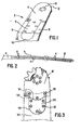
- Figures 1 and 2 illustrate in perspective and side elevation views respectively (in exaggerated form for illustrative purposes) a bent bar nose and cutter bar assembly 2 of the original Scott-Jackson construction as disclosed and claimed in U.S. Patent No. 3,762,047.
- a chain saw is used in the . field in felling trees and cutting wood, it has been found that bending of the cutter bar is a relatively frequently occurring problem.
- the cutter bar can become bent either through hard or rough use, or in a tree falling accident, or when a tree is being felled by cutting a kerf through the tree, and the tree accidentally sets back on the bar, or bar nose.
- Figure 2 illustrates in side elevation view (in somewhat exaggerated manner for illustrative purposes) a bent bar-nose assembly 2 of the Scott-Jackson design wherein two face plates 4 with respective extension connector sections 6 extend into receptacles built into the basic cutter bar 8.
- a spacer plate 14 is positioned and sandwiched between the two connector extensions 6.
- the concept is embodied in a combination of a solid web at the forward nose end of the bar, and a special spacer plate mounted in the interior of the bar and nose.
- the spacer plate is designed to provide a first point of variation in strength at its curved sprocket facing side and a second point of variation in strength at the lower curved edge at the end facing the bar.
- the sprocket facing curve corresponds with the curve of the ends of the sprocket teeth. This lower curve matches a similar curved edge at the nose facing edge of the solid web.
- the concept of two points of variation in strength provides a graduated bending pattern whereby the first point of variation in strength bends on the application of an initial bending force which is sufficient to bend the assembly. If a greater bending force is exerted on the sprocket nose assembly, that is, one which is sufficiently great that it will not be absorbed initially by bending at the first point of variation in strength, then bending or distortion of the bar and nose assembly takes place at the second point of variation in strength as well.
- the overall bar yields at two locations and can be bent much farther than is usually possible before pinching of the sprocket by binding, or bending of the laminating face plates takes place Any permanent bends which occur in the areas of the calculated points of variation in strength (the curved edge -zone) can be corrected in an inexpensive straightening operation, thereby permitting continued use of the bar and nose assembly.
- the commensurate curves of the web and spacer plate at the second point of variation in strength are designed to carefully balance operational strength of the chain saw with calculated yield strength when the bar-nose assembly is subjected to excessive bending action.
- a larger radius curve results in an unduly and unacceptably weak bar-nose section.
- a smaller radius curve tends to have too much inherent strength and this tends to shift the likely point of bending in the direction of the nose and sprocket, thus thereby aggravating the sprocket pinching problem.
- the length of the pair of matching curves is sufficient to resist normal twisting and bending moments exerted on the bar-nose assembly under operating conditions.
- the novel saw bar-nose construction is also directed to alleviating a secondary problem.
- the bar extensions are joined by a solid web under the nose plate extensions.
- the maximum web area is designed to provide sufficient overall strength to the bar-nose assembly as well as detering potential extension spreading forces.
- the new bar-nose assembly also provides for a rearrangement of rivets which hold the nose in permanent position.
- the total number of rivet openings has been reduced, thereby reducing manufacturing costs.
- the rivets have been respaced to reduce concentrations of stresses or forces in localized areas and thereby avoid cracking and/or failure of the bar or nose due to stress fatigue.
- the distribution of rivets and rivet openings with resultant even stress distribution provides for a strong nose and bar assembly.
- Other pitches of chain and sprockets use the same concept and general design to provide maximum strength and flexibility in manufacturing of the bar and nose components.
- Figure 3 represents a front elevation view (partially cut-away) of the bar-nose cutter bar assembly.
- Figure 3 discloses the fundamental components of the novel bar-nose assembly of the invention.
- the nose is formed of a pair of matching facing side plates 16 which, as shown in Figure 3, and by means of the cut-away portion, are positioned in front of and behind sprocket 18, thereby sandwiching or laminating the sprocket 18 between them.
- the bearing centre 20, and bearing rollers 22, which make up the sprocket combination can also be seen in Figure 3.
- the sprocket 18, bearing centre 20, and bearing rollers 22, are held in place by six rivets 24.
- the side plate 16 is constructed so that it has a connector extension 28, which is of a design similar to the nose plate design shown in the original Scott-Jackson design in U.S. Patent No. 3,762,047.
- the connector extension 28 is shaped so that it is congruent with and fits in the receptacle 48 which is machined in the forward end of cutter bar 34.
- the connector 28 is secured to the cutter bar 34 by means of five rivets 32. These rivets are disposed so as to spread the stresses and bending forces evenly throughout the connector, extension 28 and the cutter bar 34.
- a centre plate 26 is located behind side plate 16. Centre plate 26 is held in place by means of three centre plate rivets 30. Centre plate 26 is designed so that it has a generally overall crescent shape, with a lower curved edge, which corresponds with and lies adjacent to an upper curved edge of a portion of the cutter bar. This construction will be discussed in further detail below.
- the three centre plate rivets 30 are spatially distributed so that they spread stresses evenly throughout the centre plate 26 and the side plate 16.
- Figure 4 illustrates a front elevation view of the face plate 16 with spaced rivet holes punched, drilled or bored therein.
- the face plate 16 is shaped to have a curved nose covering the sprocket, except for protruding sprocket teeth, and a curved connector extension 28 on one side thereof opposite the curved nose of the side plate 16.
- the side plate 16 has punched, bored or drilled therein a circular array of sprocket rivet holes 36.
- Three spatially arranged centre plate rivet holes 38 are punched, drilled or bored in the central area of the side plate 16.
- a spatially arranged group of five extension rivet holes 14 is punched, drilled or bored in the connector extension 28.
- Figure 5 illustrates a front elevation view of the centre plate 26.
- Three centre plate rivet holes 38 are punched, drilled or bored in the centre plate 26. The position of these rivet holes 38 corresponds with the three rivet holes 38 in the side plate 16, as discussed previously in relation to Figure 4.
- the bottom or lower edge 54 of the centre plate 26 is convex curved in a semi-circular pattern.
- Figures 6 and 7 illustrate front elevation and side section views of the sprocket 18, with bearing centre hole 42.
- the design of the sprocket 18 and centre bearing hole 42 is basically the same as the design of the sprocket illustrated in the original Scott-Jackson design disclosed and claimed in U.S. Patent No. 3,762,047.
- Figures 8 and 9 illustrate in front elevation and side section views respectively the construction of the bearing centre 20.
- the bearing centre 20 has punched, bored or drilled therein a circular arrangement of six bearing centre rivet holes 44. The spacing and position of these rivet holes 44 corresponds with the corresponding rivet holes in side plate 16, as discussed previously in association with Figure 4.
- Figure 10 illustrates in front elevation view the construction of the cutter bar 34.
- the cutter bar 34 has formed therein on each side at the forward end, a pair of connector extension receptacles 48, which are machined to be congruent with and fit snugly with the shape of the extensions of the respective pair of side plate connector extensions 28, illustrated in Figure 4.
- the matching receptacles 48 machined in the forward end of the bar are not cut completely through the thickness of the bar.
- a web 46 of thickness equal to that of centre plate 26, remains in the mid-section of the cutter bar 34, when the pair of receptacles 48 are milled from each side of the cutter bar 34.
- Punched, drilled or bored in spatial arrangement in the web 46 are five extension-web rivet holes 50 which correspond in size and location with the five extension rivet holes 40 which are machined in the respective pair of matching side plates 16.
- An important feature of the construction of the cutter bar 34, as illustrated in Figure 10, is the curved centre plate facing edge 52, shown at the top side of the cutter bar 34.
- the radius of the facing edge 52 has the same pivot point as the radius of curvature of the curved web facing edge 54 (see Figure 5).
- the radius of curvature selected for the curved centre plate facing edge 52 on cutter bar 34, and the curved web facing edge 54 on the centre plate 26, is important to the proper functioning of the invention. As can be seen in Figure 3, when the cutter bar-nose combination is assembled, curved edge 52 and curved edge 54 respectively are spaced slightly apart. The purpose of the matching curved edges 52 and 54 is to provide at this location within the interior of the cutter bar assembly a second calculated point of variation in strength.
- the curvatures of the facing edges 52 and 54 are carefully selected to strike a compromise balance between ensuring sufficient overall strength of the cutter bar assembly and providing a calculated location of strength variation which manifests itself if and when a strong distorting and potentially damaging binding or bending action is exerted on the cutter bar assembly.
- a curve of large radius that is, a shallow curve of the corresponding facing edges 52 and 54
- a curve of small radius that is, a tight curve
- the cutter bar assembly is encouraged to bend at a location closer to the sprocket. This nullifies or offsets the advantage and effect of the second calculated point of strength.
- a first calculated point of variation in strength is located at the curved sprocket facing edge 53, as described previously (see Figure 5).
- a second point of variation in strength is located between edges 52 and 54. Consequently, when an excessive binding or bending force is applied to the bar-nose assembly, such as might occur in use in the field, the cutter bar-nose assembly is encouraged first to bend or distort at the location between the facing edges 52 and 54. Since the second point of calculated strength variation is removed from the sprocket 18, the bar-nose assembly, by means of the matching curved edges 52 and 54, is encouraged to bend at a point removed from the sprocket 18 when the bending forces are severe. The result is a segregated gradual bending profile rather than a sharp bend at a single location.
- the utilization of the spacer web 46 in the cutter bar 34 is also an important feature of the invention.
- the web 46 is advantageous in that it acts as a retaining means to prevent the extensions of the cutter bar 34 on either side of the web 46 to spread apart due to stress, as can occur when the cutter bar-nose assembly is subjected to prolonged heavy use or abuse.
- U.S. Patent No. 3,762,047 no spacer web 46 is present.
- the extensions of the cutter bar on either side of the spacer 65 to spread slightly when the cutter bar-nose assembly.is subjected to rough handling, tough use or longstanding use. Indeed, in rare instances, one or more of the extensions may become permanently bent or even broken. In any event, when spreading of the extensions takes place, the chain saw guide bar must be replaced.
- Figure 11 illustrates in exploded perspective view, the components which make up the cutter bar-nose assembly.
- a pair of matching side plates 16 cooperate to sandwich or laminate the sprocket 18, bearing centre 20 and bearing rollers 22 between them.
- the centre plate 26 is sandwiched or laminated between the two matching side plates 16.
- the respective connector extensions 28 of each side plate 16 fit within the respective receptacles 48 machined in both sides of the cutter bar 34.
- the thicknesses of the bearing centre 20, centre plate 26, and spacer web 46 are basically equal to provide a close fitting strong construction.
- the thickness of the sprocket 18, however, is slightly less than the thickness of the bearing centre.20, to enable the sprocket 18 to rotate freely around the bearing centre 20 in combination with the bearing rollers 22 and free of the pair of side plates 16.
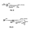
- a Pinch Test as described below and illustrated in Figure 12 was conducted on the chain saw bar which is the subject of this patent application, the Scott-Jackson design discussed previously and several other bars available in the marketplace to determine the amount of force that is necessary to create restrictive sprocket nose rotation in such bars.
- the replaceable sprocket nose in each case was held in a vice, as illustrated in Figure 12 and a force was applied transversely at 24 inches from the clamping point.
- the sprocket nose was continually rotated as the force was steadily increased. When the nose rotation became restrictive, the amount of force was noted as well as the deflection of the bar at 1 inch from the clamping point.
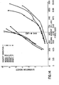
- the Bending Test was used to simulate a sprocket nose being pinched in a free cut (kerf) and as a result the operator then uses a bending force in an attempt to free the saw. This action can cause severe bending stress on the pinched section of the bar and possible plastic deformation of the bar.
- the Bend Test simulates a particular abuse condition in the field.
- a typical example would be a logger using a conventional chain saw with a 32 inch bar. While cutting, the nose becomes pinched and the logger cannot free it. The logger leaves the saw to get an axe. He leaves the saw hanging by the pinched nose.
- the saw and bar assembly which normally weighs about 20 pounds, would cause a moment on the bar of about 640 in./lbs. (This is taking for granted that the person lets the saw down gradually without allowing it to oscillate, which would aggravate the situation.)
- the bars identified as Models C, D and E would deform substantially causing permanent nose damage.
- the design of the instant invention would deform a minimal amount, thereby causing no serious nose damage. No bending back into shape is required.
Landscapes
- Life Sciences & Earth Sciences (AREA)
- Engineering & Computer Science (AREA)
- Mechanical Engineering (AREA)
- Wood Science & Technology (AREA)
- Forests & Forestry (AREA)
- Sawing (AREA)
- Processing Of Stones Or Stones Resemblance Materials (AREA)
- Manufacturing And Processing Devices For Dough (AREA)
Applications Claiming Priority (2)
| Application Number | Priority Date | Filing Date | Title |
|---|---|---|---|
| CA479885 | 1985-04-23 | ||
| CA479885 | 1985-04-23 |
Publications (1)
| Publication Number | Publication Date |
|---|---|
| EP0202731A1 true EP0202731A1 (fr) | 1986-11-26 |
Family
ID=4130341
Family Applications (1)
| Application Number | Title | Priority Date | Filing Date |
|---|---|---|---|
| EP86301271A Ceased EP0202731A1 (fr) | 1985-04-23 | 1986-02-21 | Scie à chaîne |
Country Status (3)
| Country | Link |
|---|---|
| US (1) | US4722141A (fr) |
| EP (1) | EP0202731A1 (fr) |
| JP (1) | JPS61244501A (fr) |
Families Citing this family (19)
| Publication number | Priority date | Publication date | Assignee | Title |
|---|---|---|---|---|
| USD321819S (en) | 1987-09-02 | 1991-11-26 | Sugihara Rinki Co., Ltd. | Guide bar for chain saw |
| US4813135A (en) * | 1987-10-13 | 1989-03-21 | Daniel Kuwica | Roller nose bar |
| ES2038007T3 (es) * | 1989-03-11 | 1993-07-01 | Heinrich Kesper | Barra de guia para sierras de cadena motorizadas. |
| US5052109A (en) * | 1990-10-26 | 1991-10-01 | Blount, Inc. | Repairable guide bar for tree harvesters |
| US5092044A (en) * | 1991-04-18 | 1992-03-03 | Blount, Inc. | Fluid injecting nose sprocket for a chain saw guide bar |
| SE9103267L (sv) * | 1991-11-06 | 1993-05-07 | Sandvik Ab | Saagsvaerd foer kedjesaagar |
| CA2109263A1 (fr) * | 1992-10-28 | 1994-04-29 | Thomas Beerens | Guide de chaine muni d'un galet, pour scie a chaine |
| SE9303015D0 (sv) * | 1993-09-16 | 1993-09-16 | Sandvik Ab | kedjesågsvärd med lång livslängd |
| US5471751A (en) * | 1993-12-15 | 1995-12-05 | Sandvik Windsor Corporation | Low friction guide bar for a chain saw |
| US5596811A (en) * | 1995-04-25 | 1997-01-28 | Sandvik Ab | Chainsaw guide bar |
| US6964101B2 (en) * | 2002-12-12 | 2005-11-15 | Blount, Inc. | Lightweight guide bar for chainsaw |
| US20050178010A1 (en) * | 2004-01-23 | 2005-08-18 | Alex Petrenko | Chainsaw tool |
| US9125391B2 (en) | 2012-03-26 | 2015-09-08 | Raymond W. Egan, Jr. | Swiveling tip for a fishing rod |
| JP1518722S (fr) * | 2014-07-16 | 2018-02-26 | ||
| USD839705S1 (en) * | 2017-09-11 | 2019-02-05 | Blount, Inc. | Sprocket nose |
| USD845099S1 (en) * | 2017-09-11 | 2019-04-09 | Blount, Inc. | Sprocket nose |
| USD845731S1 (en) * | 2017-09-11 | 2019-04-16 | Blount, Inc. | Chainsaw guide bar body |
| USD839706S1 (en) * | 2017-09-11 | 2019-02-05 | Blount, Inc. | Chainsaw guide bar body |
| JP2021107097A (ja) * | 2019-12-27 | 2021-07-29 | 末廣精工株式会社 | チェーンソーのガイドバー |
Citations (5)
| Publication number | Priority date | Publication date | Assignee | Title |
|---|---|---|---|---|
| US3955279A (en) * | 1975-05-19 | 1976-05-11 | Omark Industries, Inc. | Guide bar for chain saw having a replaceable nose portion |
| US3987544A (en) * | 1976-04-30 | 1976-10-26 | Omark Industries, Inc. | Chain saw guide bar with detachable nose |
| US4021913A (en) * | 1976-01-22 | 1977-05-10 | Outboard Marine Corporation | Sprocket nose chain saw |
| US4060895A (en) * | 1976-11-15 | 1977-12-06 | Omark Industries, Inc. | Non-symmetrical bar with reversible body portion |
| WO1982001846A1 (fr) * | 1980-11-24 | 1982-06-10 | James E Halverson | Barre de scie articulee avec tension automatique |
Family Cites Families (4)
| Publication number | Priority date | Publication date | Assignee | Title |
|---|---|---|---|---|
| US2316997A (en) * | 1940-08-29 | 1943-04-20 | Reed Prentice Corp | Tensioning means for chain saws |
| US3762047A (en) * | 1972-02-07 | 1973-10-02 | Windsor Mach Co | Cutter bar with speed tip |
| CA1123713A (fr) * | 1979-08-31 | 1982-05-18 | Windsor Machine Company Limited | Accouplement de barreaux |
| JPS5915502U (ja) * | 1982-07-21 | 1984-01-30 | 末広精工株式会社 | チエンソ−用チエン案内板 |
-
1985
- 1985-09-03 US US06/772,142 patent/US4722141A/en not_active Expired - Fee Related
-
1986
- 1986-02-21 EP EP86301271A patent/EP0202731A1/fr not_active Ceased
- 1986-04-21 JP JP61093189A patent/JPS61244501A/ja active Pending
Patent Citations (5)
| Publication number | Priority date | Publication date | Assignee | Title |
|---|---|---|---|---|
| US3955279A (en) * | 1975-05-19 | 1976-05-11 | Omark Industries, Inc. | Guide bar for chain saw having a replaceable nose portion |
| US4021913A (en) * | 1976-01-22 | 1977-05-10 | Outboard Marine Corporation | Sprocket nose chain saw |
| US3987544A (en) * | 1976-04-30 | 1976-10-26 | Omark Industries, Inc. | Chain saw guide bar with detachable nose |
| US4060895A (en) * | 1976-11-15 | 1977-12-06 | Omark Industries, Inc. | Non-symmetrical bar with reversible body portion |
| WO1982001846A1 (fr) * | 1980-11-24 | 1982-06-10 | James E Halverson | Barre de scie articulee avec tension automatique |
Also Published As
| Publication number | Publication date |
|---|---|
| JPS61244501A (ja) | 1986-10-30 |
| US4722141A (en) | 1988-02-02 |
Similar Documents
| Publication | Publication Date | Title |
|---|---|---|
| EP0202731A1 (fr) | Scie à chaîne | |
| US5628116A (en) | Bearing usable for scissors and scissors using the same | |
| AU599257B2 (en) | Cutter, in particular for slat, especially of venetion blind | |
| US2736352A (en) | Saw tooth assembly | |
| US5063671A (en) | Kitchen shears with hiding spring | |
| US4316315A (en) | Pliers | |
| EP2943320B1 (fr) | Pignon et système d'orientation d'un maillon de chaîne de scie sur un pignon | |
| EP0239659A1 (fr) | Plaquette nasale souple pour monter dans une monture de lunettes | |
| US3949475A (en) | Chain saw guide bar | |
| GB2117318A (en) | Cutting link for a chain cutter | |
| US3815229A (en) | Hedge trimmer attachment for a chain saw | |
| US2903033A (en) | Closure devices | |
| US2749950A (en) | Insert tooth for power saw chain | |
| US4465113A (en) | Roller maul | |
| US4506576A (en) | Mat board cutter with knife blade securing safety pin | |
| DE3412977A1 (de) | Elastische befestigung fuer den stangenfoermigen zahn einer trennsaege | |
| US6341545B1 (en) | Jaw assembly for pivotal handle tool with opposing jaw elements | |
| US4259783A (en) | Bar jointing | |
| US4211136A (en) | Cutter assembly for saw chain | |
| US5105704A (en) | Adjustable saw blade fastener | |
| US3698168A (en) | Blade connecting means | |
| US4745827A (en) | File guide for saw chain cutter teeth | |
| US4765062A (en) | Arrangement in a chain saw | |
| US2897857A (en) | Saw chain cutters with thin cutting portion and thick base | |
| US3476160A (en) | Twin bar chain saw bar |
Legal Events
| Date | Code | Title | Description |
|---|---|---|---|
| PUAI | Public reference made under article 153(3) epc to a published international application that has entered the european phase |
Free format text: ORIGINAL CODE: 0009012 |
|
| AK | Designated contracting states |
Kind code of ref document: A1 Designated state(s): AT BE CH DE FR GB IT LI LU NL SE |
|
| 17P | Request for examination filed |
Effective date: 19870223 |
|
| 17Q | First examination report despatched |
Effective date: 19870820 |
|
| STAA | Information on the status of an ep patent application or granted ep patent |
Free format text: STATUS: THE APPLICATION HAS BEEN REFUSED |
|
| 18R | Application refused |
Effective date: 19890814 |
|
| RIN1 | Information on inventor provided before grant (corrected) |
Inventor name: SCOTT-JACKSON, DENNIS G. Inventor name: LIM, HUI CHANG |