EP0202726A1 - Wellhead sealing assembly - Google Patents
Wellhead sealing assembly Download PDFInfo
- Publication number
- EP0202726A1 EP0202726A1 EP86300805A EP86300805A EP0202726A1 EP 0202726 A1 EP0202726 A1 EP 0202726A1 EP 86300805 A EP86300805 A EP 86300805A EP 86300805 A EP86300805 A EP 86300805A EP 0202726 A1 EP0202726 A1 EP 0202726A1
- Authority
- EP
- European Patent Office
- Prior art keywords
- ring
- energizing
- shoulder
- seal
- rings
- Prior art date
- Legal status (The legal status is an assumption and is not a legal conclusion. Google has not performed a legal analysis and makes no representation as to the accuracy of the status listed.)
- Granted
Links
- 238000007789 sealing Methods 0.000 title claims abstract description 36
- 239000002184 metal Substances 0.000 claims 3
- 241000191291 Abies alba Species 0.000 description 2
- 230000000712 assembly Effects 0.000 description 1
- 238000000429 assembly Methods 0.000 description 1
- 229920001971 elastomer Polymers 0.000 description 1
- 239000000806 elastomer Substances 0.000 description 1
Images


Classifications
-
- F—MECHANICAL ENGINEERING; LIGHTING; HEATING; WEAPONS; BLASTING
- F16—ENGINEERING ELEMENTS AND UNITS; GENERAL MEASURES FOR PRODUCING AND MAINTAINING EFFECTIVE FUNCTIONING OF MACHINES OR INSTALLATIONS; THERMAL INSULATION IN GENERAL
- F16J—PISTONS; CYLINDERS; SEALINGS
- F16J15/00—Sealings
- F16J15/02—Sealings between relatively-stationary surfaces
- F16J15/021—Sealings between relatively-stationary surfaces with elastic packing
- F16J15/028—Sealings between relatively-stationary surfaces with elastic packing the packing being mechanically expanded against the sealing surface
-
- E—FIXED CONSTRUCTIONS
- E21—EARTH OR ROCK DRILLING; MINING
- E21B—EARTH OR ROCK DRILLING; OBTAINING OIL, GAS, WATER, SOLUBLE OR MELTABLE MATERIALS OR A SLURRY OF MINERALS FROM WELLS
- E21B33/00—Sealing or packing boreholes or wells
- E21B33/02—Surface sealing or packing
- E21B33/03—Well heads; Setting-up thereof
- E21B33/04—Casing heads; Suspending casings or tubings in well heads
-
- E—FIXED CONSTRUCTIONS
- E21—EARTH OR ROCK DRILLING; MINING
- E21B—EARTH OR ROCK DRILLING; OBTAINING OIL, GAS, WATER, SOLUBLE OR MELTABLE MATERIALS OR A SLURRY OF MINERALS FROM WELLS
- E21B2200/00—Special features related to earth drilling for obtaining oil, gas or water
- E21B2200/01—Sealings characterised by their shape
Definitions
- the sealing assembly In one example of prior art a wellhead sealing assembly designed for sealing in the annulus between the first and second casings at the wellhead of a geothermal well, the sealing assembly includes a first ring with inner and outer seals mounted thereon and separate energizing rings which are actuated by screws extending vertically through a flange spanning the annulus above the sealing assembly.
- This structure is shown in U.S. Patent No. 4,299,395.
- U.S. Patent No. 2,768,841 Another example of a wellhead sealing assembly is shown in U.S. Patent No. 2,768,841.
- the sealing assembly in this structure includes a base ring with a sealing ring above it and a top ring which has a tapered upper-outer surface engaged by tiedown screws extending through the wellhead housing in a radial direction.
- the W.L. Todd et al Patent No. 3,494,638 discloses a sealing assembly energized by radially extending tiedown screws and the seal ring includes an upper ring, a lower ring and a seal ring between them with screws initially loading the seal rings.
- a similar structure is shown in the J.W. Thatch Patent No. 2,617,485.
- the present invention relates to an improved wellhead assembly structure with an improved sealing assembly included therein.
- the improved structure includes the wellhead housing, a well casing suspended within the housing with an annular space therebetween in which the improved sealing assembly is mounted.
- the sealing assembly includes a base ring with inner and outer shoulders and a groove between the shoulders, an inner seal ring, an outer seal ring, a first energizing ring for energizing the inner seal ring and having lugs extending outwardly with the upper outer surfaces of the lugs being tapered downwardly and radially outward, a second energizing ring for energizing the outer seal ring and having upwardly opening slots for receiving the lugs of the first energizing ring and having upper outer shoulders which taper downwardly and radially outward, the two energizing rings are independently urged to compress their respective seal rings by the inward movement of the radially extending tiedown screws which are all positioned at the same level extending radially through
- An object of the present invention is to provide an improved wellhead assembly with an improved sealing assembly in the annulus between the wellhead housing and the casing which includes separate inner and outer seal rings which can be separately energized by radially extending tiedown screws.
- Another object is to provide an improved wellhead annulus sealing assembly including separately energizable inner and outer seal rings which provides sealing under extremes of cold and heat.
- a further object is to provide an improved wellhead annulus sealing assembly which provides adequate sealing against a wide range of casing diameters.
- Still another object is to provide an improved wellhead annulus sealing assembly which is a unitary assembly with separately energizable inner and outer seal rings.
- An additional object is to provide an improved wellhead annulus sealing assembly, with separately energizable inner and outer seal rings, which remains in place and energized when the Christmas tree has been removed.
- Wellhead assembly 10 as shown in FIGURE 1 includes housing 12 having upper flange 14 to which other structure, such as a Christmas tree (not shown), may be connected as desired.
- Housing 12 is tubular and includes upwardly facing lower tapered shoulder 16 which supports hanger ring 18 which supports casing 20 in its position extending through housing 12.
- Housing 12 also includes angled shoulder 22 above shoulder 16. Shoulder 22 is sized to support seal structure 24 as shown.
- Seal structure 24 includes annular seal assembly 26 and tiedown screws 28a and 28b extending radially through housing flange 14.
- Annular seal assembly 26 includes base ring 30, inner seal ring 32, outer seal ring 34, outer energizing ring 36, inner energizing ring 38 and retaining screws 39.
- Base ring 30 includes upwardly facing inner shoulder 42, upwardly facing outer shoulder 44, annular groove or recess 46 between shoulders 42 and 44 and downwardly facing outer tapered surface 45.
- Seal structure 24 When seal structure 24 is positioned in housing 12, it is supported by engagement of surface 45 on shoulder 22 in housing 12.
- Outer seal ring 34 is positioned on shoulder 44 and is engaged by outer energizing ring 36.
- Inner seal ring 32 is positioned on shoulder 42 and is engaged by inner energizing ring 38.
- Inner energizing ring 38 includes depending annular projection 48 which is positioned between seal rings 32 and 34 and extends into recess 46.
- inner energizing ring 38 also includes outwardly extending lugs 50 with their upper outer surfaces 52 tapered downwardly and outwardly.
- Outer energizing ring 36 is positioned around projection 48 of ring 38 and includes upwardly facing slots 54 in which lugs 50 of ring 38 are received and upper surfaces 56 which taper downwardly and outwardly.
- the interengagement of lugs 50 in slots 54 positions the upper surfaces of energizing rings 36 and 38 on approximately the same level so that they are in proper position to be engaged by tiedown screws 28b and 28a.
- the positioning of lugs 50 in slots 54 and the engagement of screws 28b and 28a with energizing rings 36 and 38 is best seen in FIGURE 2.
- the upper surface of energizing ring 38 has a plurality of tapped holes 58 to receive lifting lugs (not shown) for placing and removing sealing assembly 26.
- the screws 28 are designated 28a for those screws which engage and energize inner energizing ring 38 and 28b for those screws which engage and energize outer energizing ring 36.
- Seal assembly 26 is shown in FIGURE 3 in its assembled position without any forces being exerted on seal rings 32 and 34 which would compress the rings into their set positions.
- Seal assembly 26 as shown in FIGURE 4 has been moved to its set position with seal rings 32 and 34 being compressed axially to cause them to expand radially into sealing engagement with the surfaces against which they are to seal.
- Retainer screws 39 as shown in FIGURE 3, keep the individual components of seal assembly 26 together so they can be installed and removed as one preassembled unit.
Landscapes
- Engineering & Computer Science (AREA)
- Geology (AREA)
- General Engineering & Computer Science (AREA)
- Mining & Mineral Resources (AREA)
- Life Sciences & Earth Sciences (AREA)
- Geochemistry & Mineralogy (AREA)
- Fluid Mechanics (AREA)
- Environmental & Geological Engineering (AREA)
- Physics & Mathematics (AREA)
- General Life Sciences & Earth Sciences (AREA)
- Mechanical Engineering (AREA)
- Gasket Seals (AREA)
- Electroluminescent Light Sources (AREA)
- Liquid Crystal (AREA)
- Glass Compositions (AREA)
- Supporting Of Heads In Record-Carrier Devices (AREA)
- Paper (AREA)
- Seal Device For Vehicle (AREA)
- Encapsulation Of And Coatings For Semiconductor Or Solid State Devices (AREA)
- Road Signs Or Road Markings (AREA)
- Excavating Of Shafts Or Tunnels (AREA)
Abstract
Description
- Difficulties have been encountered in prior wellhead sealing assemblies in sealing between the exterior of the casing and the interior of the wellhead housing since the exterior of the casing may vary considerably in its dimensions. Additionally, extremely cold temperatures have made sealing with elastomers difficult because they contract very measurably in cold environments.
- In one example of prior art a wellhead sealing assembly designed for sealing in the annulus between the first and second casings at the wellhead of a geothermal well, the sealing assembly includes a first ring with inner and outer seals mounted thereon and separate energizing rings which are actuated by screws extending vertically through a flange spanning the annulus above the sealing assembly. This structure is shown in U.S. Patent No. 4,299,395.
- Another example of a wellhead sealing assembly is shown in U.S. Patent No. 2,768,841. The sealing assembly in this structure includes a base ring with a sealing ring above it and a top ring which has a tapered upper-outer surface engaged by tiedown screws extending through the wellhead housing in a radial direction.
- The W.L. Todd et al Patent No. 3,494,638 discloses a sealing assembly energized by radially extending tiedown screws and the seal ring includes an upper ring, a lower ring and a seal ring between them with screws initially loading the seal rings. A similar structure is shown in the J.W. Thatch Patent No. 2,617,485.
- The present invention relates to an improved wellhead assembly structure with an improved sealing assembly included therein. The improved structure includes the wellhead housing, a well casing suspended within the housing with an annular space therebetween in which the improved sealing assembly is mounted. The sealing assembly includes a base ring with inner and outer shoulders and a groove between the shoulders, an inner seal ring, an outer seal ring, a first energizing ring for energizing the inner seal ring and having lugs extending outwardly with the upper outer surfaces of the lugs being tapered downwardly and radially outward, a second energizing ring for energizing the outer seal ring and having upwardly opening slots for receiving the lugs of the first energizing ring and having upper outer shoulders which taper downwardly and radially outward, the two energizing rings are independently urged to compress their respective seal rings by the inward movement of the radially extending tiedown screws which are all positioned at the same level extending radially through the wellhead housing.
- An object of the present invention is to provide an improved wellhead assembly with an improved sealing assembly in the annulus between the wellhead housing and the casing which includes separate inner and outer seal rings which can be separately energized by radially extending tiedown screws.
- Another object is to provide an improved wellhead annulus sealing assembly including separately energizable inner and outer seal rings which provides sealing under extremes of cold and heat.
- A further object is to provide an improved wellhead annulus sealing assembly which provides adequate sealing against a wide range of casing diameters.
- Still another object is to provide an improved wellhead annulus sealing assembly which is a unitary assembly with separately energizable inner and outer seal rings.
- An additional object is to provide an improved wellhead annulus sealing assembly, with separately energizable inner and outer seal rings, which remains in place and energized when the Christmas tree has been removed.
- These and other objects and advantages of the present invention are hereinafter set forth and explained with reference to the drawings wherein:
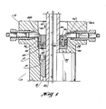
- FIGURE 1 is an elevation view of the improved wellhead structure of the present invention with the central portion omitted, with the left half thereof shown in section to illustrate the outer seal energizing structure and with the right half portions in section to illustrate the inner seal energizing structure.
- FIGURE 2 is a plan view of the sealing assembly showing the tiedown screws schematically thereon to illustrate the operation of each set of screws with the energizing rings.
- FIGURE 3 is a sectional view taken along line 3-3 in FIGURE 2 of the sealing assembly in its assembled position before it is set.
- FIGURE 4 is similar section view of the sealing assembly but showing it in its set position.
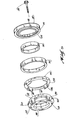
- FIGURE 5 is an exploded view of the components of the sealing assembly.
- Wellhead assembly 10 as shown in FIGURE 1 includes
housing 12 having upper flange 14 to which other structure, such as a Christmas tree (not shown), may be connected as desired.Housing 12 is tubular and includes upwardly facing lowertapered shoulder 16 which supports hanger ring 18 which supportscasing 20 in its position extending throughhousing 12.Housing 12 also includesangled shoulder 22 aboveshoulder 16.Shoulder 22 is sized to supportseal structure 24 as shown. -
Seal structure 24 includesannular seal assembly 26 andtiedown screws 28a and 28b extending radially through housing flange 14.Annular seal assembly 26 includesbase ring 30,inner seal ring 32,outer seal ring 34, outerenergizing ring 36, innerenergizing ring 38 and retainingscrews 39.Base ring 30 includes upwardly facinginner shoulder 42, upwardly facingouter shoulder 44, annular groove orrecess 46 betweenshoulders tapered surface 45. Whenseal structure 24 is positioned inhousing 12, it is supported by engagement ofsurface 45 onshoulder 22 inhousing 12.Outer seal ring 34 is positioned onshoulder 44 and is engaged by outer energizingring 36.Inner seal ring 32 is positioned onshoulder 42 and is engaged by innerenergizing ring 38. Innerenergizing ring 38 includes dependingannular projection 48 which is positioned betweenseal rings recess 46. - As shown in FIGURES 2 and 5, inner
energizing ring 38 also includes outwardly extendinglugs 50 with their upperouter surfaces 52 tapered downwardly and outwardly. Outer energizingring 36 is positioned aroundprojection 48 ofring 38 and includes upwardly facingslots 54 in whichlugs 50 ofring 38 are received andupper surfaces 56 which taper downwardly and outwardly. The interengagement oflugs 50 inslots 54 positions the upper surfaces of energizingrings tiedown screws 28b and 28a. The positioning oflugs 50 inslots 54 and the engagement ofscrews 28b and 28a withenergizing rings ring 38 has a plurality of tappedholes 58 to receive lifting lugs (not shown) for placing and removingsealing assembly 26. In this drawing the screws 28 are designated 28a for those screws which engage and energize inner energizingring 38 and 28b for those screws which engage and energize outer energizingring 36. -
Seal assembly 26 is shown in FIGURE 3 in its assembled position without any forces being exerted onseal rings Seal assembly 26 as shown in FIGURE 4 has been moved to its set position withseal rings -
Retainer screws 39, as shown in FIGURE 3, keep the individual components ofseal assembly 26 together so they can be installed and removed as one preassembled unit.
Claims (7)
Priority Applications (1)
| Application Number | Priority Date | Filing Date | Title |
|---|---|---|---|
| AT86300805T ATE75525T1 (en) | 1985-05-16 | 1986-02-06 | WELL HEAD SEALING ASSEMBLY. |
Applications Claiming Priority (2)
| Application Number | Priority Date | Filing Date | Title |
|---|---|---|---|
| US06/734,544 US4645214A (en) | 1985-05-16 | 1985-05-16 | Wellhead sealing assembly |
| US734544 | 1985-05-16 |
Publications (2)
| Publication Number | Publication Date |
|---|---|
| EP0202726A1 true EP0202726A1 (en) | 1986-11-26 |
| EP0202726B1 EP0202726B1 (en) | 1992-04-29 |
Family
ID=24952121
Family Applications (1)
| Application Number | Title | Priority Date | Filing Date |
|---|---|---|---|
| EP86300805A Expired - Lifetime EP0202726B1 (en) | 1985-05-16 | 1986-02-06 | Wellhead sealing assembly |
Country Status (8)
| Country | Link |
|---|---|
| US (1) | US4645214A (en) |
| EP (1) | EP0202726B1 (en) |
| JP (1) | JPS61266795A (en) |
| AT (1) | ATE75525T1 (en) |
| CA (1) | CA1258621A (en) |
| DE (1) | DE3685055D1 (en) |
| NO (1) | NO170898C (en) |
| SG (1) | SG109892G (en) |
Cited By (2)
| Publication number | Priority date | Publication date | Assignee | Title |
|---|---|---|---|---|
| WO2020225542A1 (en) * | 2019-05-03 | 2020-11-12 | Oil States Industries (Uk) Limited | Apparatus and method relating to managed pressure drilling |
| US11828111B2 (en) | 2018-11-06 | 2023-11-28 | Oil States Industries (Uk) Limited | Apparatus and method relating to managed pressure drilling |
Families Citing this family (11)
| Publication number | Priority date | Publication date | Assignee | Title |
|---|---|---|---|---|
| US4848777A (en) * | 1987-09-18 | 1989-07-18 | Fmc Corporation | Pressure energized/pressure intensified casing seal |
| US5071140A (en) * | 1990-01-02 | 1991-12-10 | Federico Quevedo Del Rio | Self-pressurized gasket seal |
| US5114158A (en) * | 1990-11-19 | 1992-05-19 | Le Tri C | Packing assembly for oilfield equipment and method |
| US5148865A (en) * | 1991-04-08 | 1992-09-22 | Reed Lehman T | Multi-conversion wellhead assembly |
| RU2217574C2 (en) * | 2001-12-13 | 2003-11-27 | Закрытое акционерное общество "Газтехнология" | Sealing unit for mouth |
| CN1858397B (en) * | 2006-06-09 | 2010-05-12 | 徐元信 | Diameter adjustable blowout preventer for oil field |
| US8887829B2 (en) * | 2006-11-20 | 2014-11-18 | Hubbell Incorporated | Static/dynamic shaft seal |
| US10287839B2 (en) | 2015-05-04 | 2019-05-14 | Cameron International Corporation | Wellhead tiedown system |
| USD992993S1 (en) | 2020-09-08 | 2023-07-25 | Ripen Pull, LLC | Lock pin puller |
| US11952857B2 (en) | 2020-11-03 | 2024-04-09 | Ripen Pull, LLC | Locking pin tool for use with a locking pin of a wellhead |
| CN115143653B (en) * | 2022-06-29 | 2024-04-26 | 西南石油大学 | A parallel pipe circulation geothermal heat extraction structure and process scheme |
Citations (4)
| Publication number | Priority date | Publication date | Assignee | Title |
|---|---|---|---|---|
| US1943799A (en) * | 1932-07-21 | 1934-01-16 | Nat Supply Co | Casing head |
| US3084745A (en) * | 1960-06-03 | 1963-04-09 | James F Floyd | Wellhead equipment |
| US3494638A (en) * | 1967-04-14 | 1970-02-10 | William L Todd | Tubing hanger and seal assembly for well heads |
| US4299395A (en) * | 1980-04-21 | 1981-11-10 | Reed Lehman T | Geothermal well head assembly |
Family Cites Families (11)
| Publication number | Priority date | Publication date | Assignee | Title |
|---|---|---|---|---|
| US1725836A (en) * | 1925-06-12 | 1929-08-27 | Frederick C Langenberg | Packing for high-pressure joints |
| US1780764A (en) * | 1928-12-03 | 1930-11-04 | John H Noble | Rotary-shaft packing |
| US2178699A (en) * | 1937-05-17 | 1939-11-07 | Arthur J Penick | Well head |
| US2364133A (en) * | 1944-01-03 | 1944-12-05 | Roza Joaquin J De La | Seal joint |
| US2456081A (en) * | 1945-11-02 | 1948-12-14 | Oil Ct Tool Company | Well-head seal |
| US2471658A (en) * | 1946-06-24 | 1949-05-31 | Shaffer Tool Works | Casing landing head |
| US3492009A (en) * | 1967-05-17 | 1970-01-27 | Boris Ivanovich Beresnev | Device for packing gaps,mainly in high pressure apparatus |
| US3726546A (en) * | 1970-06-29 | 1973-04-10 | C Brown | Extensible coupling for well pipes |
| US4149731A (en) * | 1975-10-06 | 1979-04-17 | Sumitomo Kinzoku Kogyo Kabushiki Kaisha | Packing for use in steel-pipe hydraulic testing apparatus |
| US4349205A (en) * | 1981-05-19 | 1982-09-14 | Combustion Engineering, Inc. | Annulus sealing device with anti-extrusion rings |
| US4489916A (en) * | 1982-04-07 | 1984-12-25 | Cameron Iron Works, Inc. | Valve and stem seal therefor |
-
1985
- 1985-05-16 US US06/734,544 patent/US4645214A/en not_active Expired - Fee Related
-
1986
- 1986-02-06 EP EP86300805A patent/EP0202726B1/en not_active Expired - Lifetime
- 1986-02-06 DE DE8686300805T patent/DE3685055D1/en not_active Expired - Fee Related
- 1986-02-06 AT AT86300805T patent/ATE75525T1/en not_active IP Right Cessation
- 1986-02-10 CA CA000501450A patent/CA1258621A/en not_active Expired
- 1986-05-01 JP JP61101901A patent/JPS61266795A/en active Pending
- 1986-05-15 NO NO861938A patent/NO170898C/en unknown
-
1992
- 1992-10-17 SG SG1098/92A patent/SG109892G/en unknown
Patent Citations (4)
| Publication number | Priority date | Publication date | Assignee | Title |
|---|---|---|---|---|
| US1943799A (en) * | 1932-07-21 | 1934-01-16 | Nat Supply Co | Casing head |
| US3084745A (en) * | 1960-06-03 | 1963-04-09 | James F Floyd | Wellhead equipment |
| US3494638A (en) * | 1967-04-14 | 1970-02-10 | William L Todd | Tubing hanger and seal assembly for well heads |
| US4299395A (en) * | 1980-04-21 | 1981-11-10 | Reed Lehman T | Geothermal well head assembly |
Cited By (5)
| Publication number | Priority date | Publication date | Assignee | Title |
|---|---|---|---|---|
| US11828111B2 (en) | 2018-11-06 | 2023-11-28 | Oil States Industries (Uk) Limited | Apparatus and method relating to managed pressure drilling |
| WO2020225542A1 (en) * | 2019-05-03 | 2020-11-12 | Oil States Industries (Uk) Limited | Apparatus and method relating to managed pressure drilling |
| GB2586306A (en) * | 2019-05-03 | 2021-02-17 | Oil States Ind Uk Ltd | Apparatus and method relating to managed pressure drilling |
| GB2586306B (en) * | 2019-05-03 | 2021-12-15 | Oil States Ind Uk Ltd | Apparatus and method relating to managed pressure drilling |
| US12044093B2 (en) | 2019-05-03 | 2024-07-23 | Oil States Industries (Uk) Limited | Apparatus and method relating to managed pressure drilling |
Also Published As
| Publication number | Publication date |
|---|---|
| ATE75525T1 (en) | 1992-05-15 |
| SG109892G (en) | 1992-12-24 |
| EP0202726B1 (en) | 1992-04-29 |
| CA1258621A (en) | 1989-08-22 |
| NO170898B (en) | 1992-09-14 |
| DE3685055D1 (en) | 1992-06-04 |
| US4645214A (en) | 1987-02-24 |
| NO170898C (en) | 1992-12-23 |
| NO861938L (en) | 1986-11-17 |
| JPS61266795A (en) | 1986-11-26 |
Similar Documents
| Publication | Publication Date | Title |
|---|---|---|
| EP0202726A1 (en) | Wellhead sealing assembly | |
| US4742874A (en) | Subsea wellhead seal assembly | |
| US6367558B1 (en) | Metal-to-metal casing packoff | |
| US4900041A (en) | Subsea well casing hanger packoff system | |
| EP0289107B1 (en) | Wellhead seal assembly | |
| CA2059115C (en) | Supported-lip low interference metal stab seal | |
| US4911245A (en) | Metal seal with soft inlays | |
| CA2023451A1 (en) | Wellhead assembly | |
| GB2213515A (en) | Wellhead with eccentric casing seal ring | |
| US4556224A (en) | Crossover seal assembly | |
| US5725056A (en) | Wellhead assembly with removable bowl adapter | |
| GB2292572A (en) | Well assembly metal seal | |
| CA2002881A1 (en) | Marine casing suspension apparatus | |
| US5732772A (en) | Dual split tubing hanger | |
| US5094297A (en) | Casing weight set seal ring | |
| US12338702B2 (en) | Oilfield unitized wellhead with integrated internal hanger retainer system | |
| US4832381A (en) | Seal | |
| US4415186A (en) | Flanging system for suspending casting and tubing columns for high pressure oil or gas wells | |
| GB2217795A (en) | Packoff seal | |
| US4501441A (en) | Tension hanger landing bowl | |
| US6007111A (en) | Dual metal seal for wellhead housing | |
| US5060985A (en) | Location of tubular members | |
| US4826216A (en) | Well housing and landing shoulder | |
| GB2193519A (en) | Surface casing assembly | |
| EP0327752A3 (en) | Wellhead slip & seal assembly |
Legal Events
| Date | Code | Title | Description |
|---|---|---|---|
| PUAI | Public reference made under article 153(3) epc to a published international application that has entered the european phase |
Free format text: ORIGINAL CODE: 0009012 |
|
| AK | Designated contracting states |
Kind code of ref document: A1 Designated state(s): AT BE DE FR GB IT NL |
|
| 17P | Request for examination filed |
Effective date: 19870429 |
|
| 17Q | First examination report despatched |
Effective date: 19880104 |
|
| RAP1 | Party data changed (applicant data changed or rights of an application transferred) |
Owner name: COOPER INDUSTRIES,INC. |
|
| RAP1 | Party data changed (applicant data changed or rights of an application transferred) |
Owner name: COOPER INDUSTRIES INC. |
|
| GRAA | (expected) grant |
Free format text: ORIGINAL CODE: 0009210 |
|
| AK | Designated contracting states |
Kind code of ref document: B1 Designated state(s): AT BE DE FR GB IT NL |
|
| PG25 | Lapsed in a contracting state [announced via postgrant information from national office to epo] |
Ref country code: IT Free format text: LAPSE BECAUSE OF FAILURE TO SUBMIT A TRANSLATION OF THE DESCRIPTION OR TO PAY THE FEE WITHIN THE PRESCRIBED TIME-LIMIT;WARNING: LAPSES OF ITALIAN PATENTS WITH EFFECTIVE DATE BEFORE 2007 MAY HAVE OCCURRED AT ANY TIME BEFORE 2007. THE CORRECT EFFECTIVE DATE MAY BE DIFFERENT FROM THE ONE RECORDED. Effective date: 19920429 Ref country code: AT Effective date: 19920429 Ref country code: BE Effective date: 19920429 |
|
| REF | Corresponds to: |
Ref document number: 75525 Country of ref document: AT Date of ref document: 19920515 Kind code of ref document: T |
|
| REF | Corresponds to: |
Ref document number: 3685055 Country of ref document: DE Date of ref document: 19920604 |
|
| ET | Fr: translation filed | ||
| PGFP | Annual fee paid to national office [announced via postgrant information from national office to epo] |
Ref country code: FR Payment date: 19921216 Year of fee payment: 8 |
|
| PGFP | Annual fee paid to national office [announced via postgrant information from national office to epo] |
Ref country code: GB Payment date: 19930113 Year of fee payment: 8 |
|
| PGFP | Annual fee paid to national office [announced via postgrant information from national office to epo] |
Ref country code: DE Payment date: 19930225 Year of fee payment: 8 |
|
| PGFP | Annual fee paid to national office [announced via postgrant information from national office to epo] |
Ref country code: NL Payment date: 19930228 Year of fee payment: 8 |
|
| PLBE | No opposition filed within time limit |
Free format text: ORIGINAL CODE: 0009261 |
|
| STAA | Information on the status of an ep patent application or granted ep patent |
Free format text: STATUS: NO OPPOSITION FILED WITHIN TIME LIMIT |
|
| 26N | No opposition filed | ||
| PG25 | Lapsed in a contracting state [announced via postgrant information from national office to epo] |
Ref country code: GB Effective date: 19940206 |
|
| PG25 | Lapsed in a contracting state [announced via postgrant information from national office to epo] |
Ref country code: NL Effective date: 19940901 |
|
| GBPC | Gb: european patent ceased through non-payment of renewal fee |
Effective date: 19940206 |
|
| NLV4 | Nl: lapsed or anulled due to non-payment of the annual fee | ||
| PG25 | Lapsed in a contracting state [announced via postgrant information from national office to epo] |
Ref country code: FR Effective date: 19941031 |
|
| PG25 | Lapsed in a contracting state [announced via postgrant information from national office to epo] |
Ref country code: DE Effective date: 19941101 |
|
| REG | Reference to a national code |
Ref country code: FR Ref legal event code: ST |