EP0202711A2 - Membran für Membranschalter und die dazu gehörigen Elemente - Google Patents
Membran für Membranschalter und die dazu gehörigen Elemente Download PDFInfo
- Publication number
- EP0202711A2 EP0202711A2 EP19860200819 EP86200819A EP0202711A2 EP 0202711 A2 EP0202711 A2 EP 0202711A2 EP 19860200819 EP19860200819 EP 19860200819 EP 86200819 A EP86200819 A EP 86200819A EP 0202711 A2 EP0202711 A2 EP 0202711A2
- Authority
- EP
- European Patent Office
- Prior art keywords
- membrane
- layer
- opening
- switches
- walls
- Prior art date
- Legal status (The legal status is an assumption and is not a legal conclusion. Google has not performed a legal analysis and makes no representation as to the accuracy of the status listed.)
- Granted
Links
Images
Classifications
-
- H—ELECTRICITY
- H01—ELECTRIC ELEMENTS
- H01H—ELECTRIC SWITCHES; RELAYS; SELECTORS; EMERGENCY PROTECTIVE DEVICES
- H01H13/00—Switches having rectilinearly-movable operating part or parts adapted for pushing or pulling in one direction only, e.g. push-button switch
- H01H13/70—Switches having rectilinearly-movable operating part or parts adapted for pushing or pulling in one direction only, e.g. push-button switch having a plurality of operating members associated with different sets of contacts, e.g. keyboard
- H01H13/702—Switches having rectilinearly-movable operating part or parts adapted for pushing or pulling in one direction only, e.g. push-button switch having a plurality of operating members associated with different sets of contacts, e.g. keyboard with contacts carried by or formed from layers in a multilayer structure, e.g. membrane switches
-
- H—ELECTRICITY
- H01—ELECTRIC ELEMENTS
- H01H—ELECTRIC SWITCHES; RELAYS; SELECTORS; EMERGENCY PROTECTIVE DEVICES
- H01H2213/00—Venting
- H01H2213/002—Venting with external pressure
-
- H—ELECTRICITY
- H01—ELECTRIC ELEMENTS
- H01H—ELECTRIC SWITCHES; RELAYS; SELECTORS; EMERGENCY PROTECTIVE DEVICES
- H01H2215/00—Tactile feedback
- H01H2215/004—Collapsible dome or bubble
-
- H—ELECTRICITY
- H01—ELECTRIC ELEMENTS
- H01H—ELECTRIC SWITCHES; RELAYS; SELECTORS; EMERGENCY PROTECTIVE DEVICES
- H01H2215/00—Tactile feedback
- H01H2215/004—Collapsible dome or bubble
- H01H2215/012—Positioning of individual dome
-
- H—ELECTRICITY
- H01—ELECTRIC ELEMENTS
- H01H—ELECTRIC SWITCHES; RELAYS; SELECTORS; EMERGENCY PROTECTIVE DEVICES
- H01H2215/00—Tactile feedback
- H01H2215/004—Collapsible dome or bubble
- H01H2215/022—Asymmetric; Elliptic; Square
-
- H—ELECTRICITY
- H01—ELECTRIC ELEMENTS
- H01H—ELECTRIC SWITCHES; RELAYS; SELECTORS; EMERGENCY PROTECTIVE DEVICES
- H01H2217/00—Facilitation of operation; Human engineering
- H01H2217/01—Off centre actuation
-
- H—ELECTRICITY
- H01—ELECTRIC ELEMENTS
- H01H—ELECTRIC SWITCHES; RELAYS; SELECTORS; EMERGENCY PROTECTIVE DEVICES
- H01H2217/00—Facilitation of operation; Human engineering
- H01H2217/018—Indication of switch sites
-
- H—ELECTRICITY
- H01—ELECTRIC ELEMENTS
- H01H—ELECTRIC SWITCHES; RELAYS; SELECTORS; EMERGENCY PROTECTIVE DEVICES
- H01H2223/00—Casings
- H01H2223/034—Bezel
-
- H—ELECTRICITY
- H01—ELECTRIC ELEMENTS
- H01H—ELECTRIC SWITCHES; RELAYS; SELECTORS; EMERGENCY PROTECTIVE DEVICES
- H01H2227/00—Dimensions; Characteristics
- H01H2227/002—Layer thickness
-
- H—ELECTRICITY
- H01—ELECTRIC ELEMENTS
- H01H—ELECTRIC SWITCHES; RELAYS; SELECTORS; EMERGENCY PROTECTIVE DEVICES
- H01H2229/00—Manufacturing
- H01H2229/024—Packing between substrate and membrane
- H01H2229/028—Adhesive
Definitions
- This invention relates to a membrane for membrane switches as well as to the composing elements thereof, in other words to a membrane that can come in touch with switching contacts in such a way that when the latter are depressed, an electrical contact is made.
- the switching contacts can be provided at the membrane itself as well as underneath it in the form of a pressure contact switch known by itself.
- a membrane is concerned that can be used in control panels with push-button operation, in which the construction of said membrane can be either single or multiple. In the latter case the membranes of the various switches form one continuous profiled layer.
- the invention also relates to any membrane-operated switches wherein a membrane according to the present invention is used.
- Such membrane switches are known since long ano are characterized by the membrane which at its edges is rigidly fixed and can be depressed in its centre so as to realize an electrical contact. In general they offer the advantage of being simple and light-weight. The simplicity is based on the fact that no mechanical screw connections and/or clamp connections are requirea for securing the various parts with respect to one another, as such membrane switch mostly consists of parts"glued together. Such a construction wherein the various parts are glued together also offers the advantage of being perfectly waterproof. This is especially advantageous upon using control panels in humid operation circumstances.
- Tearing of the known membranes is mainly the result of their shape, their fixation and of the possibility of actuating them off their centre.
- the present invention provides a membrane for membrane switches as well as the composing elements thereof, wherein said membrane practically cannot tear ana has a very long service life. Therefore, the construction of the membrane is such that it is practically impossible to exert a pressure on it at the wrong place. This is owed to the finger-seeking action of the membrane according to the present invention, whereby the finger pressure is always transferred to the centre of the membrane.
- the membrane according to the present invention offers the advantage that its construction can be very light-weight as the risk of tearing by actuation at the wrong place is minimal. So, with membranes of this type it is possible to make membrane switches that at the one hand require but a finger-tip energizing and at the other hand have a long service life.
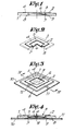
- the membrane for membrane switches according to the present invention showing the aforesaid and other advant d ges, therefore consists mainly of a profiled top layer 2 made of a resilient material and an underlying supporting layer 1 provided with an opening 3, said top layer 2 showing a recess fitting in said opening 3 and consisting of side-walls 5 and a part hanging therebetween and having the shape of a spherical segment forming the proper membrane 6.
- the membrane according to the present invention mainly consists of two layers glued together, viz. a supporting layer 1 and a profiled top layer 2 applied thereto.
- said supporting layer 1 consists of a sheet of, e.g., 1.5 mm thickness made of an electrically insulating or isolating material such as, e.g., plastic, wherein an opening 3 of about 1.5 cm xl.5 cm has been provided.
- the top layer 2 which is specifically represented in figure 2, consists of a relatively flexible, profiled material having a thickness of, e.g., about 0.25 mm. It consists of a flat part 4 of folded down rims or side-walls 5 ano of a spherical part applied between said walls 5 and constituting the membrane 6 proper.
- the form and the size of the profile formed by said side-walls 5 and the membrane 6 correspond with those of the opening 3 in the supporting layer 1.
- the top layer 2 is fixeo to said supporting layer 1, e.g. by means of an adhesive, in such a way that the profile formed by the side-walls 5 and the membrane 6 is just in the opening 3 of said supporting layer 1, so that said memorane 6 is suspendeo as it were to said side-walls 5.
- the edge 7 of the membrane 6, or in other words the junction of the membrane 6 and the side-walls 5, is not lower than the bottom side 8 of the supporting layer 1, but finds itself at a very small distance above it.
- the side-walls 5 show a certain clearance with respect to the inner wall 9 of opening 3 in the supporting layer 1 so that said side-walls 5 can move freely when the membrane 6 expands or is deformed when being energized.
- the membrane switch according to the present invention mainly consists, at the one hand, of three layers preferably glued together, viz. an under-layer 10 and the aforementioned supporting layer 1 and top layer 2, and, on the other hand, of two electrical contact elements 11 and 12.
- Said under-layer 10 consists of a flat sheet to which the contact element 11 has been applied in the form of an electrically conductive strip.
- said under-layer 10 constitutes the basis for taking up the pressure forces on the proper membrane 6 when the switch is operated, it is made, of course, either of a sufficiently strong material or of a foil that is stuck to a solid base.
- the supporting layer 1 and the top layer 2 are applied, such as they are represented in figure 1, e.g. by means of a glue.
- Said second contact element 12 is provided at the underside of the top layer 2 and so runs the entire underside of the membrane 6 proper.
- Each of both contact elements 11 and 12 consists of a stratum of silver, graphite, a mixture of both or any other suitable material, which is applied to the under-layer 10 and the underside of said top layer 2 by means of any process suited for that purpose.
- the contact place of both contact elements 11 and 12 is in the centre of opening 3 of said supporting layer 1.
- said membrane 6 should only be at a small distance above the under-layer 10 such that it cannot completely bend and that upon being released it comes back in its contactless position.
- the force K to be exerted thereby is proportional to the thickness of the material of said top layer 2 as well as to the curvature of said membrane 6.
- the opening 3 in the supporting layer 1 and the corresponding profile of the membrane 6 proper may have any shape and be rectangular, pentagonal, hexagonal or circular or yet have some other shape. If opening 3 is polygonal, the angles are preferably rounded off.
- the different components can be connected with each other in various ways, e.g. by keeping them clamped together by means of a fixture not represented in the figures. But preferably, however, a double-face sticking supporting layer 1 is used, which, e.g., is first applied to the under-layer 10 and to which the top layer 2 is adhered afterwards.
- the contact elements 11 and 12 consist of thin metal strips that are stuck to the under-layer 10 and the top layer 2 respectively.
- said under-layer 10 may consist of a conductive material, whereby it is not necessary any longer that a separate contact element 11 be used.
- a plurality of such a membrane switch or the membrane itself can be provided very simply on a control panel.
- the three layers 1, 2 and 10 are larger, wherein the supporting layer 1 but also top layer 2 have many openings 3, which top layer possesses as many profilings and spherical segments or membranes 6.
- the under-layer 10 as well as both contact elements 11-12 can also be replaced by switching elements known by themselves, the construction formed by the supporting layer 1 and the top layer 2 then taking care of a proper sealing.
- two contact elements are provided at the under-layer 10, all this such that the contact element 12 upon depression of the membrane 6 establishes a junction between both first elements.
- the contact strips used herein can have any form.
- openings are provided for allowing the air under the membrane 6 to escape when the latter is being depressea.
- the top layer 2 can be provided with all kinds of inscriptions and indications. If said top layer 2 is transparent or translucent, such an inscription can also be provided at the underside of said membrane 6.
Landscapes
- Push-Button Switches (AREA)
- Measurement And Recording Of Electrical Phenomena And Electrical Characteristics Of The Living Body (AREA)
- Solid State Image Pick-Up Elements (AREA)
- Measurement Of The Respiration, Hearing Ability, Form, And Blood Characteristics Of Living Organisms (AREA)
Priority Applications (1)
| Application Number | Priority Date | Filing Date | Title |
|---|---|---|---|
| AT86200819T ATE67342T1 (de) | 1985-05-22 | 1986-05-12 | Membran fuer membranschalter und die dazu gehoerigen elemente. |
Applications Claiming Priority (2)
| Application Number | Priority Date | Filing Date | Title |
|---|---|---|---|
| BE2/60691A BE902471A (nl) | 1985-05-22 | 1985-05-22 | Membraan voor membraanschakelaar en samenstellende elementen hiervan. |
| BE260691 | 1985-05-22 |
Publications (3)
| Publication Number | Publication Date |
|---|---|
| EP0202711A2 true EP0202711A2 (de) | 1986-11-26 |
| EP0202711A3 EP0202711A3 (en) | 1989-03-01 |
| EP0202711B1 EP0202711B1 (de) | 1991-09-11 |
Family
ID=3865748
Family Applications (1)
| Application Number | Title | Priority Date | Filing Date |
|---|---|---|---|
| EP86200819A Expired EP0202711B1 (de) | 1985-05-22 | 1986-05-12 | Membran für Membranschalter und die dazu gehörigen Elemente |
Country Status (5)
| Country | Link |
|---|---|
| US (1) | US4695681A (de) |
| EP (1) | EP0202711B1 (de) |
| AT (1) | ATE67342T1 (de) |
| BE (1) | BE902471A (de) |
| DE (1) | DE3681342D1 (de) |
Cited By (4)
| Publication number | Priority date | Publication date | Assignee | Title |
|---|---|---|---|---|
| GB2208039A (en) * | 1987-08-15 | 1989-02-15 | Harboro Rubber Company Limited | Manufacture of switch pad arrays |
| US5132496A (en) * | 1989-07-05 | 1992-07-21 | Acer Inc. | Membrane switch |
| EP1010964A1 (de) | 1998-12-16 | 2000-06-21 | Etat Français représenté par le Délégué Général pour l' Armement | Vorrichtung zum Zünden eines Detonators |
| FR2950193A1 (fr) * | 2009-09-15 | 2011-03-18 | Nicomatic Sa | Commutateur a effet tactile |
Families Citing this family (9)
| Publication number | Priority date | Publication date | Assignee | Title |
|---|---|---|---|---|
| US5200679A (en) * | 1990-02-22 | 1993-04-06 | Graham Douglas F | Artificial hand and digit therefor |
| US5670760A (en) * | 1995-10-24 | 1997-09-23 | Golden Books Publishing Company, Inc. | Multi-switch membrane-switch assembly |
| US5828016A (en) * | 1996-02-12 | 1998-10-27 | Lucas Automation And Control Engineering, Inc. | Low profile tactile switch |
| US20030051983A1 (en) * | 2001-03-07 | 2003-03-20 | Lahr Roy J. | Membrane keyswitch for an expandable keyboard and an expandable keyboard device |
| USD467882S1 (en) | 2001-03-12 | 2002-12-31 | Citizen Electronics Co., Ltd. | Depression switch |
| USD467880S1 (en) | 2001-03-12 | 2002-12-31 | Citizen Electronics Co., Ltd. | Depression switch |
| USD467881S1 (en) | 2001-03-12 | 2002-12-31 | Citizen Electronics Co., Ltd. | Depression switch |
| FR2859817B1 (fr) * | 2003-09-17 | 2006-06-02 | Itt Mfg Enterprises Inc | Contacteur de petite epaisseur |
| US7832900B2 (en) * | 2008-07-10 | 2010-11-16 | Simon Avitan | Lightbulb with envelope-fracture responsive electrical disconnect means |
Family Cites Families (12)
| Publication number | Priority date | Publication date | Assignee | Title |
|---|---|---|---|---|
| US2798130A (en) * | 1953-05-22 | 1957-07-02 | Cutler Hammer Inc | Electric switch devices |
| DE1089037B (de) * | 1958-04-12 | 1960-09-15 | Eduard Hermle | Wasserdichte Anordnung mehrerer elektrischer Stoesselschalter |
| US3760137A (en) * | 1970-10-05 | 1973-09-18 | Alps Electric Co Ltd | Matrix push-button switch |
| GB1361459A (en) * | 1971-08-05 | 1974-07-24 | Standard Telephones Cables Ltd | Electrical contact units |
| US3845260A (en) * | 1972-08-07 | 1974-10-29 | Allied Chem | Pressure sensing switch with movable contact diaphragm |
| FR2196515B1 (de) * | 1972-08-18 | 1977-09-16 | Matsushita Electric Industrial Co Ltd | |
| US3860771A (en) * | 1973-10-29 | 1975-01-14 | Chomerics Inc | Keyboard switch assembly with dome shaped actuator having associated underlying contactor means |
| US4127752A (en) * | 1977-10-13 | 1978-11-28 | Sheldahl, Inc. | Tactile touch switch panel |
| US4127758A (en) * | 1977-10-13 | 1978-11-28 | Sheldahl, Inc. | Tactile layer having hinged dome |
| US4194097A (en) * | 1978-06-12 | 1980-03-18 | Ncr Corporation | Membrane keyboard apparatus with tactile feedback |
| US4245138A (en) * | 1978-11-17 | 1981-01-13 | Rogers Corporation | Tactile element and keyboard including the tactile element |
| US4322587A (en) * | 1979-12-06 | 1982-03-30 | Rogers Corporation | Keyboard device |
-
1985
- 1985-05-22 BE BE2/60691A patent/BE902471A/nl not_active IP Right Cessation
-
1986
- 1986-05-12 AT AT86200819T patent/ATE67342T1/de not_active IP Right Cessation
- 1986-05-12 DE DE8686200819T patent/DE3681342D1/de not_active Expired - Lifetime
- 1986-05-12 EP EP86200819A patent/EP0202711B1/de not_active Expired
- 1986-05-15 US US06/863,341 patent/US4695681A/en not_active Expired - Lifetime
Cited By (6)
| Publication number | Priority date | Publication date | Assignee | Title |
|---|---|---|---|---|
| GB2208039A (en) * | 1987-08-15 | 1989-02-15 | Harboro Rubber Company Limited | Manufacture of switch pad arrays |
| US5132496A (en) * | 1989-07-05 | 1992-07-21 | Acer Inc. | Membrane switch |
| EP1010964A1 (de) | 1998-12-16 | 2000-06-21 | Etat Français représenté par le Délégué Général pour l' Armement | Vorrichtung zum Zünden eines Detonators |
| FR2787568A1 (fr) | 1998-12-16 | 2000-06-23 | France Etat | Dispositif de mise a feu d'une amorce |
| FR2950193A1 (fr) * | 2009-09-15 | 2011-03-18 | Nicomatic Sa | Commutateur a effet tactile |
| WO2011032923A1 (fr) * | 2009-09-15 | 2011-03-24 | Nicomatic Sa | Commutateur à effet tactile |
Also Published As
| Publication number | Publication date |
|---|---|
| DE3681342D1 (de) | 1991-10-17 |
| ATE67342T1 (de) | 1991-09-15 |
| EP0202711A3 (en) | 1989-03-01 |
| US4695681A (en) | 1987-09-22 |
| BE902471A (nl) | 1985-09-16 |
| EP0202711B1 (de) | 1991-09-11 |
Similar Documents
| Publication | Publication Date | Title |
|---|---|---|
| EP0202711A2 (de) | Membran für Membranschalter und die dazu gehörigen Elemente | |
| US4303811A (en) | Kit for use in the construction of custom prototype membrane switch panels | |
| US4065649A (en) | Pressure sensitive matrix switch having apertured spacer with flexible double sided adhesive intermediate and channels optionally interposed between apertures | |
| US4056701A (en) | Low profile lighted push button switch | |
| US4302647A (en) | Membrane touch switches | |
| EP0203068B1 (de) | Verbesserungen der schalter und der tastaturen | |
| US4463234A (en) | Tactile feel membrane switch assembly | |
| US4314117A (en) | Membrane contact switch | |
| KR860006759A (ko) | 전자악기용 건반스위치 장치 | |
| KR850008011A (ko) | 막 키보드 스위치 | |
| JPS593824A (ja) | パネルキ−ボ−ド | |
| EP0322515A2 (de) | Tastatur mit Entlüftung | |
| US4892988A (en) | Membrane panel switch | |
| US4194099A (en) | Control panel overlay | |
| KR870007459A (ko) | 표면상의 지점의 좌표를 결정하기 위한 감촉 스크린 | |
| GB2210507A (en) | Keyboard switch | |
| WO1986007653A1 (en) | Membrane switch with pivotable rocker | |
| JP2000182461A (ja) | キートップ板の製造方法 | |
| JP4187717B2 (ja) | クリックばね付きシート及びこれを用いたスイッチ装置 | |
| JPS616223U (ja) | 照光式パネルスイツチ | |
| JPH0439620Y2 (de) | ||
| EP0087918A1 (de) | Tastaturschalter | |
| US5670760A (en) | Multi-switch membrane-switch assembly | |
| JPS6220110Y2 (de) | ||
| JPH0752614B2 (ja) | キ−ボ−ド装置 |
Legal Events
| Date | Code | Title | Description |
|---|---|---|---|
| PUAI | Public reference made under article 153(3) epc to a published international application that has entered the european phase |
Free format text: ORIGINAL CODE: 0009012 |
|
| AK | Designated contracting states |
Kind code of ref document: A2 Designated state(s): AT CH DE FR GB IT LI LU NL SE |
|
| RAP1 | Party data changed (applicant data changed or rights of an application transferred) |
Owner name: VELLEMAN-SWITCH, NAAMLOZE VENNOOTSCHAP |
|
| PUAL | Search report despatched |
Free format text: ORIGINAL CODE: 0009013 |
|
| AK | Designated contracting states |
Kind code of ref document: A3 Designated state(s): AT CH DE FR GB IT LI LU NL SE |
|
| 17P | Request for examination filed |
Effective date: 19890810 |
|
| 17Q | First examination report despatched |
Effective date: 19900330 |
|
| GRAA | (expected) grant |
Free format text: ORIGINAL CODE: 0009210 |
|
| RAP3 | Party data changed (applicant data changed or rights of an application transferred) |
Owner name: VELLEMAN-SWITCH, NAAMLOZE VENNOOTSCHAP |
|
| AK | Designated contracting states |
Kind code of ref document: B1 Designated state(s): AT CH DE FR GB IT LI LU NL SE |
|
| REF | Corresponds to: |
Ref document number: 67342 Country of ref document: AT Date of ref document: 19910915 Kind code of ref document: T |
|
| REF | Corresponds to: |
Ref document number: 3681342 Country of ref document: DE Date of ref document: 19911017 |
|
| ET | Fr: translation filed | ||
| ITF | It: translation for a ep patent filed | ||
| PGFP | Annual fee paid to national office [announced via postgrant information from national office to epo] |
Ref country code: SE Payment date: 19920505 Year of fee payment: 7 |
|
| PGFP | Annual fee paid to national office [announced via postgrant information from national office to epo] |
Ref country code: FR Payment date: 19920506 Year of fee payment: 7 |
|
| PGFP | Annual fee paid to national office [announced via postgrant information from national office to epo] |
Ref country code: GB Payment date: 19920508 Year of fee payment: 7 Ref country code: CH Payment date: 19920508 Year of fee payment: 7 |
|
| PGFP | Annual fee paid to national office [announced via postgrant information from national office to epo] |
Ref country code: AT Payment date: 19920513 Year of fee payment: 7 |
|
| PLBI | Opposition filed |
Free format text: ORIGINAL CODE: 0009260 |
|
| PGFP | Annual fee paid to national office [announced via postgrant information from national office to epo] |
Ref country code: LU Payment date: 19920701 Year of fee payment: 7 |
|
| 26 | Opposition filed |
Opponent name: METAGRA N.V. Effective date: 19920610 |
|
| NLR1 | Nl: opposition has been filed with the epo |
Opponent name: METAGRA N.V. |
|
| EPTA | Lu: last paid annual fee | ||
| PG25 | Lapsed in a contracting state [announced via postgrant information from national office to epo] |
Ref country code: LU Free format text: LAPSE BECAUSE OF NON-PAYMENT OF DUE FEES Effective date: 19930512 Ref country code: GB Effective date: 19930512 Ref country code: AT Effective date: 19930512 |
|
| PG25 | Lapsed in a contracting state [announced via postgrant information from national office to epo] |
Ref country code: SE Effective date: 19930513 |
|
| PG25 | Lapsed in a contracting state [announced via postgrant information from national office to epo] |
Ref country code: LI Effective date: 19930531 Ref country code: CH Effective date: 19930531 |
|
| GBPC | Gb: european patent ceased through non-payment of renewal fee |
Effective date: 19930512 |
|
| PG25 | Lapsed in a contracting state [announced via postgrant information from national office to epo] |
Ref country code: FR Effective date: 19940131 |
|
| REG | Reference to a national code |
Ref country code: CH Ref legal event code: PL |
|
| REG | Reference to a national code |
Ref country code: FR Ref legal event code: ST |
|
| PLBN | Opposition rejected |
Free format text: ORIGINAL CODE: 0009273 |
|
| STAA | Information on the status of an ep patent application or granted ep patent |
Free format text: STATUS: OPPOSITION REJECTED |
|
| 27O | Opposition rejected |
Effective date: 19940630 |
|
| NLR2 | Nl: decision of opposition | ||
| EUG | Se: european patent has lapsed |
Ref document number: 86200819.0 Effective date: 19931210 |
|
| PGFP | Annual fee paid to national office [announced via postgrant information from national office to epo] |
Ref country code: DE Payment date: 20050311 Year of fee payment: 20 |
|
| PG25 | Lapsed in a contracting state [announced via postgrant information from national office to epo] |
Ref country code: IT Free format text: LAPSE BECAUSE OF NON-PAYMENT OF DUE FEES;WARNING: LAPSES OF ITALIAN PATENTS WITH EFFECTIVE DATE BEFORE 2007 MAY HAVE OCCURRED AT ANY TIME BEFORE 2007. THE CORRECT EFFECTIVE DATE MAY BE DIFFERENT FROM THE ONE RECORDED. Effective date: 20050512 |
|
| PGFP | Annual fee paid to national office [announced via postgrant information from national office to epo] |
Ref country code: NL Payment date: 20050526 Year of fee payment: 20 |
|
| PG25 | Lapsed in a contracting state [announced via postgrant information from national office to epo] |
Ref country code: NL Free format text: LAPSE BECAUSE OF EXPIRATION OF PROTECTION Effective date: 20060512 |
|
| NLV7 | Nl: ceased due to reaching the maximum lifetime of a patent |
Effective date: 20060512 |