EP0202103B1 - Fastener feeder assembly for use with fastener driver apparatus - Google Patents
Fastener feeder assembly for use with fastener driver apparatus Download PDFInfo
- Publication number
- EP0202103B1 EP0202103B1 EP86303617A EP86303617A EP0202103B1 EP 0202103 B1 EP0202103 B1 EP 0202103B1 EP 86303617 A EP86303617 A EP 86303617A EP 86303617 A EP86303617 A EP 86303617A EP 0202103 B1 EP0202103 B1 EP 0202103B1
- Authority
- EP
- European Patent Office
- Prior art keywords
- fastener
- fasteners
- driver
- assembly
- piston
- Prior art date
- Legal status (The legal status is an assumption and is not a legal conclusion. Google has not performed a legal analysis and makes no representation as to the accuracy of the status listed.)
- Expired - Lifetime
Links
Images





Classifications
-
- B—PERFORMING OPERATIONS; TRANSPORTING
- B25—HAND TOOLS; PORTABLE POWER-DRIVEN TOOLS; MANIPULATORS
- B25B—TOOLS OR BENCH DEVICES NOT OTHERWISE PROVIDED FOR, FOR FASTENING, CONNECTING, DISENGAGING, OR HOLDING
- B25B23/00—Details of, or accessories for, spanners, wrenches, screwdrivers
- B25B23/02—Arrangements for handling screws or nuts
- B25B23/04—Arrangements for handling screws or nuts for feeding screws or nuts
- B25B23/045—Arrangements for handling screws or nuts for feeding screws or nuts using disposable strips or discs carrying the screws or nuts
Definitions
- the present invention relates to a fastener feeder assembly for use with fastener driver apparatus.
- Power tools are used in a number of applications for driving threaded or rotary entry fasteners into a workpiece.
- drywall panels, metal panels or the like have to be affixed to wood or metal studs or other support elements in constructing internal walls of a building.
- Rotary entry fasteners such as screws, can be used to affix such panels to the support elements by driving the fasteners through the panels into the support elements.
- a power screwdriver is used for driving the screws through the panels and into the support elements. These screwdrivers may be electrically or pneumatically powered. In either case, the power screwdriver may include a housing with an integral handle and a rotary driving bit extending from the housing.
- the bit In a conventional fastener driving operation, the bit is adapted to be mated with a slot structure in the head of the fastener to be driven. As the screwdriver is moved toward the workpiece, the end of the bit becomes disposed in the slot structure of the screw and the screw is rotated and driven into the workpiece.
- individual fasteners In orderto position the fasteners for driving by the bit of the screwdriver, individual fasteners may be manually placed against the workpiece and held there until the screwdriver bit engages the fastener and the screw begins its penetration into the workpiece. Alternatively, the fastener might be held against the bit by having the driver bit magnetized. Manual handling of individual fasteners in this manner is slow, inconvenient and undesirable.
- the Applicants of the present application have developed fastener feeding apparatus to feed and properly position individual fasteners so that they can be driven into a workpiece by a power screwdriver.
- Two such devices are disclosed in United States Patent Nos. 3,910,324 and 3,930,297.
- the feeder mechanism disclosed in those patents are of the mechanical type that advance a flexible strip or carrier of fasteners from a housing containing a coiled strip of fasteners. These feeder mechanisms rely on the force exerted by the operator during the driving stroke to feed the fasteners.
- EP-A-0 058 986 describes a fastener feeder assembly for use with a fastener driving tool for driving fasteners into a workpiece, the fastener driving tool having a fastener driving means including a driver operable along a predetermined path through a manually operated driving stroke during which one of said fasteners is removed from a carrier on which the fasteners are retained, each fastener having an end portion adapted to engage the workpiece.
- the assembly for driving fasteners includes a fastener feeding means for feeding the carrier so that individual ones of said fasteners is positioned in sequence into said predetermined path for removal from the carrier and driving into the workpiece by the driver during a driving stroke.
- a mechanical fastener retaining means is optionally provided to maintain the orientation of the fasteners with respect to the workpiece as the fasteners are being driven into the workpiece during a driving stroke.
- the present invention provides a combination of a fastener assembly and a fastener driving tool for driving fasteners into a workpiece
- the fastener driving tool having a fastener driving means including a driver operable along a predetermined path through a driving stroke during which one of said fasteners is removably retained on a carrier and having an end portion adapted to engage the workpiece
- the fastener assembly including a fastener feeding means on said fastener assembly for feeding individual ones of said fasteners in sequence into said predetermined path and mechanical fastener retaining means for releasably retaining one of said fasteners in said predetermined path
- said fastener assembly characterised by control means including extend and retract means coupled to said fastener driving means and said fastener feeding means for effecting synchronized operation of said driver and the fastenerfeeding means said control means having cycles of operation, each of said cycles including a first static mode during which said extend and retract means are positioned such that said one of said fasteners is releasably
- a pneumatically controlled and operated fastener assembly and fastener driving tool combination results for supplying and positioning fasteners, such as screws having a head and a threaded shank portion, so that the fasteners can be driven into a workpiece by the power screwdriver.
- a fastener driving assembly including a fastener driving tool 20 having attached thereto a fastener feeder assembly which is generally designated as 22 and which includes a driver mechanism 36.
- the feeder and driver assembly 22 further includes a magazine assembly 24 in which is housed a fastener strip 26 comprised of a carrier member 28 and a plurality of fasteners 30.
- the fastener strip 26 is fed into a nose assembly 32 of the feeder and driver assembly 22 wherein one of the fasteners 30, such as a fastener 30a (Fig. 6), is positioned so that it can be driven into a workpiece (not shown), such as a wall panel or the like.
- the fastener 30a is driven into the workpiece by a driver member or bit 34 which is rotated by the fastener driving tool 20.
- the pneumatically operated feeder and driver mechanism 36 forming a part of the feeder and driver assembly 22 is attached to a front end 38 of the fastener driving tool 20 and has the nose assembly 32 mounted thereon.
- the feeder and driver assembly 22 is normally in a standby or static mode as illustrated in FIG. 6 of the drawings with a fastener 30a disposed in and projecting from the nose assembly 32 so as to be in a position to be driven into a workpiece.
- a trigger 40 of the fastener driving tool 20 Upon the actuation of a trigger 40 of the fastener driving tool 20, the bit 34 is rotated and an operator of the tool 20 pushes the fastener driving tool 20 towards the workpiece so that the fastener 30a is forced to the left as illustrated in FIG. 7 of the drawings and is driven into a workpiece.
- the feeder and driver mechanism 36 moves the fastener driving tool 20 and thereby the bit 34 to the right as viewed in FIG. 1 during a fire mode and a first portion of a return mode of the feeder and driver assembly 22. As a result, the bit 34 is returned to the position illustrated in FIG. 8 of the drawings.
- the fastener strip 26 is incrementally advanced so that the next one of the fasteners 30, such as fastener 30b, is positioned in the nose assembly 32 as illustrated in FIG. 8 of the drawings.
- the feeder and driver mechanism 36 moves the fastener driving tool 20 and thereby the bit 34 toward the fastener 30b whereby the fastener 30b is removed from the fastener strip 26 and advanced to a position illustrated in FIG. 6 with respect to the fastener 30a.
- the feeder and driver assembly 22 is again in its static or ready mode so that the fastener 30b can be driven into a workpiece.
- the fastener driving tool 20 shown in FIG. 1 is a pneumatic power screwdriver and is adapted to drive fasteners, such as the fasteners 30, which in the disclosed embodiment are screws, into drywall panels and the metal or wood studs onto which such panels are mounted.
- the fastener driving tool 20 includes a housing 44 from which extends a handle portion 46. Air from a pressurized source of air, such as a compressor, is supplied to a pneumatically operated motor (not shown) located in the housing 44 and enables the motor to provide a rotary motion to a bit holder 48 through a clutch 50 when the trigger 40 is depressed. While the disclosed fastener driving tool 20 is pneumatically operated, standard electric screwdrivers can be used as the driving tool in the same manner as the disclosed pneumatically operated screwdriver 20.
- the front portion 38 of the fastener driving tool 20 is secured to a mounting block 52 forming a part of the feeder and driver mechanism 36, which mounting block 52 has an opening 54 into which the front end 38 of the fastener driving tool 20 can be positioned.
- a retaining screw 56 compresses the opening 54 so as to hold the front end 38 of the fastener driving tool 20 in the opening 54.
- the feeder and driver mechanism 36 also has a cylinder housing 58 in which is disposed pneumatic circuitry for controlling the operation of the feeder and driver assembly 22.
- the cylinder housing 58 includes guide cylinders 60 and 62.
- a guide rod 64 is movably mounted within the cylinder 60 by a bearing 66 and is attached to the mounting block 52 by a screw 68.
- Another guide rod 70 is mounted to the mounting block 52 by a screw 72 and moves within the cylinder 62 in the cylinder housing 58.
- the guide rods 64 and 70 aid in guiding the mounting block 52 as it moves relative to the cylinder housing 58 during the operation of the feeder and driver mechanism 36.
- the cylinder housing 58 also includes an extend cylinder 74 in which is movably mounted an extend piston 76 having an 0-ring 78 to seal a portion of the cylinder 74.
- the extend piston 76 is also secured to the mounting block 52 by a screw 80. During the fire mode and a portion of the return mode, the extend piston 76 causes the mounting block 52 to move to the position shown in FIGS. 4 and 5.
- the feeder and driver mechanism 36 includes a retract rod 82 which is secured to the mounting block 52 by a screw 84.
- a retract piston 86 is movably mounted about the retract rod 82 and a piston seal 88 forms a seal about the rod 82.
- a fastener 90 attached to the end of the retract rod 82 forces the retract piston 86 to move to the right as viewed in FIG. 5 as the retract rod 82 moves in that direction.
- the retract piston 86 travels within a retract cylinder 92 within the cylinder housing 58.
- the retract rod 82 pulls the mounting block 52 to its static position during the second portion of the return mode.
- a fastener strip feeder mechanism 94 is disposed within the cylinder housing 58.
- the feeder mechanism 94 includes a pawl cylinder 96 which extends vertically in the cylinder housing 58 and in which is movably mounted a pawl piston 98.
- a feed pawl 100 is mounted within the pawl piston 98.
- the movement of the piston 98 within the pawl cylinder 96 is controlled by a feed piston 102 which is movably mounted within a feed cylinder 104.
- a chain link 106 is secured to the feed piston 102 by a feed pin 108 and a fastener 110.
- the chain link 106 is attached to a feed pivot plate 112 which pivots on a pivot 114 within a cavity 116 in the cylinder housing 58.
- the pivot plate 112 is attached to the pawl piston 98 by another chain link 118. Since the feed piston 102 is secured to the pawl piston 98 by means of the chain links 106 and 118 and the pivot plate 112, movement of the piston 102 from left to right in FIG. 4 translates into an up and down motion of the piston 98 within the feed cylinder 96. As a result, the cylinder housing 58 occupies a minimum amount of space between its front end 120 and its rear end 122 such that the entire length of the feeder and driver assembly 22 is minimized.
- the cylinder housing 58 also houses a stop valve 124 disposed within a stop valve cylinder 126.
- the stop valve 124 is actuated by the stop screw 42 and controls the extent to which the mounting block 52 moves towards the front end 120 of the cylinder housing 58 while one of the fasteners 30 is being driven into a workpiece.
- the cylinder housing 58 in addition has a channel 128 through which the driver bit 34 extends (FIG. 5).
- the driver bit 34 is held in the bit holder 48.
- a spring 130 is disposed about the bit holder 48 between the cylinder housing 58 and the mounting block 52. The spring 130 is compressed as the mounting block 52 is moved towards the front end 120 of the cylinder housing 58 during the installation of one of the fasteners 30 and assists in returning the mounting block 52 to the position shown in FIGS. 4 and 5 of the drawings during the fire mode and the first portion of the return mode.
- a cover plate 132 is secured to the rear end 122 of the cylinder housing 58 by fasteners 134 and 136.
- the feeder and driver assembly 22 includes a guard 138 which is attached to the mounting block 52 by screws 140 and 142 and moves about the cylinder housing 58 when the mounting block 52 moves relative to the cylinder housing 58 during the operation of the feeder and driver assembly 22.
- the magazine assembly 24 is maintained relative to the driving tool 20 by securing it to the mounting block 52 by means of a downwardly projecting leg 144 which is secured to the mounting block 52 by a fastener 146.
- the leg 144 is attached to a socket 148 projecting from a housing 150 of the magazine assembly 24.
- the housing 150 preferably is formed of a relatively lightweight, yet strong material such as a suitable plastic or the like.
- the housing 150 is generally circular in outline so that it can receive the fastener strip 26 when it is rolled into a coil.
- a lower peripheral wall 152 of the housing 150 may be swung about a hinge 154 and is latched in a closed position by a latch assembly 156.
- the door 152 When the latch 156 is released, the door 152 can be swung about the hinge 154 so that the inner part of the housing 150 is accessible and can be filled with a coiled fastener strip 26.
- the door 152 When the door 152 is again secured in its closed position as shown in FIG. 1 of the drawings, a portion of the fastener strip 26 is fed out of the housing 150 to the nose assembly 32.
- the portion of the fastener strip 26 extending between the housing 150 and the nose assembly 32 is twisted through a substantial angle so that there is no interference between the fastener strip 26 and a workpiece and the fastener strip 26 can flex as the driving tool 20 and the magazine assembly 24 moves relative to the nose assembly 32.
- each fastener 30 includes a shank portion 158, at least a portion of which is threaded, a tip 160 at the entry end of the shank portion 158 and a head 162 at the opposite end of the shank 158.
- the head 162 is provided with a drive slot structure which is complementary to a tip portion 164 of the driver bit 34.
- the tip portion 164 of the bit 34 is inserted into the complementary drive slot of the head 162, the rotation of the driver bit 34 causes the fastener 30 to be rotated in accordance with known practices.
- the fastener strip 26 is of the type disclosed in United States Patent No. 3,885,669, assigned to the Applicants of the present application.
- the fastener strip 26 includes the carrier member 28 which is in the form of an elongated strip of flexible plastic material.
- the carrier member 28 is continuous throughout the length of the fastener strip 26 and, as illustrated in connection with the fastener 30c in Fig. 1, includes a tab 166 which extends from one side of the carrier strip 28 and which is designed to receive the fastener 30c in a slot located in the tab 166 such that the fastener 30c is frictionally retained therein with the shank portion 158 of the fastener 30c extending generally parallel to the plane of the carrier member 28.
- the fastener strip 26 can be provided with a tab extending from the other end of the carrier member 28 in order that the fasteners 30 are more securely affixed to the fastener strip 26.
- the carrier member 28 also is provided with a series of openings 168, one of which openings is longitudinally placed along the carrier member 28 between each of the tabs 166.
- the openings 168 are adapted to receive the feed pawl 100 in order for the fastener strip 26 to be incrementally advanced during the operation of the feeder and driver assembly 22.
- the feeder and driver mechanism 36 which forms a part of the feeder and driver assembly 22 is a pneumatically operated mechanism. Pressurized air from an air reservoir, such as a compressor or the like, is supplied to a port 170 on the lower portion of the cylinder housing 58 via an appropriate hose or the like (not shown).
- an air reservoir such as a compressor or the like
- FIGS. 9-12 disclose in schematic form the pneumatic circuitry for the feeder and driver mechanism 36 during various modes or phases of the operation of the feeder and driver assembly 22.
- the feeder and driver assembly 22 is shown therein in its static or ready mode so that one of the fasteners, such as the fastener 30a shown in FIG. 6, is ready for being driven into a workpiece.
- the fastener 30a is held in a nose chuck 172 consisting of jaws 174 and 176.
- the jaws 174 and 176 are biased to hold the fastener 30a as shown in FIG. 6 so that the fastener 30a has a portion of its shank 158 extending out from a nose guard 178.
- the bit 34 has its tip portion 164 inserted into the head 162 of the fastener 30a.
- the fastener 30a may be positioned within a pilot hole in the workpiece into which it is to be driven or against the workpiece, if no pilot hole is formed therein, prior to the fastener 30a being rotated and driven by the bit 34. It is noted that when the fastener 30a has been positioned as shown in FIG. 6, the fastener 30a has been removed from the fastener strip 26 as will be discussed in more detail below.
- reservoir air i.e., pressurized air
- the reservoir air is also supplied through a duct 186 to the portion of the cylinder 126 between O-rings 188 and 190 on the stop valve 124 and from there through another duct 192 to the portion of the feed cylinder 104 between an O-ring 194 on the feed piston 102 and an 0-ring 195 which seals the cylinder 104 along the cover plate 132.
- That portion of the feed cylinder 104 is connected via a duct 196 to the retract cylinder 92 so that reservoir air is supplied to the retract cylinder 92 between the piston seal 88 and the retract piston 86.
- Air vents 198, 200, and 202 are provided in the cylinder housing 58 to connect various portions of the pneumatic circuitry to atmosphere.
- the air vent 198 vents that portion of the stop valve cylinder 126 between the 0-ring 190 and an 0-ring 204 to atmosphere. Since that portion of the stop valve cylinder 126 between the O-rings 190 and 204 is connected to the extend cylinder 74 by a duct 206, the portion of the extend cylinder 74 to the left, as viewed in FIG. 9, of the O-ring 78 on the extend piston 76 is at atmospheric pressure.
- the air vent 200 connects the portion of the stop valve cylinder 126 to the left, as viewed in FIG. 9, of the 0-ring 188 to atmosphere.
- a duct 208 connects that portion of the stop valve cylinder 126 and therefore the vent 200 to the portion of the extend cylinder 74 to the right of the O-ring 78. Consequently, the entire extend piston cylinder 74 is at atmospheric pressure.
- the air vent 202 is coupled to the feed piston cylinder 104 between the O-rings 184 and 194 resulting in that portion of the piston cylinder 104 being maintained at atmospheric pressure.
- the retract rod 82 positions the mounting block 52 as illustrated in FIG. 9 of the drawings due to the fact that reservoir air supplied to the cylinder 92 forces the retract piston 86 against a spacer 210.
- the feed piston 102 positions the pawl piston 98 and consequently the feed pawl 100 in the position shown in FIG. 9 such that one of the fasteners 30 will be in alignment with the driver bit 34.
- the feed piston 102 is placed in this position due to the fact that reservoir air supplied to the larger diameter of the feed piston 102 between the O-rings 194 and 195 overcomes the force exerted by the reservoir air that is supplied to the smaller diameter portion of the feed piston 102 between the O-rings 182 and 184.
- the extend piston 76 is allowed to move within the cylinder 74 as the mounting block 52 is moved to the left in FIG. 9 by the retract piston 82.
- the stop valve 124 is in its ready mode as shown in FIG. 9 due to the presence of reservoir air between the O-rings 188 and 190.
- an operator can drive a fastener, such as the fastener 30a shown in FIG. 6, into a workpiece.
- a fastener such as the fastener 30a shown in FIG. 6
- the operator then pushes against the handle 46 of the fastener driving tool 22 causing the mounting block 52 to move toward the workpiece.
- This movement of the mounting block 52 forces the bit holder 48 and the bit 34 to push against the fastener 30a and the fastener 30a is thereby installed into the workpiece.
- the fastener 30a forces open the jaws 174 and 176 of the nose chuck 172 as illustrated in FIG. 7 of the drawings.
- an end 212 of the stop screw 42 engages a stem 214 of the stop valve 24 projecting through the cover plate 132.
- the stop valve 24 is moved to the position shown in FIG. 10 of the drawings initiating what can be termed the fire mode of the feeder and driver assembly 22.
- the stop screw 42 can be adjusted relative to the mounting block 52 and locked in place by a lock nut 216. Consequently, the stop valve 124 acts as a depth control to determine the depth to which one of the fasteners 30 will be driven into a workpiece. More specifically, the location of the mounting block 52 when the fire mode is initiated as illustrated in FIG. 10 of the drawings determines the extent to which the bit 34 has driven a fastener, such as the fastener 30a in FIG. 7, out from the nose assembly 32 into a workpiece. If the stop screw 42 is adjusted so that the end 212 of the stop screw 42 is further to the left as viewed in FIG. 9, the end 212 will engage the stem 214 when the mounting block 52 is further to the right as viewed in FIG. 9. In this event, the fasteners 30 being driven into a workpiece will not be driven into the workpiece as deep as when the stop screw 42 is adjusted so that the tip 212 of the stop screw 42 is further to the right as viewed in FIG. 9.
- the O-ring 188 passes the air vent 200 such that the duct 192 is vented to atmosphere resulting in the venting to atmosphere of the portion of the feed cylinder 104 between the O-ring 194 and the piston seal 195. Since reservoir air is still supplied through the duct 180 to the feed piston 104 between the O-rings 182 and 184, the feed piston 102 will move in the direction indicated by the arrows in FIG. 10 of the drawings. This movement of the feed piston 102 causes the feed pivot plate 112 to pivot about the pivot 114 pulling, via the chain link 118, the pawl piston 98 downwardly, as viewed in FIG. 10, in the feed cylinder 96.
- the feed pawl 100 moves downwardly as viewed in FIGS. 1 and 10 along the carrier member 28 of the fastener strip 26 that is held against the feed pawl 100 in the nose assembly 32.
- the feed pawl 100 has a cam surface 218 which permits the pawl 100 to slip past the opening 168 in the carrier member 28 when the feed piston 98 is moved as illustrated in FIG. 10, the feed pawl 100 does not move the fastener strip 26.
- the O-ring 194 passes the air duct 196 so that the air duct 196 becomes vented to atmosphere because it is now connected to the air vent 202. Consequently, the retract cylinder 92 between the retract piston 86 and the piston seal 88 is placed at atmospheric pressure so that the retract piston 86 can be moved towards the piston seal 88.
- the movement of the stop valve 124 also results in the movement of the 0-ring 190 past the duct 186 so that reservoir air is now supplied to the stop valve cylinder 126 between the O-rings 190 and 204. Reservoir air is also supplied via duct 206 to the extend cylinder 74 to the left of 0-ring 78 as viewed in FIG. 10.
- the extend piston 76 Since the extend cylinder 74 to the right of the O-ring 78 is maintained at atmospheric pressure, via an opening in the cover plate 132 about the extend cylinder 74, the extend piston 76 is forced to the right as viewed in FIG. 10 of the drawings. The movement of the extend piston 76 in this manner forces the mounting block 52 to the right as viewed in FIG. 10. This movement of the mounting block 52 is guided by the guide rods 64 and 70.
- FIG. 11 of the drawings schematically illustrates the feeder and driver mechanism 36 at a point in time during what can be termed a first portion of the return mode of the feeder and driver assembly 22.
- reservoir air continues to be supplied to the extend cylinder 74 forcing the extend piston 76 further to the right as viewed in FIG. 11.
- the fastener 90 on the retract rod 82 engages the retract piston 86 and moves it away from the spacer 210 so as to move it toward the piston seal 88 as illustrated in FIG. 11 of the drawings.
- the feed piston 102 is maintained in the position shown in FIG.
- the feed pawl 100 is in its lowered position illustrated in FIG. 11 and is in alignment with the next one of the openings 168 in the carrier member 28 of the fastener strip 26 so that it will be in a position to incrementally advance the carrier member 28 when the feeder and driver assembly 22 enters the second portion of its return mode.
- the stop valve 124 remains in its depressed or actuated position due to the fact that reservoir air continues to be supplied to the stop valve cylinder 126 between O-rings 190 and 204 and the remaining portions of the stop valve cylinder 126 are maintained at atmospheric pressure. It is noted that at the point in time during the return mode illustrated in FIG. 11, the 0-ring 78 on the extend piston 76 is still to the left of the duct 208. As the extend piston 76 is forced further to the right as viewed in FIG. 11, the 0-ring 78 will move past the duct 208 resulting in the feeder and driver assembly 22 transferring into the second portion of its return mode.
- the portion of the extend cylinder 74 to the left of the O-ring 78 is also vented to atmosphere because it is coupled to the air vent 200 through the lefthand portion of the stop valve cylinder 126 and the duct 208. Since no reservoir air is supplied to the extend cylinder 74, the extend piston 76 will cease moving to the right as viewed in FIG. 12 such that the mounting block 52 no longer will be moved in that direction. At this point in time, the bit holder 130 has also been retracted to the right in FIG. 12 so that the bit 34 is positioned as illustrated in FIG. 8 of the drawings.
- the 0-ring 194 passes the duct 196 and reservoir air is supplied from the feed cylinder 104 through the duct 196 to the retract cylinder 92 between the retract piston 86 and the piston seal 88.
- the supplying of reservoir air to the retract cylinder 92 in this manner forces the retract piston 86 to move to the left as viewed in FIG. 12 and the retract piston 86 engages the fastener 90 forcing the retract rod 82 to also move towards the left as viewed in FIG. 12 of the drawing. Movement of the retract rod 82 forces the mounting block 52 to also move to the left as viewed in FIG. 12.
- the movement of the mounting block 52 is not inhibited by the extend piston 76 because the extend cylinder 74 is maintained at atmospheric pressure since the air vent 198 is now coupled to the lefthand portion of the extend cylinder 74 through the duct 206.
- the mounting block 52 moves to the left in FIG. 12 toward its static or ready position as illustrated in FIG. 9 of the- drawings, the bit holder 130 and therefore the bit 34 are moved toward the fastener 30b as shown in FIG. 8 which has been positioned in the nose assembly 32 in alignment with the bit 34 by the incremental advance of the carrier member 28 of the fastener strip 26 due to the movement of the feed pawl 100.
- the mounting block 52 will proceed to move toward the rear end 122 of the cylinder housing 58 due to the continued supplying of reservoir air to the retract cylinder 92 between the retract piston 86 and the piston seal 88.
- the mounting block 52 will come to its static or ready position as illustrated in FIG. 9 when the retract piston 86 engages the spacer 210.
- the tip 164 of the bit 34 Prior to the mounting block 52 being positioned as illustrated in FIG. 9 of the drawings, the tip 164 of the bit 34 will engage the head 162 of the fastener 30b forcing the fastener 30b be removed from the slot in the tab 166 on the carrier member 28 in which the fastener 30b is held.
- the fastener 30b is then forced between the nose jaws 174 and 176 until it reaches the position illustrated in connection with the fastener 30a in FIG. 6 of the drawings.
- the bit 34 and the fastener 30b will be positioned as shown in FIG. 6 when the mounting block 52 is positioned as shown in FIG. 9 with the retract piston 86 against the spacer 210.
- the feeder and driver assembly 22 is now in its static or ready position to again be actuated by an operator installing the next screw 30b into a workpiece.
- the feeder and driver assembly 22 can be utilized at a construction site or any other location where a source of pressurized air is available. Moreover, the feeder and driver assembly 22 can be made relatively lightweight and not cumbersome as compared to a mechanism which would require an electric motor or the like to operate the feeder and driver mechanism.
Landscapes
- Engineering & Computer Science (AREA)
- Mechanical Engineering (AREA)
- Details Of Spanners, Wrenches, And Screw Drivers And Accessories (AREA)
- Portable Nailing Machines And Staplers (AREA)
Description
- The present invention relates to a fastener feeder assembly for use with fastener driver apparatus.
- Power tools are used in a number of applications for driving threaded or rotary entry fasteners into a workpiece. For example, drywall panels, metal panels or the like have to be affixed to wood or metal studs or other support elements in constructing internal walls of a building. Rotary entry fasteners, such as screws, can be used to affix such panels to the support elements by driving the fasteners through the panels into the support elements. In many applications, a power screwdriver is used for driving the screws through the panels and into the support elements. These screwdrivers may be electrically or pneumatically powered. In either case, the power screwdriver may include a housing with an integral handle and a rotary driving bit extending from the housing. In a conventional fastener driving operation, the bit is adapted to be mated with a slot structure in the head of the fastener to be driven. As the screwdriver is moved toward the workpiece, the end of the bit becomes disposed in the slot structure of the screw and the screw is rotated and driven into the workpiece. In orderto position the fasteners for driving by the bit of the screwdriver, individual fasteners may be manually placed against the workpiece and held there until the screwdriver bit engages the fastener and the screw begins its penetration into the workpiece. Alternatively, the fastener might be held against the bit by having the driver bit magnetized. Manual handling of individual fasteners in this manner is slow, inconvenient and undesirable.
- The Applicants of the present application have developed fastener feeding apparatus to feed and properly position individual fasteners so that they can be driven into a workpiece by a power screwdriver. Two such devices are disclosed in United States Patent Nos. 3,910,324 and 3,930,297. The feeder mechanism disclosed in those patents are of the mechanical type that advance a flexible strip or carrier of fasteners from a housing containing a coiled strip of fasteners. These feeder mechanisms rely on the force exerted by the operator during the driving stroke to feed the fasteners.
- EP-A-0 058 986 describes a fastener feeder assembly for use with a fastener driving tool for driving fasteners into a workpiece, the fastener driving tool having a fastener driving means including a driver operable along a predetermined path through a manually operated driving stroke during which one of said fasteners is removed from a carrier on which the fasteners are retained, each fastener having an end portion adapted to engage the workpiece. The assembly for driving fasteners includes a fastener feeding means for feeding the carrier so that individual ones of said fasteners is positioned in sequence into said predetermined path for removal from the carrier and driving into the workpiece by the driver during a driving stroke. A mechanical fastener retaining means is optionally provided to maintain the orientation of the fasteners with respect to the workpiece as the fasteners are being driven into the workpiece during a driving stroke.
- The present invention provides a combination of a fastener assembly and a fastener driving tool for driving fasteners into a workpiece, the fastener driving tool having a fastener driving means including a driver operable along a predetermined path through a driving stroke during which one of said fasteners is removably retained on a carrier and having an end portion adapted to engage the workpiece, the fastener assembly including a fastener feeding means on said fastener assembly for feeding individual ones of said fasteners in sequence into said predetermined path and mechanical fastener retaining means for releasably retaining one of said fasteners in said predetermined path, said fastener assembly characterised by control means including extend and retract means coupled to said fastener driving means and said fastener feeding means for effecting synchronized operation of said driver and the fastenerfeeding means said control means having cycles of operation, each of said cycles including a first static mode during which said extend and retract means are positioned such that said one of said fasteners is releasably retained in said fastener retaining means, a second mode during which said extend means is advanced and causes said driver to remove said one of said fasteners from said fastener retaining means and to drive said one of said fasteners into the workpiece and a third mode during which said retract means withdraws said driver, said fastener feeding means feeds an additional fastener into said predetermined path and said extend means advances said driverto engage and to transfer said additional fastener from said carrier to said fastener retaining means such that said control means is in said first static mode.
- Typically, a pneumatically controlled and operated fastener assembly and fastener driving tool combination results for supplying and positioning fasteners, such as screws having a head and a threaded shank portion, so that the fasteners can be driven into a workpiece by the power screwdriver.
- One way of carrying out the present invention will now be described by way of example, and not by way of limitation with reference to drawings which show one specific embodiment of a fastener feeder assembly in combination with a fastener driving tool of the present invention. In the drawings:-
- FIG. 1 is a side view of the fastener driving assembly;
- FIG. 2 is a front view of the assembly of Fig. 1;
- FIG. 3 is a sectional view taken along line 3-3 of Fig. 1;
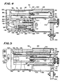
- FIG. 4 is a sectional view taken along line 4-4 of Fig. 3;
- FIG. 5 is a sectional view taken along line 5-5 of Fig. 3;
- FIG. 6 is a partial sectional view of the assembly of Fig. 1 illustrating the assembly in its static or ready mode.
- FIG. 7 is a partial sectional view of the assembly of Fig. 1 illustrating the assembly when a screw is being driven into a workpiece;
- FIG 8 is a partial sectional view of the assembly of Fig. 1 illustrating the assembly when another screw is being incrementally advanced into the nose assembly;
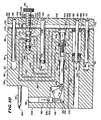
- FIG. 9 is a schematic diagram of the air circuitry for the feeder and driver mechanism portion of the assembly of Fig. 1 in a static or ready mode;
- FIG. 10 is a schematic diagram of the air circuitry for the feeder and driver mechanism portion of the assembly of Fig. 1 in a fire mode;
- FIG. 11 is a schematic diagram of the air circuitry for the feeder and driver mechanism portion of the assembly of Fig. 1 during a first portion of a return mode of the assembly; and
- FIG. 12 is a schematic diagram of the air circuitry for the feeder and driver mechanism portion of the assembly of Fig. 1 during the second portion of the return mode of the assembly.
- Referring now to the drawings, therein is disclosed a fastener driving assembly including a
fastener driving tool 20 having attached thereto a fastener feeder assembly which is generally designated as 22 and which includes adriver mechanism 36. The feeder anddriver assembly 22 further includes amagazine assembly 24 in which is housed afastener strip 26 comprised of acarrier member 28 and a plurality offasteners 30. Thefastener strip 26 is fed into anose assembly 32 of the feeder anddriver assembly 22 wherein one of thefasteners 30, such as a fastener 30a (Fig. 6), is positioned so that it can be driven into a workpiece (not shown), such as a wall panel or the like. The fastener 30a is driven into the workpiece by a driver member orbit 34 which is rotated by thefastener driving tool 20. The pneumatically operated feeder anddriver mechanism 36 forming a part of the feeder anddriver assembly 22 is attached to afront end 38 of thefastener driving tool 20 and has thenose assembly 32 mounted thereon. - As will be described in more detail hereinafter, the feeder and
driver assembly 22 is normally in a standby or static mode as illustrated in FIG. 6 of the drawings with a fastener 30a disposed in and projecting from thenose assembly 32 so as to be in a position to be driven into a workpiece. Upon the actuation of atrigger 40 of thefastener driving tool 20, thebit 34 is rotated and an operator of thetool 20 pushes thefastener driving tool 20 towards the workpiece so that the fastener 30a is forced to the left as illustrated in FIG. 7 of the drawings and is driven into a workpiece. Once the fastener 30a is inserted into the workpiece to a proper depth as determined by anadjustable stop screw 42, the feeder anddriver mechanism 36 moves thefastener driving tool 20 and thereby thebit 34 to the right as viewed in FIG. 1 during a fire mode and a first portion of a return mode of the feeder anddriver assembly 22. As a result, thebit 34 is returned to the position illustrated in FIG. 8 of the drawings. During a second portion of the return mode, thefastener strip 26 is incrementally advanced so that the next one of thefasteners 30, such asfastener 30b, is positioned in thenose assembly 32 as illustrated in FIG. 8 of the drawings. Thereafter, the feeder anddriver mechanism 36 moves thefastener driving tool 20 and thereby thebit 34 toward thefastener 30b whereby thefastener 30b is removed from thefastener strip 26 and advanced to a position illustrated in FIG. 6 with respect to the fastener 30a. The feeder anddriver assembly 22 is again in its static or ready mode so that thefastener 30b can be driven into a workpiece. - The
fastener driving tool 20 shown in FIG. 1 is a pneumatic power screwdriver and is adapted to drive fasteners, such as thefasteners 30, which in the disclosed embodiment are screws, into drywall panels and the metal or wood studs onto which such panels are mounted. Thefastener driving tool 20 includes ahousing 44 from which extends ahandle portion 46. Air from a pressurized source of air, such as a compressor, is supplied to a pneumatically operated motor (not shown) located in thehousing 44 and enables the motor to provide a rotary motion to a bit holder 48 through a clutch 50 when thetrigger 40 is depressed. While the disclosedfastener driving tool 20 is pneumatically operated, standard electric screwdrivers can be used as the driving tool in the same manner as the disclosed pneumatically operatedscrewdriver 20. - The
front portion 38 of thefastener driving tool 20 is secured to amounting block 52 forming a part of the feeder anddriver mechanism 36, which mountingblock 52 has an opening 54 into which thefront end 38 of thefastener driving tool 20 can be positioned. Upon being so positioned, aretaining screw 56 compresses the opening 54 so as to hold thefront end 38 of thefastener driving tool 20 in the opening 54. - The feeder and
driver mechanism 36 also has acylinder housing 58 in which is disposed pneumatic circuitry for controlling the operation of the feeder anddriver assembly 22. As can be best seen in FIGS. 4 and 5 of the drawings, thecylinder housing 58 includesguide cylinders guide rod 64 is movably mounted within thecylinder 60 by abearing 66 and is attached to themounting block 52 by ascrew 68. Anotherguide rod 70 is mounted to themounting block 52 by ascrew 72 and moves within thecylinder 62 in thecylinder housing 58. The guide rods 64 and 70 aid in guiding themounting block 52 as it moves relative to thecylinder housing 58 during the operation of the feeder anddriver mechanism 36. - The
cylinder housing 58 also includes anextend cylinder 74 in which is movably mounted anextend piston 76 having an 0-ring 78 to seal a portion of thecylinder 74. Theextend piston 76 is also secured to themounting block 52 by ascrew 80. During the fire mode and a portion of the return mode, theextend piston 76 causes themounting block 52 to move to the position shown in FIGS. 4 and 5. - The feeder and
driver mechanism 36 includes aretract rod 82 which is secured to themounting block 52 by ascrew 84. Aretract piston 86 is movably mounted about theretract rod 82 and apiston seal 88 forms a seal about therod 82. Afastener 90 attached to the end of theretract rod 82 forces theretract piston 86 to move to the right as viewed in FIG. 5 as theretract rod 82 moves in that direction. Theretract piston 86 travels within aretract cylinder 92 within thecylinder housing 58. The retractrod 82 pulls the mountingblock 52 to its static position during the second portion of the return mode. - A fastener
strip feeder mechanism 94 is disposed within thecylinder housing 58. Thefeeder mechanism 94 includes apawl cylinder 96 which extends vertically in thecylinder housing 58 and in which is movably mounted apawl piston 98. Afeed pawl 100 is mounted within thepawl piston 98. The movement of thepiston 98 within thepawl cylinder 96 is controlled by afeed piston 102 which is movably mounted within afeed cylinder 104. Achain link 106 is secured to thefeed piston 102 by afeed pin 108 and afastener 110. Thechain link 106 is attached to afeed pivot plate 112 which pivots on apivot 114 within acavity 116 in thecylinder housing 58. Thepivot plate 112 is attached to thepawl piston 98 by anotherchain link 118. Since thefeed piston 102 is secured to thepawl piston 98 by means of the chain links 106 and 118 and thepivot plate 112, movement of thepiston 102 from left to right in FIG. 4 translates into an up and down motion of thepiston 98 within thefeed cylinder 96. As a result, thecylinder housing 58 occupies a minimum amount of space between itsfront end 120 and itsrear end 122 such that the entire length of the feeder anddriver assembly 22 is minimized. - The
cylinder housing 58 also houses astop valve 124 disposed within astop valve cylinder 126. Thestop valve 124 is actuated by thestop screw 42 and controls the extent to which the mountingblock 52 moves towards thefront end 120 of thecylinder housing 58 while one of thefasteners 30 is being driven into a workpiece. - The
cylinder housing 58 in addition has achannel 128 through which thedriver bit 34 extends (FIG. 5). Thedriver bit 34 is held in the bit holder 48. Aspring 130 is disposed about the bit holder 48 between thecylinder housing 58 and the mountingblock 52. Thespring 130 is compressed as the mountingblock 52 is moved towards thefront end 120 of thecylinder housing 58 during the installation of one of thefasteners 30 and assists in returning the mountingblock 52 to the position shown in FIGS. 4 and 5 of the drawings during the fire mode and the first portion of the return mode. - A
cover plate 132 is secured to therear end 122 of thecylinder housing 58 byfasteners driver assembly 22 to therods pistons driver assembly 22 includes aguard 138 which is attached to the mountingblock 52 byscrews cylinder housing 58 when the mountingblock 52 moves relative to thecylinder housing 58 during the operation of the feeder anddriver assembly 22. - The
magazine assembly 24 is maintained relative to thedriving tool 20 by securing it to the mountingblock 52 by means of a downwardly projectingleg 144 which is secured to the mountingblock 52 by afastener 146. Theleg 144 is attached to asocket 148 projecting from ahousing 150 of themagazine assembly 24. Thehousing 150 preferably is formed of a relatively lightweight, yet strong material such as a suitable plastic or the like. Thehousing 150 is generally circular in outline so that it can receive thefastener strip 26 when it is rolled into a coil. In this connection, a lowerperipheral wall 152 of thehousing 150 may be swung about ahinge 154 and is latched in a closed position by alatch assembly 156. When thelatch 156 is released, thedoor 152 can be swung about thehinge 154 so that the inner part of thehousing 150 is accessible and can be filled with acoiled fastener strip 26. When thedoor 152 is again secured in its closed position as shown in FIG. 1 of the drawings, a portion of thefastener strip 26 is fed out of thehousing 150 to thenose assembly 32. The portion of thefastener strip 26 extending between thehousing 150 and thenose assembly 32 is twisted through a substantial angle so that there is no interference between thefastener strip 26 and a workpiece and thefastener strip 26 can flex as the drivingtool 20 and themagazine assembly 24 moves relative to thenose assembly 32. - As illustrated in connection with
fasteners fastener 30 includes ashank portion 158, at least a portion of which is threaded, atip 160 at the entry end of theshank portion 158 and ahead 162 at the opposite end of theshank 158. Thehead 162 is provided with a drive slot structure which is complementary to atip portion 164 of thedriver bit 34. When thetip portion 164 of thebit 34 is inserted into the complementary drive slot of thehead 162, the rotation of thedriver bit 34 causes thefastener 30 to be rotated in accordance with known practices. - The
fastener strip 26 is of the type disclosed in United States Patent No. 3,885,669, assigned to the Applicants of the present application. Thefastener strip 26 includes thecarrier member 28 which is in the form of an elongated strip of flexible plastic material. Thecarrier member 28 is continuous throughout the length of thefastener strip 26 and, as illustrated in connection with thefastener 30c in Fig. 1, includes atab 166 which extends from one side of thecarrier strip 28 and which is designed to receive thefastener 30c in a slot located in thetab 166 such that thefastener 30c is frictionally retained therein with theshank portion 158 of thefastener 30c extending generally parallel to the plane of thecarrier member 28. Thefastener strip 26 can be provided with a tab extending from the other end of thecarrier member 28 in order that thefasteners 30 are more securely affixed to thefastener strip 26. Thecarrier member 28 also is provided with a series ofopenings 168, one of which openings is longitudinally placed along thecarrier member 28 between each of thetabs 166. Theopenings 168 are adapted to receive thefeed pawl 100 in order for thefastener strip 26 to be incrementally advanced during the operation of the feeder anddriver assembly 22. - As previously indicated, the feeder and
driver mechanism 36 which forms a part of the feeder anddriver assembly 22 is a pneumatically operated mechanism. Pressurized air from an air reservoir, such as a compressor or the like, is supplied to aport 170 on the lower portion of thecylinder housing 58 via an appropriate hose or the like (not shown). The operation of the pneumatically operated feeder anddriver mechanism 36 will become more apparent with reference to FIGS. 9-12 which disclose in schematic form the pneumatic circuitry for the feeder anddriver mechanism 36 during various modes or phases of the operation of the feeder anddriver assembly 22. - More specifically, and with reference to FIG. 9 of the drawings, the feeder and
driver assembly 22 is shown therein in its static or ready mode so that one of the fasteners, such as the fastener 30a shown in FIG. 6, is ready for being driven into a workpiece. In this regard, the fastener 30a is held in anose chuck 172 consisting ofjaws - The
jaws shank 158 extending out from anose guard 178. When the feeder anddriver assembly 22 is in the static mode disclosed in FIGS. 6 and 9 of the drawings, thebit 34 has itstip portion 164 inserted into thehead 162 of the fastener 30a. Advantageously, since the top 160 of the fastener 30a extends out from the workpiece engaging surface of thenose guard 178 prior to being driven into a workpiece, the fastener 30a may be positioned within a pilot hole in the workpiece into which it is to be driven or against the workpiece, if no pilot hole is formed therein, prior to the fastener 30a being rotated and driven by thebit 34. It is noted that when the fastener 30a has been positioned as shown in FIG. 6, the fastener 30a has been removed from thefastener strip 26 as will be discussed in more detail below. - When the feeder and driven
assembly 22 is in its static mode as illustrated schematically in FIG. 9, reservoir air (i.e., pressurized air) is supplied through anair duct 180 to the portion of thecylinder 104 between an O-ring 182 sealing thecylinder 104 and 0-ring 184 on thefeed piston 102. The reservoir air is also supplied through aduct 186 to the portion of thecylinder 126 between O-rings stop valve 124 and from there through anotherduct 192 to the portion of thefeed cylinder 104 between an O-ring 194 on thefeed piston 102 and an 0-ring 195 which seals thecylinder 104 along thecover plate 132. That portion of thefeed cylinder 104 is connected via aduct 196 to the retractcylinder 92 so that reservoir air is supplied to the retractcylinder 92 between thepiston seal 88 and the retractpiston 86. - Air vents 198, 200, and 202 are provided in the
cylinder housing 58 to connect various portions of the pneumatic circuitry to atmosphere. In the static mode illustrated in FIG. 9, theair vent 198 vents that portion of thestop valve cylinder 126 between the 0-ring 190 and an 0-ring 204 to atmosphere. Since that portion of thestop valve cylinder 126 between the O-rings cylinder 74 by aduct 206, the portion of the extendcylinder 74 to the left, as viewed in FIG. 9, of the O-ring 78 on the extendpiston 76 is at atmospheric pressure. Theair vent 200 connects the portion of thestop valve cylinder 126 to the left, as viewed in FIG. 9, of the 0-ring 188 to atmosphere. Aduct 208 connects that portion of thestop valve cylinder 126 and therefore thevent 200 to the portion of the extendcylinder 74 to the right of the O-ring 78. Consequently, the entire extendpiston cylinder 74 is at atmospheric pressure. Theair vent 202 is coupled to thefeed piston cylinder 104 between the O-rings piston cylinder 104 being maintained at atmospheric pressure. - In the static mode, the retract
rod 82 positions the mountingblock 52 as illustrated in FIG. 9 of the drawings due to the fact that reservoir air supplied to thecylinder 92 forces the retractpiston 86 against aspacer 210. In addition, thefeed piston 102 positions thepawl piston 98 and consequently thefeed pawl 100 in the position shown in FIG. 9 such that one of thefasteners 30 will be in alignment with thedriver bit 34. Thefeed piston 102 is placed in this position due to the fact that reservoir air supplied to the larger diameter of thefeed piston 102 between the O-rings feed piston 102 between the O-rings cylinder 74 is vented to atmosphere, the extendpiston 76 is allowed to move within thecylinder 74 as the mountingblock 52 is moved to the left in FIG. 9 by the retractpiston 82. Thestop valve 124 is in its ready mode as shown in FIG. 9 due to the presence of reservoir air between the O-rings - When the feeder and
driver assembly 22 is in its static mode, an operator can drive a fastener, such as the fastener 30a shown in FIG. 6, into a workpiece. This is accomplished by the operator actuating thetrigger 40 so that thefastener driver tool 20 rotates the bit holder 48 which in turn causes thedriver bit 34 to rotate. The operator then pushes against thehandle 46 of thefastener driving tool 22 causing the mountingblock 52 to move toward the workpiece. This movement of the mountingblock 52 forces the bit holder 48 and thebit 34 to push against the fastener 30a and the fastener 30a is thereby installed into the workpiece. During this process, the fastener 30a forces open thejaws nose chuck 172 as illustrated in FIG. 7 of the drawings. Once the fastener 30a has been driven into the workpiece an appropriate distance, anend 212 of thestop screw 42 engages astem 214 of thestop valve 24 projecting through thecover plate 132. As a result, thestop valve 24 is moved to the position shown in FIG. 10 of the drawings initiating what can be termed the fire mode of the feeder anddriver assembly 22. - The
stop screw 42 can be adjusted relative to the mountingblock 52 and locked in place by alock nut 216. Consequently, thestop valve 124 acts as a depth control to determine the depth to which one of thefasteners 30 will be driven into a workpiece. More specifically, the location of the mountingblock 52 when the fire mode is initiated as illustrated in FIG. 10 of the drawings determines the extent to which thebit 34 has driven a fastener, such as the fastener 30a in FIG. 7, out from thenose assembly 32 into a workpiece. If thestop screw 42 is adjusted so that theend 212 of thestop screw 42 is further to the left as viewed in FIG. 9, theend 212 will engage thestem 214 when the mountingblock 52 is further to the right as viewed in FIG. 9. In this event, thefasteners 30 being driven into a workpiece will not be driven into the workpiece as deep as when thestop screw 42 is adjusted so that thetip 212 of thestop screw 42 is further to the right as viewed in FIG. 9. - When the
stop valve 124 is moved towards the position shown in FIG. 10 of the drawing, the O-ring 188 passes theair vent 200 such that theduct 192 is vented to atmosphere resulting in the venting to atmosphere of the portion of thefeed cylinder 104 between the O-ring 194 and thepiston seal 195. Since reservoir air is still supplied through theduct 180 to thefeed piston 104 between the O-rings feed piston 102 will move in the direction indicated by the arrows in FIG. 10 of the drawings. This movement of thefeed piston 102 causes thefeed pivot plate 112 to pivot about thepivot 114 pulling, via thechain link 118, thepawl piston 98 downwardly, as viewed in FIG. 10, in thefeed cylinder 96. When thepawl piston 98 moves in this manner, thefeed pawl 100 moves downwardly as viewed in FIGS. 1 and 10 along thecarrier member 28 of thefastener strip 26 that is held against thefeed pawl 100 in thenose assembly 32. However, since thefeed pawl 100 has acam surface 218 which permits thepawl 100 to slip past theopening 168 in thecarrier member 28 when thefeed piston 98 is moved as illustrated in FIG. 10, thefeed pawl 100 does not move thefastener strip 26. - As the
feed piston 102 moves to the right as viewed in FIG. 10, the O-ring 194 passes theair duct 196 so that theair duct 196 becomes vented to atmosphere because it is now connected to theair vent 202. Consequently, the retractcylinder 92 between the retractpiston 86 and thepiston seal 88 is placed at atmospheric pressure so that the retractpiston 86 can be moved towards thepiston seal 88. The movement of thestop valve 124 also results in the movement of the 0-ring 190 past theduct 186 so that reservoir air is now supplied to thestop valve cylinder 126 between the O-rings duct 206 to the extendcylinder 74 to the left of 0-ring 78 as viewed in FIG. 10. Since the extendcylinder 74 to the right of the O-ring 78 is maintained at atmospheric pressure, via an opening in thecover plate 132 about the extendcylinder 74, the extendpiston 76 is forced to the right as viewed in FIG. 10 of the drawings. The movement of the extendpiston 76 in this manner forces the mountingblock 52 to the right as viewed in FIG. 10. This movement of the mountingblock 52 is guided by theguide rods - The mounting
block 52 continues to move to the right. FIG. 11 of the drawings schematically illustrates the feeder anddriver mechanism 36 at a point in time during what can be termed a first portion of the return mode of the feeder anddriver assembly 22. During this portion of the return mode, reservoir air continues to be supplied to the extendcylinder 74 forcing the extendpiston 76 further to the right as viewed in FIG. 11. As the mountingblock 52 moves to the right as viewed in FIG. 11, thefastener 90 on the retractrod 82 engages the retractpiston 86 and moves it away from thespacer 210 so as to move it toward thepiston seal 88 as illustrated in FIG. 11 of the drawings. During this portion of the return mode of the feeder anddriver assembly 22, thefeed piston 102 is maintained in the position shown in FIG. 11 so that thefeed pawl 100 is in its lowered position illustrated in FIG. 11 and is in alignment with the next one of theopenings 168 in thecarrier member 28 of thefastener strip 26 so that it will be in a position to incrementally advance thecarrier member 28 when the feeder anddriver assembly 22 enters the second portion of its return mode. Thestop valve 124 remains in its depressed or actuated position due to the fact that reservoir air continues to be supplied to thestop valve cylinder 126 between O-rings stop valve cylinder 126 are maintained at atmospheric pressure. It is noted that at the point in time during the return mode illustrated in FIG. 11, the 0-ring 78 on the extendpiston 76 is still to the left of theduct 208. As the extendpiston 76 is forced further to the right as viewed in FIG. 11, the 0-ring 78 will move past theduct 208 resulting in the feeder anddriver assembly 22 transferring into the second portion of its return mode. - As the extend
piston 76 moves to the right as viewed in FIGS. 11 and 12 of the drawings and the O-ring 78 passes theduct 208, reservoir air in the extendcylinder 74 is communicated viaduct 208 to the portion of thestop valve cylinder 126 to the left of O-ring 188. Thestop valve 124 is thereby forced toward the right in FIG. 12 to its ready position illustrated in FIG. 12. When thestop valve 124 has been so moved, the portion of thestop valve cylinder 126 to the left of O-ring 188 is vented to atmosphere because it is now in communication with theair vent 200. In addition, the portion of the extendcylinder 74 to the left of the O-ring 78 is also vented to atmosphere because it is coupled to theair vent 200 through the lefthand portion of thestop valve cylinder 126 and theduct 208. Since no reservoir air is supplied to the extendcylinder 74, the extendpiston 76 will cease moving to the right as viewed in FIG. 12 such that the mountingblock 52 no longer will be moved in that direction. At this point in time, thebit holder 130 has also been retracted to the right in FIG. 12 so that thebit 34 is positioned as illustrated in FIG. 8 of the drawings. - Once the
stop valve 124 is returned to its ready position illustrated in FIG. 12, reservoir air that is being supplied via theduct 186 to thestop valve cylinder 126 between the 0-ring duct 192 because theduct 186 is now in communication with the portion of thestop valve cylinder 126 between the O-rings feed piston cylinder 104 between the O-rings feed piston 102 has a larger diameter in the area of the O-ring 194 as compared to the diameter of the feed piston between the O-rings feed piston 104 is forced to move to the left as viewed in FIG. 12 of the drawings. This results in the movement of thefeed assembly 94 such that thepivot plate 112 is pivoted about thepivot 114 as shown by the arrow on thepivot plate 112 in FIG. 12. Thefeed piston 98 moves upwardly in thefeed cylinder 96 so thatfeed pawl 100 also is moved upwardly in FIG. 12 to the position shown in FIG. 12. The movement of thefeed pawl 100 in this manner results in thecam surface 218 engaging one of theopenings 168 in thecarrier member 28 of thefastener strip 26 and thefastener strip 26 is incrementally advanced upwardly as viewed in FIG. 1 of the drawings. The incremental advance of thefastener strip 26 in this manner results in the next one of thefasteners 30 to be positioned in alignment with thebit 34 as illustrated in FIG. 8 of the drawing. - As the
feed piston 104 is moved in this manner, the 0-ring 194 passes theduct 196 and reservoir air is supplied from thefeed cylinder 104 through theduct 196 to the retractcylinder 92 between the retractpiston 86 and thepiston seal 88. The supplying of reservoir air to the retractcylinder 92 in this manner forces the retractpiston 86 to move to the left as viewed in FIG. 12 and the retractpiston 86 engages thefastener 90 forcing the retractrod 82 to also move towards the left as viewed in FIG. 12 of the drawing. Movement of the retractrod 82 forces the mountingblock 52 to also move to the left as viewed in FIG. 12. - The movement of the mounting
block 52 is not inhibited by the extendpiston 76 because the extendcylinder 74 is maintained at atmospheric pressure since theair vent 198 is now coupled to the lefthand portion of the extendcylinder 74 through theduct 206. As the mountingblock 52 moves to the left in FIG. 12 toward its static or ready position as illustrated in FIG. 9 of the- drawings, thebit holder 130 and therefore thebit 34 are moved toward thefastener 30b as shown in FIG. 8 which has been positioned in thenose assembly 32 in alignment with thebit 34 by the incremental advance of thecarrier member 28 of thefastener strip 26 due to the movement of thefeed pawl 100. - The mounting
block 52 will proceed to move toward therear end 122 of thecylinder housing 58 due to the continued supplying of reservoir air to the retractcylinder 92 between the retractpiston 86 and thepiston seal 88. The mountingblock 52 will come to its static or ready position as illustrated in FIG. 9 when the retractpiston 86 engages thespacer 210. Prior to the mountingblock 52 being positioned as illustrated in FIG. 9 of the drawings, thetip 164 of thebit 34 will engage thehead 162 of thefastener 30b forcing thefastener 30b be removed from the slot in thetab 166 on thecarrier member 28 in which thefastener 30b is held. Thefastener 30b is then forced between thenose jaws bit 34 and thefastener 30b will be positioned as shown in FIG. 6 when the mountingblock 52 is positioned as shown in FIG. 9 with the retractpiston 86 against thespacer 210. At this point in the operation of the feeder anddriver assembly 22, the feeder anddriver assembly 22 is now in its static or ready position to again be actuated by an operator installing thenext screw 30b into a workpiece. - Since the
fastener driving tool 20 and the feeder anddriver mechanism 36 can be operated by pressurized air supplied by a portable compressor or the like, the feeder anddriver assembly 22 can be utilized at a construction site or any other location where a source of pressurized air is available. Moreover, the feeder anddriver assembly 22 can be made relatively lightweight and not cumbersome as compared to a mechanism which would require an electric motor or the like to operate the feeder and driver mechanism.
Claims (5)
Applications Claiming Priority (2)
| Application Number | Priority Date | Filing Date | Title |
|---|---|---|---|
| US73349285A | 1985-05-13 | 1985-05-13 | |
| US733492 | 1991-07-22 |
Publications (2)
| Publication Number | Publication Date |
|---|---|
| EP0202103A1 EP0202103A1 (en) | 1986-11-20 |
| EP0202103B1 true EP0202103B1 (en) | 1991-01-23 |
Family
ID=24947829
Family Applications (1)
| Application Number | Title | Priority Date | Filing Date |
|---|---|---|---|
| EP86303617A Expired - Lifetime EP0202103B1 (en) | 1985-05-13 | 1986-05-13 | Fastener feeder assembly for use with fastener driver apparatus |
Country Status (6)
| Country | Link |
|---|---|
| EP (1) | EP0202103B1 (en) |
| JP (1) | JPS61260983A (en) |
| AU (1) | AU585609B2 (en) |
| CA (1) | CA1270601A (en) |
| DE (1) | DE3677049D1 (en) |
| ZA (1) | ZA863487B (en) |
Families Citing this family (4)
| Publication number | Priority date | Publication date | Assignee | Title |
|---|---|---|---|---|
| FR2791862B1 (en) | 1999-03-31 | 2001-06-29 | Legrand Sa | DISTRIBUTOR BOX FOR WIRING ACCESSORIES, AND CORRESPONDING CHARGER |
| JP4534623B2 (en) * | 2004-06-23 | 2010-09-01 | マックス株式会社 | Nose top guide device for fastener-driven tools |
| US20240139893A1 (en) * | 2022-10-28 | 2024-05-02 | House of Design LLC | Auto feed fastener tool |
| WO2025248961A1 (en) * | 2024-05-31 | 2025-12-04 | 国立大学法人東北大学 | Driving device for screw member |
Family Cites Families (4)
| Publication number | Priority date | Publication date | Assignee | Title |
|---|---|---|---|---|
| SE326141B (en) * | 1968-07-08 | 1970-07-13 | Atlas Copco Ab | |
| DE2641828C3 (en) * | 1976-09-17 | 1981-03-26 | Karl M. Reich Maschinenfabrik GmbH, 72622 Nürtingen | Driver for screws or the like connected to form a strip. |
| AU506486B2 (en) * | 1977-07-22 | 1980-01-03 | Heifer, H | Screwdriving device |
| JPS59124579A (en) * | 1982-12-27 | 1984-07-18 | 室金属工業株式会社 | Continuous screw clamping machine |
-
1986
- 1986-05-05 CA CA000508384A patent/CA1270601A/en not_active Expired - Fee Related
- 1986-05-08 AU AU57279/86A patent/AU585609B2/en not_active Ceased
- 1986-05-12 ZA ZA863487A patent/ZA863487B/en unknown
- 1986-05-13 DE DE8686303617T patent/DE3677049D1/en not_active Expired - Fee Related
- 1986-05-13 EP EP86303617A patent/EP0202103B1/en not_active Expired - Lifetime
- 1986-05-13 JP JP61109333A patent/JPS61260983A/en active Pending
Also Published As
| Publication number | Publication date |
|---|---|
| EP0202103A1 (en) | 1986-11-20 |
| ZA863487B (en) | 1986-12-30 |
| AU585609B2 (en) | 1989-06-22 |
| CA1270601A (en) | 1990-06-26 |
| JPS61260983A (en) | 1986-11-19 |
| AU5727986A (en) | 1986-11-20 |
| DE3677049D1 (en) | 1991-02-28 |
Similar Documents
| Publication | Publication Date | Title |
|---|---|---|
| US4774863A (en) | Fastener feeder and driver apparatus | |
| US7866521B2 (en) | Magazine for wired-collated fasteners with automatic loading | |
| US5327639A (en) | Automatic rivet feed apparatus | |
| US7137186B2 (en) | Magazine for wired-collated fasteners with automatic loading | |
| US3543987A (en) | Fastener driving tool | |
| US8051919B2 (en) | Fastening tool with automatic feeding of wire-collated fasteners | |
| CA2709532C (en) | Pneumatic fastener driving tool | |
| AU2007342410B2 (en) | Cordless fastener tool with fastener driving and rotating functions | |
| CA2104490A1 (en) | Positioning Mechanism for Powered Fastener-Driving Tool | |
| CA2189027C (en) | Screw strip with overlapping washers, and method and apparatus for installation | |
| US3891014A (en) | Screw magazine mechanism for power screwdriver | |
| JP3793272B2 (en) | Screw driving method and apparatus | |
| EP1755836B1 (en) | Fastener magazine for a driving tool | |
| GB2095601A (en) | Mechanism for feeding screws | |
| EP0034679B1 (en) | Barrel assembly for a fastener driving tool | |
| US3741455A (en) | Fastener driving tool | |
| EP0202103A1 (en) | Fastener feeder assembly for use with fastener driver apparatus | |
| US2801417A (en) | Magazine closure for stapling implements | |
| US2818893A (en) | Power operated magazine fed screw driver | |
| US4657166A (en) | Pneumatically operated nailing machine | |
| EP0102412B1 (en) | Drilling device, particularly for removing a spot-welded portion | |
| GB1430097A (en) | Fastener feed for power tools | |
| JP2691361B2 (en) | Fixing tool driving tool depth adjustment device | |
| JP2004074316A (en) | Fastener driving position marking device for fastener driver | |
| GB2178356A (en) | Fastener driving apparatus and magazine |
Legal Events
| Date | Code | Title | Description |
|---|---|---|---|
| PUAI | Public reference made under article 153(3) epc to a published international application that has entered the european phase |
Free format text: ORIGINAL CODE: 0009012 |
|
| AK | Designated contracting states |
Kind code of ref document: A1 Designated state(s): DE FR GB IT NL SE |
|
| 17P | Request for examination filed |
Effective date: 19870507 |
|
| 17Q | First examination report despatched |
Effective date: 19880719 |
|
| ITF | It: translation for a ep patent filed | ||
| GRAA | (expected) grant |
Free format text: ORIGINAL CODE: 0009210 |
|
| AK | Designated contracting states |
Kind code of ref document: B1 Designated state(s): DE FR GB IT NL SE |
|
| REF | Corresponds to: |
Ref document number: 3677049 Country of ref document: DE Date of ref document: 19910228 |
|
| ET | Fr: translation filed | ||
| PG25 | Lapsed in a contracting state [announced via postgrant information from national office to epo] |
Ref country code: GB Effective date: 19910513 |
|
| PG25 | Lapsed in a contracting state [announced via postgrant information from national office to epo] |
Ref country code: SE Effective date: 19910514 |
|
| PLBE | No opposition filed within time limit |
Free format text: ORIGINAL CODE: 0009261 |
|
| STAA | Information on the status of an ep patent application or granted ep patent |
Free format text: STATUS: NO OPPOSITION FILED WITHIN TIME LIMIT |
|
| PG25 | Lapsed in a contracting state [announced via postgrant information from national office to epo] |
Ref country code: NL Effective date: 19911201 |
|
| GBPC | Gb: european patent ceased through non-payment of renewal fee | ||
| 26N | No opposition filed | ||
| NLV4 | Nl: lapsed or anulled due to non-payment of the annual fee | ||
| PG25 | Lapsed in a contracting state [announced via postgrant information from national office to epo] |
Ref country code: FR Effective date: 19920131 |
|
| PG25 | Lapsed in a contracting state [announced via postgrant information from national office to epo] |
Ref country code: DE Effective date: 19920303 |
|
| REG | Reference to a national code |
Ref country code: FR Ref legal event code: ST |
|
| EUG | Se: european patent has lapsed |
Ref document number: 86303617.4 Effective date: 19911209 |
|
| PG25 | Lapsed in a contracting state [announced via postgrant information from national office to epo] |
Ref country code: IT Free format text: LAPSE BECAUSE OF NON-PAYMENT OF DUE FEES;WARNING: LAPSES OF ITALIAN PATENTS WITH EFFECTIVE DATE BEFORE 2007 MAY HAVE OCCURRED AT ANY TIME BEFORE 2007. THE CORRECT EFFECTIVE DATE MAY BE DIFFERENT FROM THE ONE RECORDED. Effective date: 20050513 |