EP0201912B1 - An improved diffuser for centrifugal compressors and the like - Google Patents
An improved diffuser for centrifugal compressors and the like Download PDFInfo
- Publication number
- EP0201912B1 EP0201912B1 EP86106477A EP86106477A EP0201912B1 EP 0201912 B1 EP0201912 B1 EP 0201912B1 EP 86106477 A EP86106477 A EP 86106477A EP 86106477 A EP86106477 A EP 86106477A EP 0201912 B1 EP0201912 B1 EP 0201912B1
- Authority
- EP
- European Patent Office
- Prior art keywords
- diffuser
- passageway
- ribs
- impeller
- outlet
- Prior art date
- Legal status (The legal status is an assumption and is not a legal conclusion. Google has not performed a legal analysis and makes no representation as to the accuracy of the status listed.)
- Expired - Lifetime
Links
Images

Classifications
-
- F—MECHANICAL ENGINEERING; LIGHTING; HEATING; WEAPONS; BLASTING
- F04—POSITIVE - DISPLACEMENT MACHINES FOR LIQUIDS; PUMPS FOR LIQUIDS OR ELASTIC FLUIDS
- F04D—NON-POSITIVE-DISPLACEMENT PUMPS
- F04D29/00—Details, component parts, or accessories
- F04D29/40—Casings; Connections of working fluid
- F04D29/42—Casings; Connections of working fluid for radial or helico-centrifugal pumps
- F04D29/44—Fluid-guiding means, e.g. diffusers
- F04D29/441—Fluid-guiding means, e.g. diffusers especially adapted for elastic fluid pumps
- F04D29/444—Bladed diffusers
-
- F—MECHANICAL ENGINEERING; LIGHTING; HEATING; WEAPONS; BLASTING
- F05—INDEXING SCHEMES RELATING TO ENGINES OR PUMPS IN VARIOUS SUBCLASSES OF CLASSES F01-F04
- F05D—INDEXING SCHEME FOR ASPECTS RELATING TO NON-POSITIVE-DISPLACEMENT MACHINES OR ENGINES, GAS-TURBINES OR JET-PROPULSION PLANTS
- F05D2250/00—Geometry
- F05D2250/50—Inlet or outlet
- F05D2250/52—Outlet
Definitions
- This invention relates generally to centrifugal compressors. More particularly, but not by way of limitation, this invention relates to a diffuser for a centrifugal compressor that includes a plurality of ribs located in a diffuser passageway.
- vanes or ribs have been located in the diffuser passageways, as clearly shown in U.S. Patent No. 4,395,197 issued July 26, 1983 to Yoshinaga et al and in U.S. Patent No. 4,421,457 issued December 20, 1983 to Yoshinaga et al. It will be noted in those patents that ribs, as distinguished from vanes, have been located in the diffuser passageways. (Ribs do not extend entirely across the passageway. Vanes do.)
- locating the ribs in this manner can aid in increasing the flow angle adjacent to the shroud side of the diffuser and thus increases the efficiency of the compressors in which they are located.
- the primary effect of the ribs is to redirect the low angle flow immediately adjacent to them, but will not redirect the low angle flow at all positions between adjacent ribs particularly at radii near the diffuser inlet. This creates the potential for reverse flow into the impeller with resulting performance degradation.
- FIGS. 7 and 7A of the '457 patent there is also illustrated a tapered diffuser passageway that is provided with diffuser ribs.
- the tapered diffuser passageway as illustrated therein, is of uniform taper starting with the largest dimension adjacent to the impeller outlet and tapering inwardly to the diffuser outlet.
- US-A-2 836 347 discloses a diffuser using a plurality of vanes, but no ribs. The vanes extend entirely across the diffuser passageway so that a correction of a part of the flow which does not need to be corrected will occur.
- FR-A-1 127 859 discloses a compressor having a spiral shaped collection chamber.
- JP-A-5 660 899 as summarized in PATENT ABSTRACTS OF JAPAN, VOLUME 5, NUMBER 123 (M-82) (795), 8th August 1981 discloses a diffuser wherein the width of a flow passage is narrowed and a plurality of guide vanes is installed at the tapered part thus forming unform distribution of the flow at the inlet part of the diffuser.
- An object of this invention is to provide an improved diffuser for centrifugal compressors that increases the efficiency of the compressors by providing a more uniform flow through the diffuser and incorporates features that substantially reduce the buffeting, noise, and shock loading of the diffuser ribs and of the impeller blades.
- a centrifugal compressor as claimed in claim 1 is provided.
- a centrifugal compressor as claimed in claim 2 is provided.
- Preferred embodiments of the compressor are referred to in dependent claims 3 to 6.
- a centrifugal compressor as set forth in claim 9 is provided.
- a method for increasing the efficiency of a centrifugal compressor as defined in claim 7 is provided.
- a method for increasing the angle of gas passing through the diffuser passageway of a centrifugal compressor as set forth in claim 8 is provided.
- This invention then provides an improved diffuser for a centrifugal compressor that has an inner diameter sized to receive the impeller and that includes an annular diffuser passageway arranged in general radial alignment with the outlet of the impeller. More specifically, the passageway is a "pinched" passageway reducing in width at a varied rate upon progressing radially outward from an inlet to an outlet. In particular, an intermediate passageway portion is located between the inlet and the outlet and is of less axial width than the axial width of the impeller outlet.
- the invention is characterized by a plurality of circumferentially spaced ribs located in the diffuser passageway with leading edges of the ribs positioned in the intermediate portion of the passageway remote both from the outlet of the impeller and the inlet of the diffuser passageway.
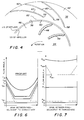
- FIG. 1 is a fragmentary cross-sectional view illustrating one prior constructed ribbed diffuser arrangement.
- FIG. 2 is a fragmentary cross-sectional view of the centrifugal compressor incorporating a diffuser that is constructed in accordance with the invention.
- FIG. 3 is an enlarged fragmentary cross-sectional view of the outer peripheral portion of the impeller and illustrating in more detail the structure of the diffuser that is constructed in accordance with the invention.
- FIG. 4 is a cross-sectional view taken generally along the line 4-4 of FIG. 3.
- FIG. 5 is a graphic representation comparing the angular flow distribution axially across the impeller outlet and the leading edges of the diffuser ribs constructed in accordance with the invention.
- FIG. 6 is a simplified, graphic representation illustrating flow angle distribution of the FIG. 1 prior art construction as taken between adjacent ribs and at various radial locations adjacent to the shroud side of the diffuser passageway.
- FIG. 7 is a view similar to FIG. 6, but illustrating the flow angle distributions taken at approximately the same radial positions in the diffuser arrangement of the present invention.
- FIG. 1 shown therein is a fragmentary view of a compressor as shown in the prior art that is designated by the reference character 10.
- the compressor 10 includes an impeller 12 that is journaled in the compressor 10.
- the impeller 12 has an outlet 14 disposed adjacent to an inlet 16 of an annular diffuser passageway 18.
- the diffuser passageway 18 is tapered from the inlet 16 to an outlet 20 thereof.
- Located in the passageway 18 is a plurality of ribs 22 that have their leading edges 24 located at the inlet 16 of the diffuser passageway 18. It will also be noted that the inlet 16 is very close to the outlet 14 of the impeller 12.
- FIG. 2 illustrates a compressor that is generally designated by the reference character 30 which is constructed in accordance with the invention.
- the compressor 30 includes a diffuser 32 and an impeller 34 that is journaled in a compressor housing 33.
- the impeller 34 includes an inlet 36 and an outlet 38 that is disposed immediately adjacent to and in radial alignment with an inlet 40 into an annular diffuser passageway 42 formed in the diffuser 32.
- the impeller 34 also includes a shroud or cover 44 and a hub 46 that are held in spaced relationship by a plurality of blades 48.
- FIGS. 3 and 4 illustrate in more detail the structural arrangement of the diffuser 30 and of the impeller 34.
- the diffuser passageway 42 includes an outlet 50 and disposed between the outlet 50 and the inlet 40 is an intermediate portion 52.
- the diffuser passageway 42 is annular in configuration and is defined by a shroud surface 54 and a hub surface 56 which are in general alignment with inner surfaces on the shroud 44 and hub 46 of the impeller 34.
- the passageway 42 is a "pinched" passageway in that the rate of reduction in passageway width (see FIG. 3) varies upon progressing from the inlet 40 thereof to the outlet 50.
- the shroud surface 54 extends from the inlet 40 of the diffuser passageway 42 to a leading edge 58 on a diffuser rib 60 and is provided with a curved or "pinched” surface 62.
- the hub surface 56 is similarly provided with a curved or "pinched” surface 64.
- the approach of the surfaces 62 and 64 toward each other is at a much greater rate than the linear taper of the passageway 42 existing downstream of the leading edge 58. From beginning to end of such surfaces, the "pinch” may be in a range of from 15% to 60% of the width of the impeller outlet 38 such that substantially over half of the total passageway pinch exists upstream of the leading edge 58.
- the surfaces 54 and 56 are illustrated as being disposed at an angle relative to each other thereby defining a tapered annular diffuser passageway 42. Manifestly, the surfaces 54 and 56 may be parallel to each other if desired.
- the location of the leading edges of vanes, as distinguished from ribs, has been traditionally defined by multiplying the outer diameter of the impeller 34 by a factor of from 1.06 to about 1.2. The factor varies depending on the operating parameters of the compressor 30. Accordingly, the location of the leading edges 58 of the ribs 60 may also be determined.
- the impeller 34 is appropriately driven by an engine or motor (not shown). Gas passing through the inlet 36 of the impeller is driven by the impeller blades 48 through the outlet 38 thereof.
- the gas impinges immediately upon the leading edge of the rib 22 so that the fluctuating pressures generated as each blade 12 passes each rib 22, create a condition for potential shock loading, and pounding to fatigue the ribs 22 and blades 12 and cause significant noise and flow disturbance, which all detrimentally impact the desired preformance of the compressor.
- the compressor 10 can be provided with only a finite number of ribs 22 in the diffuser.
- the flow angle distribution adjacent to the shroud wall and between ribs 22 of the FIG. 1 prior art arrangement varies between adjacent ribs.
- the flow angle 'a' increases upwardly on the the graphs and the right and left-hand sides of the graph represent the facing walls of adjacent ribs so that the span between rib is represented by the distance between sides of the graph.
- the lower line labelled r io represents an idealized graph of the flow angle taken between the ribs at the impeller outlet.
- the graph lines labelled r di- and r di+ are representative graphs of the flow angles taken immediately before and immediately after the leading edges of the two adjacent ribs 22.
- Lines r ii and r aa are intermediate graphs taken at selected radially outward locations and line r do is a representative graph of the flow angle at the outlet of the diffuser passage 18.
- the flow angle in the center of the area between the ribs is essentially unchanged immediately downstream of the leading edge of the ribs 22 while adjacent to each rib the flow angle is changed substantially.
- the graph droops substantially between the ribs creating the potential as diffusion occurs and pressure is increased to cause a reversal of gas flow toward the impeller, resulting in a loss of compressor performance. This effect is carried through to the diffuser outlet with a substantial droop still being clearly shown in the graph r do .
- the leading edges 58 of the ribs 60 have been retracted substantially and the impact of the pressure fluctuations on the ribs 60 and on the blades 48 is substantially reduced thereby, if not eliminated.
- the compressor 30 provides the "pinched" initial diffuser passageway to maintain the flow angle closer to the design value of flow angle to improve the efficiency of the compressor 10 while avoiding the potential damage from pressure fluctuations that is present in the compressor 10 due to the location of the leading edges 24 of the ribs 22.
- FIG. 5 illustrates, by the dash-dot line, the distribution of the gas flow angles at the leading edge 58 of the rib 60 as measured from the tangential to the impeller circumference. This flow angle distribution is to be compared with the flow angle distribution at the impeller outlet 38 which is shown by the solid line. It can be seen that the effect of the surfaces 62 and 64 is to improve the flow angle of the gas in the diffuser as compared to that exiting from the impeller.
- FIG. 7 is similar to FIG. 6 and illustrates improved idealized flow angle curves at radial locations comparable to those shown in FIG. 6, but within the diffuser passageway 42.
- the flow angle a is seen to be constant at each radius regardless of circumferential position, but increasing in magnitude as the radius increases up to the rib leading edges 58.
- R io represents the flow angle of gas exiting the impeller over a annular span on the surface 62 equal to the distance between the ribs 23 and R di represents the flow angle distribution at the diffuser inlet 40.
- R ii is an intermediate position taken at a radius equal to the radius for r ii .
- this position is located upstream of the radial positions of the leading edges 58.
- the graphs R aa- and R aa+ are taken at radial positions virtually equal to the radial position of r aa and are positions located immediately upstream and immediately downstream of the radial location of the leading edges 58 of the ribs 60. From a comparison of FIGS. 6 and 7, it is readily seen that, the flow angles in the passageway 42 of exemplary compressor 30 are increased uniformly and immediately and with less initial radial pressure gardient are combining to reduce the propensity for flow reversal.
- the ribs can be reduced in height thereby reducing the cantilever loading that pressure impulses may impose as they strike the ribs.
- the blade height reduction increases the natural frequency of ribs so as to help avoid resonance frequency problems in compressors designed with high blade passing frequencies.
- the length, that is the radial extent, of the ribs may be reduced providing less friction in the diffuser and providing some increase in compressor efficiency.
- the compressor described in detail hereinbefore incorporating a diffuser that is constructed in accordance with the invention provides a much improved flow angle distribution and reduces the buffeting of the ribs and blades to improve compressor efficiency and structural integrity.
Landscapes
- Engineering & Computer Science (AREA)
- Mechanical Engineering (AREA)
- General Engineering & Computer Science (AREA)
- Structures Of Non-Positive Displacement Pumps (AREA)
Description
- This invention relates generally to centrifugal compressors. More particularly, but not by way of limitation, this invention relates to a diffuser for a centrifugal compressor that includes a plurality of ribs located in a diffuser passageway.
- In any centrifugal compressor as the fluid flow exits the impeller, the flow distribution is distorted. Specifically, such distorted flow is characterized by a low angle (relative to a tangent to the impeller circumference) fluid flow exiting most prominently adjacent to the shroud side of the diffuser. In the past, this distorted flow has been shown to cause severe compressor preformance problems.
- In an attempt to alleviate the foregoing, vanes or ribs have been located in the diffuser passageways, as clearly shown in U.S. Patent No. 4,395,197 issued July 26, 1983 to Yoshinaga et al and in U.S. Patent No. 4,421,457 issued December 20, 1983 to Yoshinaga et al. It will be noted in those patents that ribs, as distinguished from vanes, have been located in the diffuser passageways. (Ribs do not extend entirely across the passageway. Vanes do.)
- It will also be noted in those patents that the leading edges of the ribs are located extremely close to the outlet or outer diameter of the impeller. Accordingly, such ribs are subjected to the shock loading and pounding resulting from pressure fluctuations created as the impeller blades move past the ribs. Such pressure is imposed on both the ribs and impeller blades. It is believed that such pounding may, therefore, result in fatigue of the ribs and of the blades, significant noise levels, and increased flow disturbance.
- It should also be pointed out, however, that locating the ribs in this manner can aid in increasing the flow angle adjacent to the shroud side of the diffuser and thus increases the efficiency of the compressors in which they are located. However, the primary effect of the ribs is to redirect the low angle flow immediately adjacent to them, but will not redirect the low angle flow at all positions between adjacent ribs particularly at radii near the diffuser inlet. This creates the potential for reverse flow into the impeller with resulting performance degradation.
- In FIGS. 7 and 7A of the '457 patent, there is also illustrated a tapered diffuser passageway that is provided with diffuser ribs. The tapered diffuser passageway, as illustrated therein, is of uniform taper starting with the largest dimension adjacent to the impeller outlet and tapering inwardly to the diffuser outlet.
- US-A-2 836 347 discloses a diffuser using a plurality of vanes, but no ribs. The vanes extend entirely across the diffuser passageway so that a correction of a part of the flow which does not need to be corrected will occur. FR-A-1 127 859 discloses a compressor having a spiral shaped collection chamber. JP-A-5 660 899 as summarized in PATENT ABSTRACTS OF JAPAN, VOLUME 5, NUMBER 123 (M-82) (795), 8th August 1981 discloses a diffuser wherein the width of a flow passage is narrowed and a plurality of guide vanes is installed at the tapered part thus forming unform distribution of the flow at the inlet part of the diffuser.
- An object of this invention is to provide an improved diffuser for centrifugal compressors that increases the efficiency of the compressors by providing a more uniform flow through the diffuser and incorporates features that substantially reduce the buffeting, noise, and shock loading of the diffuser ribs and of the impeller blades.
- In one aspect of the invention a centrifugal compressor as claimed in claim 1 is provided. In another aspect of the invention a centrifugal compressor as claimed in claim 2 is provided. Preferred embodiments of the compressor are referred to in dependent claims 3 to 6. In another aspect of the invention a centrifugal compressor as set forth in claim 9 is provided. In a further aspect of the invention a method for increasing the efficiency of a centrifugal compressor as defined in claim 7 is provided. In a still further aspect of the invention a method for increasing the angle of gas passing through the diffuser passageway of a centrifugal compressor as set forth in claim 8 is provided.
- This invention then provides an improved diffuser for a centrifugal compressor that has an inner diameter sized to receive the impeller and that includes an annular diffuser passageway arranged in general radial alignment with the outlet of the impeller. More specifically, the passageway is a "pinched" passageway reducing in width at a varied rate upon progressing radially outward from an inlet to an outlet. In particular, an intermediate passageway portion is located between the inlet and the outlet and is of less axial width than the axial width of the impeller outlet. In a more detailed aspect, the invention is characterized by a plurality of circumferentially spaced ribs located in the diffuser passageway with leading edges of the ribs positioned in the intermediate portion of the passageway remote both from the outlet of the impeller and the inlet of the diffuser passageway.
- The foregoing and additional objects and advantages of the invention will become more apparent as the following detailed description is read in conjunction with the accompanying drawing wherein like reference characters denote like parts in all views and wherein:
FIG. 1 is a fragmentary cross-sectional view illustrating one prior constructed ribbed diffuser arrangement. - FIG. 2 is a fragmentary cross-sectional view of the centrifugal compressor incorporating a diffuser that is constructed in accordance with the invention.
- FIG. 3 is an enlarged fragmentary cross-sectional view of the outer peripheral portion of the impeller and illustrating in more detail the structure of the diffuser that is constructed in accordance with the invention.
- FIG. 4 is a cross-sectional view taken generally along the line 4-4 of FIG. 3.
- FIG. 5 is a graphic representation comparing the angular flow distribution axially across the impeller outlet and the leading edges of the diffuser ribs constructed in accordance with the invention.
- FIG. 6 is a simplified, graphic representation illustrating flow angle distribution of the FIG. 1 prior art construction as taken between adjacent ribs and at various radial locations adjacent to the shroud side of the diffuser passageway.
- FIG. 7 is a view similar to FIG. 6, but illustrating the flow angle distributions taken at approximately the same radial positions in the diffuser arrangement of the present invention.
- Referring to the drawing, and to FIG. 1 in particular, shown therein is a fragmentary view of a compressor as shown in the prior art that is designated by the
reference character 10. Thecompressor 10 includes animpeller 12 that is journaled in thecompressor 10. Theimpeller 12 has anoutlet 14 disposed adjacent to aninlet 16 of anannular diffuser passageway 18. It will be noted that thediffuser passageway 18 is tapered from theinlet 16 to anoutlet 20 thereof. Located in thepassageway 18 is a plurality ofribs 22 that have their leadingedges 24 located at theinlet 16 of thediffuser passageway 18. It will also be noted that theinlet 16 is very close to theoutlet 14 of theimpeller 12. - The fragmentary cross-sectional view of FIG. 2 illustrates a compressor that is generally designated by the
reference character 30 which is constructed in accordance with the invention. Thecompressor 30 includes adiffuser 32 and animpeller 34 that is journaled in acompressor housing 33. Theimpeller 34 includes aninlet 36 and anoutlet 38 that is disposed immediately adjacent to and in radial alignment with aninlet 40 into anannular diffuser passageway 42 formed in thediffuser 32. Theimpeller 34 also includes a shroud orcover 44 and ahub 46 that are held in spaced relationship by a plurality ofblades 48. - The enlarged fragmentary views of FIGS. 3 and 4 illustrate in more detail the structural arrangement of the
diffuser 30 and of theimpeller 34. In addition to theinlet 40, thediffuser passageway 42 includes anoutlet 50 and disposed between theoutlet 50 and theinlet 40 is anintermediate portion 52. Thediffuser passageway 42 is annular in configuration and is defined by ashroud surface 54 and ahub surface 56 which are in general alignment with inner surfaces on theshroud 44 andhub 46 of theimpeller 34. - In particular the
passageway 42 is a "pinched" passageway in that the rate of reduction in passageway width (see FIG. 3) varies upon progressing from theinlet 40 thereof to theoutlet 50. Theshroud surface 54 extends from theinlet 40 of thediffuser passageway 42 to a leadingedge 58 on adiffuser rib 60 and is provided with a curved or "pinched"surface 62. Thehub surface 56 is similarly provided with a curved or "pinched"surface 64. The approach of thesurfaces passageway 42 existing downstream of the leadingedge 58. From beginning to end of such surfaces, the "pinch" may be in a range of from 15% to 60% of the width of theimpeller outlet 38 such that substantially over half of the total passageway pinch exists upstream of the leadingedge 58. - The
surfaces annular diffuser passageway 42. Manifestly, thesurfaces - The location of the leading edges of vanes, as distinguished from ribs, has been traditionally defined by multiplying the outer diameter of the
impeller 34 by a factor of from 1.06 to about 1.2. The factor varies depending on the operating parameters of thecompressor 30. Accordingly, the location of theleading edges 58 of theribs 60 may also be determined. - In operation, the
impeller 34 is appropriately driven by an engine or motor (not shown). Gas passing through theinlet 36 of the impeller is driven by theimpeller blades 48 through theoutlet 38 thereof. In the case of thecompressor 10 shown in FIG. 1, the gas impinges immediately upon the leading edge of therib 22 so that the fluctuating pressures generated as eachblade 12 passes eachrib 22, create a condition for potential shock loading, and pounding to fatigue theribs 22 andblades 12 and cause significant noise and flow disturbance, which all detrimentally impact the desired preformance of the compressor. - The
compressor 10 can be provided with only a finite number ofribs 22 in the diffuser. As shown by FIG. 6, the flow angle distribution adjacent to the shroud wall and betweenribs 22 of the FIG. 1 prior art arrangement varies between adjacent ribs. In FIG. 6, the flow angle 'a' increases upwardly on the the graphs and the right and left-hand sides of the graph represent the facing walls of adjacent ribs so that the span between rib is represented by the distance between sides of the graph. The lower line labelled rio represents an idealized graph of the flow angle taken between the ribs at the impeller outlet. Similarly, the graph lines labelled rdi- and rdi+ are representative graphs of the flow angles taken immediately before and immediately after the leading edges of the twoadjacent ribs 22. Lines rii and raa are intermediate graphs taken at selected radially outward locations and line rdo is a representative graph of the flow angle at the outlet of thediffuser passage 18. As may be seen by comparing the graph lines rdi- and rdi+, the flow angle in the center of the area between the ribs is essentially unchanged immediately downstream of the leading edge of theribs 22 while adjacent to each rib the flow angle is changed substantially. In the intermediate location rii, the graph droops substantially between the ribs creating the potential as diffusion occurs and pressure is increased to cause a reversal of gas flow toward the impeller, resulting in a loss of compressor performance. This effect is carried through to the diffuser outlet with a substantial droop still being clearly shown in the graph rdo. - In the case of the
compressor 30 shown in FIG. 2, the leadingedges 58 of theribs 60 have been retracted substantially and the impact of the pressure fluctuations on theribs 60 and on theblades 48 is substantially reduced thereby, if not eliminated. Also, thecompressor 30 provides the "pinched" initial diffuser passageway to maintain the flow angle closer to the design value of flow angle to improve the efficiency of thecompressor 10 while avoiding the potential damage from pressure fluctuations that is present in thecompressor 10 due to the location of theleading edges 24 of theribs 22. - FIG. 5 illustrates, by the dash-dot line, the distribution of the gas flow angles at the
leading edge 58 of therib 60 as measured from the tangential to the impeller circumference. This flow angle distribution is to be compared with the flow angle distribution at theimpeller outlet 38 which is shown by the solid line. It can be seen that the effect of thesurfaces - FIG. 7 is similar to FIG. 6 and illustrates improved idealized flow angle curves at radial locations comparable to those shown in FIG. 6, but within the
diffuser passageway 42. In particular, because of the "pinched" configuration ofsurface 62, the flow angle a is seen to be constant at each radius regardless of circumferential position, but increasing in magnitude as the radius increases up to therib leading edges 58. As in FIG. 6, Rio represents the flow angle of gas exiting the impeller over a annular span on thesurface 62 equal to the distance between the ribs 23 and Rdi represents the flow angle distribution at thediffuser inlet 40. Rii is an intermediate position taken at a radius equal to the radius for rii. Specifically, this position is located upstream of the radial positions of theleading edges 58. The graphs Raa- and Raa+ are taken at radial positions virtually equal to the radial position of raa and are positions located immediately upstream and immediately downstream of the radial location of theleading edges 58 of theribs 60. From a comparison of FIGS. 6 and 7, it is readily seen that, the flow angles in thepassageway 42 ofexemplary compressor 30 are increased uniformly and immediately and with less initial radial pressure gardient are combining to reduce the propensity for flow reversal. Moreover the flow incidence variation occurring at therib leading edge 58 clearly is substantially reduced over the flow incidence variation occurring at theleading edge 24 of theprior art rib 22 so as to reduce incidence losses and chances of flow separation. Still further, the graph Rdo is maintained with substantially less droop and therefore provides a more uniform flow angle distribution. This clearly indicates the improvement in compressor efficiency resulting from the combination effect of the withdrawal of theedge 58 away from theimpeller 48 and the "pinching" of theinlet 40 of the diffuser passageway is readily apparent. - As a side benefit of the improved flow angles and of the reduction in buffeting, redesign of the ribs is possible. The ribs can be reduced in height thereby reducing the cantilever loading that pressure impulses may impose as they strike the ribs. The blade height reduction increases the natural frequency of ribs so as to help avoid resonance frequency problems in compressors designed with high blade passing frequencies. Also, the length, that is the radial extent, of the ribs may be reduced providing less friction in the diffuser and providing some increase in compressor efficiency.
- Accordingly, it can be seen that the compressor described in detail hereinbefore incorporating a diffuser that is constructed in accordance with the invention provides a much improved flow angle distribution and reduces the buffeting of the ribs and blades to improve compressor efficiency and structural integrity.
Claims (6)
- In a centrifugal compressor including a bladed impeller (34) journaled for rotation about a rotational axis of a housing and generating an area of low angle flow an improved diffuser means (32) located adjacent to the outlet of the impeller, said improved diffuser means having an inner diameter sized to receive said impeller and including:
an annular diffuser passageway (42) in general radial alignment with the outlet (38) of said impeller, said passageway (42) having an inlet (40), outlet (50), and an intermediate portion (52), said intermediate portion being of less axial width than said impeller outlet;
a plurality of circumferentially spaced ribs (60) located in said diffuser passageway and extending axially into, but not substantially through the low angle flow area, and having leading edges (58) located in said intermediate portion and remote from the outlet (38) of said impeller and from the inlet (40) of said diffuser passageway;
a hub surface (56) in said diffuser passageway generally aligned with said hub (46),
a shroud surface (54) in said diffuser passageway (42) located opposite said hub surface and disposed at an angle relative thereto whereby said passageway (42) reduces in axial width upon processing radially outward from said inlet thereof; and,
said reduction in axial width of said passageway (42) acting in conjunction with said ribs (60) to increase the low angle flow, making the entire gas flow through said passageway more uniform without substantially changing the angle of gas flow outside of said low angle flow area. - The diffuser means of claim 1 wherein said ribs (60) project from said shroud surface (54) toward said hub surface (56) and are arranged in circumferential spaced relationship.
- The diffuser means of claim 1 wherein at least a portion of said reduction in passageway width is accomplished by pinch occurring between the leading edges (58) of said ribs (60) and the inlet of said diffuser passageway.
- The diffuser means of claim 3 wherein said pinch is between 15 and 60 percent of the axial width of the outlet of said impeller.
- The diffuser means of claim 4 wherein the leading edges of said ribs are located on a diameter in said passageway (42) that is between 1.06 and 1.2 times the diameter of said impeller.
- A method for increasing the efficiency of a centrifugal compressor (30) having a rotor that generates low angle gas flow over a portion of the rotor outlet area, the method comprising the steps of:
locating ribs (60) in a diffuser passageway (42) of the compressor with said ribs (60) projecting axially into but not substantially past the low angle flow portion, with the leading edges (53) of the ribs located away from said rotor outlet, said ribs increasing the low flow gas angle therebetween within said diffuser passageway; and
pinching the inlet portion of said diffuser passageway (42) adjacent to the low angle flow portion and upstream of said ribs to increase the low angle of gas flow uniformly around the entire circumference of said rotor upstream of said leading edges.
Applications Claiming Priority (2)
| Application Number | Priority Date | Filing Date | Title |
|---|---|---|---|
| US734571 | 1985-05-15 | ||
| US06/734,571 US4626168A (en) | 1985-05-15 | 1985-05-15 | Diffuser for centrifugal compressors and the like |
Publications (3)
| Publication Number | Publication Date |
|---|---|
| EP0201912A2 EP0201912A2 (en) | 1986-11-20 |
| EP0201912A3 EP0201912A3 (en) | 1988-03-23 |
| EP0201912B1 true EP0201912B1 (en) | 1992-04-29 |
Family
ID=24952221
Family Applications (1)
| Application Number | Title | Priority Date | Filing Date |
|---|---|---|---|
| EP86106477A Expired - Lifetime EP0201912B1 (en) | 1985-05-15 | 1986-05-13 | An improved diffuser for centrifugal compressors and the like |
Country Status (8)
| Country | Link |
|---|---|
| US (1) | US4626168A (en) |
| EP (1) | EP0201912B1 (en) |
| JP (1) | JPS6232298A (en) |
| AU (1) | AU580497B2 (en) |
| CA (1) | CA1269080A (en) |
| DE (1) | DE3685053D1 (en) |
| IT (1) | IT1191900B (en) |
| NO (1) | NO861921L (en) |
Families Citing this family (27)
| Publication number | Priority date | Publication date | Assignee | Title |
|---|---|---|---|---|
| US4790720A (en) * | 1987-05-18 | 1988-12-13 | Sundstrand Corporation | Leading edges for diffuser blades |
| US4877373A (en) * | 1988-02-08 | 1989-10-31 | Dresser-Rand Company | Vaned diffuser with small straightening vanes |
| US4824325A (en) * | 1988-02-08 | 1989-04-25 | Dresser-Rand Company | Diffuser having split tandem low solidity vanes |
| US4850795A (en) * | 1988-02-08 | 1989-07-25 | Dresser-Rand Company | Diffuser having ribbed vanes followed by full vanes |
| US4902200A (en) * | 1988-04-25 | 1990-02-20 | Dresser-Rand Company | Variable diffuser wall with ribbed vanes |
| US5062766A (en) * | 1988-09-14 | 1991-11-05 | Hitachi, Ltd. | Turbo compressor |
| JP2569143B2 (en) * | 1988-09-14 | 1997-01-08 | 株式会社日立製作所 | Mixed flow compressor |
| US4900225A (en) * | 1989-03-08 | 1990-02-13 | Union Carbide Corporation | Centrifugal compressor having hybrid diffuser and excess area diffusing volute |
| US4932835A (en) * | 1989-04-04 | 1990-06-12 | Dresser-Rand Company | Variable vane height diffuser |
| JPH07103874B2 (en) * | 1990-03-14 | 1995-11-08 | 株式会社日立製作所 | Mixed flow compressor |
| US5228832A (en) * | 1990-03-14 | 1993-07-20 | Hitachi, Ltd. | Mixed flow compressor |
| US5316441A (en) * | 1993-02-03 | 1994-05-31 | Dresser-Rand Company | Multi-row rib diffuser |
| US7001140B2 (en) * | 2003-12-30 | 2006-02-21 | Acoustiflo, Ltd. | Centrifugal fan diffuser |
| US20070062679A1 (en) * | 2005-06-30 | 2007-03-22 | Agee Keith D | Heat exchanger with modified diffuser surface |
| CN101542128B (en) * | 2007-04-20 | 2011-05-25 | 三菱重工业株式会社 | centrifugal compressor |
| US8596968B2 (en) * | 2008-12-31 | 2013-12-03 | Rolls-Royce North American Technologies, Inc. | Diffuser for a compressor |
| RU2469214C2 (en) * | 2010-07-14 | 2012-12-10 | Общество с ограниченной ответственностью "ТурбоЗАР" | Diffuser |
| US8979026B2 (en) * | 2013-06-04 | 2015-03-17 | Hamilton Sundstrandt Corporation | Air compressor backing plate |
| KR102502353B1 (en) * | 2014-06-24 | 2023-02-21 | 컨셉츠 엔알이씨, 엘엘씨 | Flow control structures for turbomachines and methods of designing the same |
| US20160281727A1 (en) * | 2015-03-27 | 2016-09-29 | Dresser-Rand Company | Apparatus, system, and method for compressing a process fluid |
| WO2017015443A1 (en) | 2015-07-22 | 2017-01-26 | Carrier Corporation | Diffuser restriction ring |
| EP3334984A1 (en) * | 2015-08-11 | 2018-06-20 | Carrier Corporation | Low-capacity, low-gwp, hvac system |
| CN105736457B (en) * | 2016-03-10 | 2018-12-07 | 中国航空动力机械研究所 | Centrifugal compressor |
| WO2018016198A1 (en) * | 2016-07-18 | 2018-01-25 | 株式会社デンソー | Centrifugal blower |
| CN107044336A (en) * | 2017-05-09 | 2017-08-15 | 江苏凯迪航控系统股份有限公司 | Automatically controlled combination variable speed direct drive engine fuel booster |
| US11629722B2 (en) | 2021-08-20 | 2023-04-18 | Pratt & Whitney Canada Corp. | Impeller shroud frequency tuning rib |
| CN117553010B (en) * | 2022-08-05 | 2024-11-08 | 盖瑞特动力科技(上海)有限公司 | Turbocharger with vaned diffuser for compressor |
Family Cites Families (16)
| Publication number | Priority date | Publication date | Assignee | Title |
|---|---|---|---|---|
| GB359619A (en) * | 1930-08-20 | 1931-10-29 | Daniel Adamson & Company Ltd | Improvements relating to turbo blowers and compressors |
| DE709266C (en) * | 1936-09-15 | 1941-08-12 | Gutehoffnungshuette Oberhausen | Centrifugal compressor |
| US2836347A (en) * | 1951-08-02 | 1958-05-27 | Power Jets Res & Dev Ltd | Diffuser |
| US2925952A (en) * | 1953-07-01 | 1960-02-23 | Maschf Augsburg Nuernberg Ag | Radial-flow-compressor |
| FR1127859A (en) * | 1954-07-23 | 1956-12-26 | Maschf Augsburg Nuernberg Ag | Radial compressor with spiral manifold |
| US3644055A (en) * | 1969-10-02 | 1972-02-22 | Ingersoll Rand Co | Fluid-motion apparatus |
| US3658437A (en) * | 1970-03-27 | 1972-04-25 | Caterpillar Tractor Co | Diffuser including vaneless and vaned sections |
| US3781128A (en) * | 1971-10-12 | 1973-12-25 | Gen Motors Corp | Centrifugal compressor diffuser |
| SU522343A1 (en) * | 1974-01-18 | 1976-07-25 | Николаевский Ордена Трудового Красного Знамени Кораблестроительный Институт Им.Адмирала С.О.Макарова | Centrifugal compressor stage |
| US3997281A (en) * | 1975-01-22 | 1976-12-14 | Atkinson Robert P | Vaned diffuser and method |
| SU572586A1 (en) * | 1976-02-17 | 1977-09-15 | Николаевский Ордена Трудового Красного Знамени Кораблестроительный Институт Им.Адмилара С.О.Макарова | Vaned diffuser of centrifugal compressor |
| JPS55144896U (en) * | 1979-04-06 | 1980-10-17 | ||
| JPS608359B2 (en) * | 1979-08-01 | 1985-03-02 | 株式会社日立製作所 | centrifugal compressor diffuser |
| JPS56113097A (en) * | 1980-02-08 | 1981-09-05 | Hitachi Ltd | Diffuser for centrifugal hydraulic machine |
| US4378194A (en) * | 1980-10-02 | 1983-03-29 | Carrier Corporation | Centrifugal compressor |
| JPS58167900A (en) * | 1982-03-29 | 1983-10-04 | Hitachi Ltd | Diffuser with guide vanes |
-
1985
- 1985-05-15 US US06/734,571 patent/US4626168A/en not_active Expired - Lifetime
-
1986
- 1986-05-13 EP EP86106477A patent/EP0201912B1/en not_active Expired - Lifetime
- 1986-05-13 DE DE8686106477T patent/DE3685053D1/en not_active Expired - Fee Related
- 1986-05-14 NO NO861921A patent/NO861921L/en unknown
- 1986-05-14 AU AU57434/86A patent/AU580497B2/en not_active Ceased
- 1986-05-15 CA CA000509271A patent/CA1269080A/en not_active Expired - Fee Related
- 1986-05-15 IT IT48021/86A patent/IT1191900B/en active
- 1986-05-15 JP JP61111768A patent/JPS6232298A/en active Pending
Also Published As
| Publication number | Publication date |
|---|---|
| AU5743486A (en) | 1986-11-20 |
| CA1269080A (en) | 1990-05-15 |
| EP0201912A2 (en) | 1986-11-20 |
| AU580497B2 (en) | 1989-01-12 |
| EP0201912A3 (en) | 1988-03-23 |
| US4626168A (en) | 1986-12-02 |
| DE3685053D1 (en) | 1992-06-04 |
| JPS6232298A (en) | 1987-02-12 |
| IT8648021A0 (en) | 1986-05-15 |
| IT1191900B (en) | 1988-03-23 |
| NO861921L (en) | 1986-11-17 |
Similar Documents
| Publication | Publication Date | Title |
|---|---|---|
| US4626168A (en) | Diffuser for centrifugal compressors and the like | |
| US5516263A (en) | Centrifugal compressor and vaned diffuser | |
| US3861826A (en) | Cascade diffuser having thin, straight vanes | |
| US5178516A (en) | Centrifugal compressor | |
| CA1172223A (en) | Compressor diffuser and method | |
| RU2293221C2 (en) | Recirculation structure for turbine compressor | |
| JP5235253B2 (en) | Convex compressor casing | |
| US6695579B2 (en) | Diffuser having a variable blade height | |
| US6364607B2 (en) | Centrifugal fluid machine | |
| US6126394A (en) | Turbine nozzle and moving blade of axial-flow turbine | |
| US6203275B1 (en) | Centrifugal compressor and diffuser for centrifugal compressor | |
| EP3564537B1 (en) | Centrifugal compressor and turbocharger | |
| US5228832A (en) | Mixed flow compressor | |
| US4421457A (en) | Diffuser of centrifugal fluid machine | |
| US20020054817A1 (en) | High efficiency blade configuration for steam turbine | |
| US20100189557A1 (en) | Impeller and fan | |
| US3973872A (en) | Centrifugal compressor | |
| JPS60145499A (en) | Diffuser for centrifugal compressor and method of constituting said diffuser | |
| KR0180742B1 (en) | Blower assembly and impeller used in vacuum cleaners and vacuum cleaners | |
| US5362203A (en) | Multiple stage centrifugal compressor | |
| US12480530B2 (en) | Centrifugal acceleration stabilizer | |
| US12529384B2 (en) | Return channel with non-constant return channel vanes pitch and centrifugal turbomachine including said return channel | |
| US12305523B2 (en) | Flow control structures for enhanced performance and turbomachines incorporating the same | |
| US5779440A (en) | Flow energizing system for turbomachinery | |
| US2861738A (en) | Blades, guide vanes, and the like for fans, turbines and the like |
Legal Events
| Date | Code | Title | Description |
|---|---|---|---|
| PUAI | Public reference made under article 153(3) epc to a published international application that has entered the european phase |
Free format text: ORIGINAL CODE: 0009012 |
|
| AK | Designated contracting states |
Kind code of ref document: A2 Designated state(s): CH DE FR GB LI NL |
|
| PUAL | Search report despatched |
Free format text: ORIGINAL CODE: 0009013 |
|
| AK | Designated contracting states |
Kind code of ref document: A3 Designated state(s): CH DE FR GB LI NL |
|
| 17P | Request for examination filed |
Effective date: 19880915 |
|
| 17Q | First examination report despatched |
Effective date: 19891004 |
|
| GRAA | (expected) grant |
Free format text: ORIGINAL CODE: 0009210 |
|
| AK | Designated contracting states |
Kind code of ref document: B1 Designated state(s): CH DE FR GB LI NL |
|
| REF | Corresponds to: |
Ref document number: 3685053 Country of ref document: DE Date of ref document: 19920604 |
|
| ET | Fr: translation filed | ||
| PLBE | No opposition filed within time limit |
Free format text: ORIGINAL CODE: 0009261 |
|
| STAA | Information on the status of an ep patent application or granted ep patent |
Free format text: STATUS: NO OPPOSITION FILED WITHIN TIME LIMIT |
|
| 26N | No opposition filed | ||
| PGFP | Annual fee paid to national office [announced via postgrant information from national office to epo] |
Ref country code: NL Payment date: 19960325 Year of fee payment: 11 |
|
| PG25 | Lapsed in a contracting state [announced via postgrant information from national office to epo] |
Ref country code: NL Effective date: 19971201 |
|
| NLV4 | Nl: lapsed or anulled due to non-payment of the annual fee |
Effective date: 19971201 |
|
| PGFP | Annual fee paid to national office [announced via postgrant information from national office to epo] |
Ref country code: GB Payment date: 19980403 Year of fee payment: 13 |
|
| PG25 | Lapsed in a contracting state [announced via postgrant information from national office to epo] |
Ref country code: GB Free format text: LAPSE BECAUSE OF NON-PAYMENT OF DUE FEES Effective date: 19990513 |
|
| GBPC | Gb: european patent ceased through non-payment of renewal fee |
Effective date: 19990513 |
|
| PGFP | Annual fee paid to national office [announced via postgrant information from national office to epo] |
Ref country code: FR Payment date: 20010503 Year of fee payment: 16 |
|
| PG25 | Lapsed in a contracting state [announced via postgrant information from national office to epo] |
Ref country code: FR Free format text: LAPSE BECAUSE OF NON-PAYMENT OF DUE FEES Effective date: 20030131 |
|
| REG | Reference to a national code |
Ref country code: FR Ref legal event code: ST |
|
| PGFP | Annual fee paid to national office [announced via postgrant information from national office to epo] |
Ref country code: DE Payment date: 20030530 Year of fee payment: 18 |
|
| PGFP | Annual fee paid to national office [announced via postgrant information from national office to epo] |
Ref country code: CH Payment date: 20030605 Year of fee payment: 18 |
|
| PG25 | Lapsed in a contracting state [announced via postgrant information from national office to epo] |
Ref country code: LI Free format text: LAPSE BECAUSE OF NON-PAYMENT OF DUE FEES Effective date: 20040531 Ref country code: CH Free format text: LAPSE BECAUSE OF NON-PAYMENT OF DUE FEES Effective date: 20040531 |
|
| PG25 | Lapsed in a contracting state [announced via postgrant information from national office to epo] |
Ref country code: DE Free format text: LAPSE BECAUSE OF NON-PAYMENT OF DUE FEES Effective date: 20041201 |
|
| REG | Reference to a national code |
Ref country code: CH Ref legal event code: PL |