EP0201076B1 - Reticular structures having improved mechanical characteristics. - Google Patents
Reticular structures having improved mechanical characteristics. Download PDFInfo
- Publication number
- EP0201076B1 EP0201076B1 EP86106167A EP86106167A EP0201076B1 EP 0201076 B1 EP0201076 B1 EP 0201076B1 EP 86106167 A EP86106167 A EP 86106167A EP 86106167 A EP86106167 A EP 86106167A EP 0201076 B1 EP0201076 B1 EP 0201076B1
- Authority
- EP
- European Patent Office
- Prior art keywords
- films
- fibrillated
- transversal
- film
- net
- Prior art date
- Legal status (The legal status is an assumption and is not a legal conclusion. Google has not performed a legal analysis and makes no representation as to the accuracy of the status listed.)
- Expired - Lifetime
Links
- 239000000203 mixture Substances 0.000 claims description 8
- 238000001125 extrusion Methods 0.000 claims description 4
- 238000005520 cutting process Methods 0.000 abstract description 29
- 239000002131 composite material Substances 0.000 abstract description 9
- 238000000034 method Methods 0.000 abstract description 7
- 238000003780 insertion Methods 0.000 description 26
- 230000037431 insertion Effects 0.000 description 26
- 229910052751 metal Inorganic materials 0.000 description 8
- 239000002184 metal Substances 0.000 description 8
- VTYYLEPIZMXCLO-UHFFFAOYSA-L Calcium carbonate Chemical compound [Ca+2].[O-]C([O-])=O VTYYLEPIZMXCLO-UHFFFAOYSA-L 0.000 description 6
- 239000004743 Polypropylene Substances 0.000 description 3
- 229910000019 calcium carbonate Inorganic materials 0.000 description 3
- 229920001577 copolymer Polymers 0.000 description 3
- 229920001903 high density polyethylene Polymers 0.000 description 3
- 239000004700 high-density polyethylene Substances 0.000 description 3
- 229920000642 polymer Polymers 0.000 description 3
- -1 polypropylene Polymers 0.000 description 3
- 229920001155 polypropylene Polymers 0.000 description 3
- 238000005507 spraying Methods 0.000 description 3
- VYPSYNLAJGMNEJ-UHFFFAOYSA-N Silicium dioxide Chemical compound O=[Si]=O VYPSYNLAJGMNEJ-UHFFFAOYSA-N 0.000 description 2
- PPBRXRYQALVLMV-UHFFFAOYSA-N Styrene Chemical compound C=CC1=CC=CC=C1 PPBRXRYQALVLMV-UHFFFAOYSA-N 0.000 description 2
- 239000011230 binding agent Substances 0.000 description 2
- 230000015572 biosynthetic process Effects 0.000 description 2
- OSGAYBCDTDRGGQ-UHFFFAOYSA-L calcium sulfate Chemical compound [Ca+2].[O-]S([O-])(=O)=O OSGAYBCDTDRGGQ-UHFFFAOYSA-L 0.000 description 2
- 239000003292 glue Substances 0.000 description 2
- QQONPFPTGQHPMA-UHFFFAOYSA-N propylene Natural products CC=C QQONPFPTGQHPMA-UHFFFAOYSA-N 0.000 description 2
- 230000002787 reinforcement Effects 0.000 description 2
- 230000003014 reinforcing effect Effects 0.000 description 2
- 238000004513 sizing Methods 0.000 description 2
- 238000003466 welding Methods 0.000 description 2
- NLHHRLWOUZZQLW-UHFFFAOYSA-N Acrylonitrile Chemical compound C=CC#N NLHHRLWOUZZQLW-UHFFFAOYSA-N 0.000 description 1
- VGGSQFUCUMXWEO-UHFFFAOYSA-N Ethene Chemical compound C=C VGGSQFUCUMXWEO-UHFFFAOYSA-N 0.000 description 1
- IMROMDMJAWUWLK-UHFFFAOYSA-N Ethenol Chemical compound OC=C IMROMDMJAWUWLK-UHFFFAOYSA-N 0.000 description 1
- 239000005977 Ethylene Substances 0.000 description 1
- 239000004952 Polyamide Substances 0.000 description 1
- XTXRWKRVRITETP-UHFFFAOYSA-N Vinyl acetate Chemical compound CC(=O)OC=C XTXRWKRVRITETP-UHFFFAOYSA-N 0.000 description 1
- BZHJMEDXRYGGRV-UHFFFAOYSA-N Vinyl chloride Chemical compound ClC=C BZHJMEDXRYGGRV-UHFFFAOYSA-N 0.000 description 1
- 229910052784 alkaline earth metal Inorganic materials 0.000 description 1
- 150000001342 alkaline earth metals Chemical class 0.000 description 1
- 230000001680 brushing effect Effects 0.000 description 1
- 239000001175 calcium sulphate Substances 0.000 description 1
- 235000011132 calcium sulphate Nutrition 0.000 description 1
- 206010061592 cardiac fibrillation Diseases 0.000 description 1
- 239000004568 cement Substances 0.000 description 1
- 230000006835 compression Effects 0.000 description 1
- 238000007906 compression Methods 0.000 description 1
- 239000004567 concrete Substances 0.000 description 1
- 238000004043 dyeing Methods 0.000 description 1
- 239000000839 emulsion Substances 0.000 description 1
- 230000001747 exhibiting effect Effects 0.000 description 1
- 238000012840 feeding operation Methods 0.000 description 1
- 230000002600 fibrillogenic effect Effects 0.000 description 1
- 239000000945 filler Substances 0.000 description 1
- 239000004746 geotextile Substances 0.000 description 1
- 238000005470 impregnation Methods 0.000 description 1
- 229920001684 low density polyethylene Polymers 0.000 description 1
- 239000004702 low-density polyethylene Substances 0.000 description 1
- 239000000314 lubricant Substances 0.000 description 1
- 229920002521 macromolecule Polymers 0.000 description 1
- ZLNQQNXFFQJAID-UHFFFAOYSA-L magnesium carbonate Chemical compound [Mg+2].[O-]C([O-])=O ZLNQQNXFFQJAID-UHFFFAOYSA-L 0.000 description 1
- 239000001095 magnesium carbonate Substances 0.000 description 1
- 229910000021 magnesium carbonate Inorganic materials 0.000 description 1
- 239000000463 material Substances 0.000 description 1
- 238000002844 melting Methods 0.000 description 1
- 230000008018 melting Effects 0.000 description 1
- 150000002739 metals Chemical class 0.000 description 1
- 239000000049 pigment Substances 0.000 description 1
- 229920003023 plastic Polymers 0.000 description 1
- 239000004033 plastic Substances 0.000 description 1
- 229920002647 polyamide Polymers 0.000 description 1
- 229920000728 polyester Polymers 0.000 description 1
- 239000002952 polymeric resin Substances 0.000 description 1
- 229920000098 polyolefin Polymers 0.000 description 1
- 230000001737 promoting effect Effects 0.000 description 1
- 125000004805 propylene group Chemical group [H]C([H])([H])C([H])([*:1])C([H])([H])[*:2] 0.000 description 1
- 230000001105 regulatory effect Effects 0.000 description 1
- 230000000717 retained effect Effects 0.000 description 1
- 238000005488 sandblasting Methods 0.000 description 1
- 239000000377 silicon dioxide Substances 0.000 description 1
- 239000003381 stabilizer Substances 0.000 description 1
- 239000000126 substance Substances 0.000 description 1
- 230000001360 synchronised effect Effects 0.000 description 1
- 229920003002 synthetic resin Polymers 0.000 description 1
- 239000004753 textile Substances 0.000 description 1
- 238000005303 weighing Methods 0.000 description 1
- 238000004804 winding Methods 0.000 description 1
- 150000003755 zirconium compounds Chemical class 0.000 description 1
Images

Classifications
-
- B—PERFORMING OPERATIONS; TRANSPORTING
- B32—LAYERED PRODUCTS
- B32B—LAYERED PRODUCTS, i.e. PRODUCTS BUILT-UP OF STRATA OF FLAT OR NON-FLAT, e.g. CELLULAR OR HONEYCOMB, FORM
- B32B5/00—Layered products characterised by the non- homogeneity or physical structure, i.e. comprising a fibrous, filamentary, particulate or foam layer; Layered products characterised by having a layer differing constitutionally or physically in different parts
- B32B5/02—Layered products characterised by the non- homogeneity or physical structure, i.e. comprising a fibrous, filamentary, particulate or foam layer; Layered products characterised by having a layer differing constitutionally or physically in different parts characterised by structural features of a fibrous or filamentary layer
- B32B5/08—Layered products characterised by the non- homogeneity or physical structure, i.e. comprising a fibrous, filamentary, particulate or foam layer; Layered products characterised by having a layer differing constitutionally or physically in different parts characterised by structural features of a fibrous or filamentary layer the fibres or filaments of a layer being of different substances, e.g. conjugate fibres, mixture of different fibres
-
- B—PERFORMING OPERATIONS; TRANSPORTING
- B32—LAYERED PRODUCTS
- B32B—LAYERED PRODUCTS, i.e. PRODUCTS BUILT-UP OF STRATA OF FLAT OR NON-FLAT, e.g. CELLULAR OR HONEYCOMB, FORM
- B32B5/00—Layered products characterised by the non- homogeneity or physical structure, i.e. comprising a fibrous, filamentary, particulate or foam layer; Layered products characterised by having a layer differing constitutionally or physically in different parts
- B32B5/22—Layered products characterised by the non- homogeneity or physical structure, i.e. comprising a fibrous, filamentary, particulate or foam layer; Layered products characterised by having a layer differing constitutionally or physically in different parts characterised by the presence of two or more layers which are next to each other and are fibrous, filamentary, formed of particles or foamed
- B32B5/24—Layered products characterised by the non- homogeneity or physical structure, i.e. comprising a fibrous, filamentary, particulate or foam layer; Layered products characterised by having a layer differing constitutionally or physically in different parts characterised by the presence of two or more layers which are next to each other and are fibrous, filamentary, formed of particles or foamed one layer being a fibrous or filamentary layer
- B32B5/26—Layered products characterised by the non- homogeneity or physical structure, i.e. comprising a fibrous, filamentary, particulate or foam layer; Layered products characterised by having a layer differing constitutionally or physically in different parts characterised by the presence of two or more layers which are next to each other and are fibrous, filamentary, formed of particles or foamed one layer being a fibrous or filamentary layer another layer next to it also being fibrous or filamentary
-
- Y—GENERAL TAGGING OF NEW TECHNOLOGICAL DEVELOPMENTS; GENERAL TAGGING OF CROSS-SECTIONAL TECHNOLOGIES SPANNING OVER SEVERAL SECTIONS OF THE IPC; TECHNICAL SUBJECTS COVERED BY FORMER USPC CROSS-REFERENCE ART COLLECTIONS [XRACs] AND DIGESTS
- Y10—TECHNICAL SUBJECTS COVERED BY FORMER USPC
- Y10S—TECHNICAL SUBJECTS COVERED BY FORMER USPC CROSS-REFERENCE ART COLLECTIONS [XRACs] AND DIGESTS
- Y10S428/00—Stock material or miscellaneous articles
- Y10S428/91—Product with molecular orientation
-
- Y—GENERAL TAGGING OF NEW TECHNOLOGICAL DEVELOPMENTS; GENERAL TAGGING OF CROSS-SECTIONAL TECHNOLOGIES SPANNING OVER SEVERAL SECTIONS OF THE IPC; TECHNICAL SUBJECTS COVERED BY FORMER USPC CROSS-REFERENCE ART COLLECTIONS [XRACs] AND DIGESTS
- Y10—TECHNICAL SUBJECTS COVERED BY FORMER USPC
- Y10T—TECHNICAL SUBJECTS COVERED BY FORMER US CLASSIFICATION
- Y10T428/00—Stock material or miscellaneous articles
- Y10T428/24—Structurally defined web or sheet [e.g., overall dimension, etc.]
- Y10T428/24058—Structurally defined web or sheet [e.g., overall dimension, etc.] including grain, strips, or filamentary elements in respective layers or components in angular relation
-
- Y—GENERAL TAGGING OF NEW TECHNOLOGICAL DEVELOPMENTS; GENERAL TAGGING OF CROSS-SECTIONAL TECHNOLOGIES SPANNING OVER SEVERAL SECTIONS OF THE IPC; TECHNICAL SUBJECTS COVERED BY FORMER USPC CROSS-REFERENCE ART COLLECTIONS [XRACs] AND DIGESTS
- Y10—TECHNICAL SUBJECTS COVERED BY FORMER USPC
- Y10T—TECHNICAL SUBJECTS COVERED BY FORMER US CLASSIFICATION
- Y10T428/00—Stock material or miscellaneous articles
- Y10T428/24—Structurally defined web or sheet [e.g., overall dimension, etc.]
- Y10T428/24273—Structurally defined web or sheet [e.g., overall dimension, etc.] including aperture
-
- Y—GENERAL TAGGING OF NEW TECHNOLOGICAL DEVELOPMENTS; GENERAL TAGGING OF CROSS-SECTIONAL TECHNOLOGIES SPANNING OVER SEVERAL SECTIONS OF THE IPC; TECHNICAL SUBJECTS COVERED BY FORMER USPC CROSS-REFERENCE ART COLLECTIONS [XRACs] AND DIGESTS
- Y10—TECHNICAL SUBJECTS COVERED BY FORMER USPC
- Y10T—TECHNICAL SUBJECTS COVERED BY FORMER US CLASSIFICATION
- Y10T428/00—Stock material or miscellaneous articles
- Y10T428/24—Structurally defined web or sheet [e.g., overall dimension, etc.]
- Y10T428/24273—Structurally defined web or sheet [e.g., overall dimension, etc.] including aperture
- Y10T428/24322—Composite web or sheet
Definitions
- the present invention relates to reticular structures consisting of fibrillated films endowed with improved mechanical characteristics.
- the present invention relates to reticular structures consisting of fibrillated films and having a high mechanical stregth in both the longitudinal and the transversal direction.
- the reticular structures composed by fibrillated films are utilized for reinforcing composite materials having matrices consisting of hydraulic binders (such as e.g. concrete or calcium sulphate) or polymeric matrices (such as e.g. the elastomeric polymers or the unsaturated polymeric resins) and they can be used also as products for the reinforcement of road surfaces or as geotextile products for the reinforcement of grounds.
- hydraulic binders such as e.g. concrete or calcium sulphate
- polymeric matrices such as e.g. the elastomeric polymers or the unsaturated polymeric resins
- Such reticulated structures obtained by means of fibrillation of polymeric films, are well known in the art. These structures are obtained by stretching, according to the extrusion direction, the polymeric films and by successively slitting the monostretched films by means of suitable cutting devices or other slitting means such as sandblasting, brushing, rubbing, etc., in order to cause the formation of a series of longitudinal, parallel, spaced slits, which, due to the subsequent expansion of the film, give rise to the net.
- suitable cutting devices or other slitting means such as sandblasting, brushing, rubbing, etc.
- the zigzag arrangement cannot give rise to structures having a high transversal strength with respect to the longitudinal strength, wherefore it is very limitative with regard to the appliances.
- the object of the present invention is to prepare a reticular structure not affected by the abovesaid shortcomings.
- the object of the present invention is that of preparing a reticular structure for reinforcing britle manufactured articles, which exhibits a balanced mechanical strength in the longitudinal and transversal directions.
- the fibrillated films utilized as lower layer and as covering layer and the intermediate ones which are arranged perpendicularly to the former may have either the same or a different structure or composition.
- the device for practising the process described hereinabove consists of :
- the trailing group consists of a conveyor belt or, preferably, of two chains equipped with hooks, preferably crook-shaped, which engage the edges of the fed fibrillated film.
- the insertion means for inserting the perpendicular or transversal film or films include a plurality of pliers arranged on a support capable of performing a horizontal and alternate movement in a direction per endicular to the feed direction of the trailing group. These insertion elements enable to carry out from 5 to 50 insertions per minute and preferably from 10 to 30 insertion/minute.
- the alternate movement can be imparted by a motor through a chain or through gears.
- the cutting elements of the transversal films perpendicularly arranged to the lower one or ones, preferably consist of a heated metal wire stretched on a support capable of performing a vertical alternate movement.
- the movement of the support is synchronized with that of the hooking element of the transversal film and occurs at every end of stroke of the latter elements.
- the cutting element includes furthermore a plate or frame having the function of placing the transversal fibrillated cut film onto the longitudinal base film.
- the cohesion elements generally include one or more heated rollers between which the composite structure is inserted in order to compress and to fix the transversal intermediate fibrillated films between the upper and lower longitudinal films.
- Such cohesion-causing elements can include accessory devices for the spraying or impregnation of the article with glues, dressings, sizings and the like.
- the cohesion can be also obtained by using other means which cause a spot bonding of the superposed films.
- the bonding spots are properly spaced from one another and serve to bind and therefore to cause the reciprocal cohesion of the various films which the retiform structures consist of. Binding can be obtained through localized melting, needled spots, localized bonding spots, etc.
- the cutting elements of the selvages include blades or or heated cutting metal discs.
- the device is also equipped with one or more motors for the trailing group for the transversal film insertion elements and for the cutting elements, for the cohesion-causing elements etc., as well as with drives which synchronize the discontinuous step-movement of the trailing group with the movements of the insertion elements, of the cutting elements and of the cohesion-causing elements.
- the device for the formation of reticular structures object of the present invention comprises a trailing group including a conveyor belt (1) consisting of two side chains (2) equipped with hooks which act on the edges of the fibrillated film and, in this way, trail it.
- the hooks are preferably crook-shaped in order to firmly hook the fibrillated film.
- a metal or textile supporting belt may be arranged between the two side chains (2).
- a motor causes the motion of conveyor belt (1) discontinuously.
- a support for the fibrillated film reel (3) is arranged at an end of belt conveyor (1).
- the fibrillated film is unwound by reel (3) and placed onto conveyor belt (1) by means of a positioning roller (4).
- On one side of belt conveyor (1) there is arranged a second support for a fibrillated film reel (5) and on the same side, in position corresponding to the outer edge of chain (2), a cutting element (6) for the fibrillated film is arranged.
- the position of reel (5) is such that the extrusion and stretching direction of the wound fibrillated film is perpendicular to the one of the fibrillated film wound on reel (3).
- Insertion means (7) provides for the unwinding of the fibrillated film from reel (5) and for the arrangement thereof onto the film of reel (3), in a direction perpendicular to the feed direction of conveyor belt (1), when the latter stands still.
- Such insertion means (7) consists of one or more pliers arranged on a support capable of moving horizontally, alternately and perpendicularly to the forward movement of the conveyor belt. Such alternate movement is imparted by a motor driving an axis (8) on which a gearwheel (9) engaging a rack (10) integral with said support is keyed.
- the pliers preferably consist of two metal plates reciprocally hinged on one side and equipped with an electrical opening and closing drive.
- the insertion means (7) takes up the fibrillated film from reel (5) and, in its motion, trails it until placing it onto the fibrillated film unwound from reel (3) and lying on conveyor belt (1) when this stands still.
- the stroke of insertion means (7) is such as to transversally cover the fibrillated film conveyed by conveyor belt (1).
- the pliers of insertion means (7) open and release the fibrillated film which is cut by cutting elements (6).
- Insertion means (7) returns to the starting position, while conveyor belt (1) moves forward for a stretch corresponding to the width of the fibrillated film transversally arranged by insertion means (7).
- the operation of inserting and cutting the transversal fibrillated film can take place while conveyor belt (1) is in motion, provided such operations occur while conveyor belt (1)is moving by a length equal to the width of the transversal film.
- Cutting elements (6) comprise an electrically heated metal wire and a vertically moving plate or frame, having the function of lying the transversal fibrillated film onto the longitudinal fibrillated film.
- the metal wire and the plate or frame are fixed on a support vertically moved by a motor, when insertion means (7) is in the end of stroke position.
- One or more transversal superposed films can be arranged on the longitudinal film trailed by conveyor belt (1).
- belt conveyor (1) is retained for a time corresponding to the time necessary for the insertion means (7) to deposit a pre-established number of layers of transversal fibrillated films.
- a second reel (11), placed at the other end of conveyor belt (1) lies, by means of a positioning roller (12), one or more fibrillated films onto the transversal films in a position parallel with that of the film unwound from reel (3).
- the transversal films are enclosed between two or more longitudinal films, with the respective stretching directions being perpendicular to one another.
- cohesion elements (13) which include a heated roller or other known cohesion-causing means.
- cohesion elements (13) may also include devices for spraying and impregnating the reticular structure with glues, dressings, sizings and the like.
- the cohesion elements (13) are followed by cutting elements (14) comprising blades, shears or heated cutting metal discs, arranged along the edges of the reticular structure and which perform the cutting of the selvages.
- cutting elements (14) comprising blades, shears or heated cutting metal discs, arranged along the edges of the reticular structure and which perform the cutting of the selvages.
- the reticular structure is wound up on a reel.
- the process for producing reticular structures endowed with a high mechanical strength in both the longitudinal and the transversal directions comprises the following steps :
- each stop of conveyor belt (1) it is possible to insert one or more layers of superposed transversal fibrillated films.
- the subsequent insertion stations can be arranged also after roller (11) of the net of longitudinal fibrillated films. In all cases the last layer is always composed by longitudinal fibrillated films.
- the speed of insertion elements (7) is such that 5 to 50 insertions of transversal fibrillated films per minute and preferably 10 to 30 insertions per minute can be carried out.
- the feed speed of conveyor belt (1) ranges from 10 to 100 m/minute.
- the process which permits to obtain net-like structures with a balanced mechanical strength in the longitudinal and transversal directions, is employed for preparing reticular structures from fibrillated films, in particular from films based on polyolefins, such as crystalline polypropylene consisting of prevailingly isotactic macromolecules, high density as well as low density polyethylene, propylene/ethylene crystalline copolymers prevailingly containing propylene, of both the random and the block type, and mixtures thereof, optionally additioned with substances capable of promoting the adhesion of the nets to articles based on hydraulic binders, such as calcium carbonate and magnesium carbonate, cement, silica, oxides of alkaline metals and of alkaline-earth metals, zirconium compounds, and the like, as well as with stabilizers, lubricants, dyeing pigments, various fillers and the like.
- polyolefins such as crystalline polypropylene consisting of prevailingly isotactic macromolecules, high density as
- the fibrillated films can be also prepared from other suitable plastic film-forming materials, such as styrene, acrylonitrile or vinyl chloride polymers and copolymers thereof.
- suitable plastic film-forming materials such as styrene, acrylonitrile or vinyl chloride polymers and copolymers thereof.
- Partially crystalline polymers such as polyamides and polyesters can be utilized too.
- a net consisting of fibrillated films prepared from polypropylene additioned by 10% by weight of calcium carbonate and with 10% by weight of high density polyethylene was fed, by means of roller (4) to conveyor belt (1).
- the net consisted of 4 layers of fibrillated films having a weight of 25 g/m2 and a width of 1.2 m, each layer having a thickness of 70 ⁇ m.
- Conveyor belt (1) was caused to move forward until the net surpassed transversal insertion elements (7). Then, the feed of belt (1) was stopped and, simultaneously, there was fed, in a direction perpendicular to the feed direction, a net consisting of fibrillated films prepared from polypropylene additioned with 10% by weight of calcium carbonate and 10% by weight of high density polyethylene, and comprising four layers of fibrillated films having a weight of 35 g/m2 and a width of 1.2 m, each layer exhibiting a thickness of 70 ⁇ m.
- the transversally inserted net was cut by the hot cutting wire of cutting elements (6) and placed by a plate onto the underlying net.
- Conveyor belt (1) was started again for a longitudinal stretch equal to the width of the inserted transversal net.
- the cohesion of the manufactured article was then obtained by causing the latter to pass on a roller (13) heated to 120°C, after spraying with a 15% aqueous emulsion of a vinyl acetate/vinyl alcohol (13:87) copolymer.
- the article, after cohesion was cut at the side selvages by cutting elements (14) heated to 200°C.
- the article was wound at a speed of 20 m/minute. During the operation, 15 insertions/minute were accomplished.
- the longitudinal and transversal fibrillated films exhibited a longitudinal linear tensile strength of 980.66 N/m (5 kg f /5 cm) and an elongation at break of 8%.
- the obtained reticular structure exhibited :
- Example 1 was repeated using, in the longitudinal direction, a net of fibrillated films having the same composition as the one of example 1 and consisting of six layers of fibrillated films weighing 33 g/m2, each layer having a thickness of 60 ⁇ m and a width of 1.2 m.
- the longitudinal fibrillated film exhibited a longitudinal linear tensile strength of 1372.93 N/m (7 kg f /5 cm) and an elongation at break of 8%, while the transversal fibrillated film exhibited a longitudinal linear tensile strength of 980.66 N/m (5 kg f /5 cm) and an elongation at break of 8%.
- Example 1 was repeated and to the manufactured article consisting of a first longitudinally arranged net of fibrillated films, of a second transversally arranged net of fibrillated films and of a third longitudinally arranged net there were added a fourth transversally arranged net of fibrillated films and a fifth longitudinally arranged net of fibrillated films.
- the fourth net and the fifth net had the same composition and properties as the corresponding underlying nets.
Landscapes
- Nonwoven Fabrics (AREA)
- Laminated Bodies (AREA)
- Hydroponics (AREA)
- Transition And Organic Metals Composition Catalysts For Addition Polymerization (AREA)
- Extrusion Moulding Of Plastics Or The Like (AREA)
- Solid-Sorbent Or Filter-Aiding Compositions (AREA)
- Surface Acoustic Wave Elements And Circuit Networks Thereof (AREA)
- Piezo-Electric Transducers For Audible Bands (AREA)
- Piezo-Electric Or Mechanical Vibrators, Or Delay Or Filter Circuits (AREA)
- Control Of Motors That Do Not Use Commutators (AREA)
- Materials For Medical Uses (AREA)
- Artificial Filaments (AREA)
Abstract
Description
- The present invention relates to reticular structures consisting of fibrillated films endowed with improved mechanical characteristics.
- More in particular, the present invention relates to reticular structures consisting of fibrillated films and having a high mechanical stregth in both the longitudinal and the transversal direction.
- The reticular structures composed by fibrillated films are utilized for reinforcing composite materials having matrices consisting of hydraulic binders (such as e.g. concrete or calcium sulphate) or polymeric matrices (such as e.g. the elastomeric polymers or the unsaturated polymeric resins) and they can be used also as products for the reinforcement of road surfaces or as geotextile products for the reinforcement of grounds.
- Such reticulated structures, obtained by means of fibrillation of polymeric films, are well known in the art. These structures are obtained by stretching, according to the extrusion direction, the polymeric films and by successively slitting the monostretched films by means of suitable cutting devices or other slitting means such as sandblasting, brushing, rubbing, etc., in order to cause the formation of a series of longitudinal, parallel, spaced slits, which, due to the subsequent expansion of the film, give rise to the net.
- The net-like product thus obtained exhibits, however, the serious drawback of a quite different mechanical strength in the various directions. Actually, such structures exhibit a high mechanical strength in the stretch direction and a low and in any case unsatisfactory mechanical strength in the direction trasversal to the stretch direction.
- To avoid this drawback it was also suggested to superpose different net-like structures arranged at different angles to one another, or to superpose different retiform structures which have been stretched, fibrillated and splitted at different angles (EP-A-31 624).
- Furthermore it was proposed to zigzag-fold a net-like structure on one or more net-like containment structures. Even by increasing the number of zigzag-arranged layers, the resulting composite structure exhibits an unsatisfactory mechanical strength in the various directions due to the considerable discontinuity of the structure resulting from the layer-like arrangement of the net-like structure on the moving basic structure.
- Moreover, the zigzag arrangement cannot give rise to structures having a high transversal strength with respect to the longitudinal strength, wherefore it is very limitative with regard to the appliances.
- Thus, the object of the present invention is to prepare a reticular structure not affected by the abovesaid shortcomings.
- More in particular, the object of the present invention is that of preparing a reticular structure for reinforcing britle manufactured articles, which exhibits a balanced mechanical strength in the longitudinal and transversal directions.
- According to the present invention these and other objects are achieved by means of a reticular structure according to
claim 1. - The above-described composite reticular structures are prepared by a process comprising the steps of :
- feeding one or more fibrillated films, superposed to one another, to a trailing group;
- feeding, in perpendicular direction to the trailing group feed direction, one or more transversal fibrillated films;
- cutting such transversal films in position corresponding to the edges of the underlying films;
- causing the trailing group to jerkely move forward, in a direction parallel with the stretching axis of the underlying film or films by a length corresponding to the height of the transversal films;
- repeating the feeding operation of the transversal fibrillated films as well as the cutting operation at each forward movement of the trailing group;
- applicating onto the transversal films a further layer of fibrillated films parallelly arranged to the feed direction of the trailing group;
- causing the cohesion of the composite structure so obtained.
- The fibrillated films utilized as lower layer and as covering layer and the intermediate ones which are arranged perpendicularly to the former may have either the same or a different structure or composition.
- The device for practising the process described hereinabove consists of :
- a) a trailing group for the fibrillated film;
- b) one or more reels for containing the fibrillated film, of the type with longitudinal unwinding and arranged at an end of the trailing group;
- c) one or more reeels containing the transversal fibrillated film, arranged at one side of the trailing group;
- d) means for the insertion of the transversal fibrillated film arranged sidewards the trailing group and provided with a horizontal movement alternated with a movement perpendicular to the feed direction of the trailing group;
- e) cutting element for cutting the transversal fibrillated film, arranged on the same side of the trailing group, which the transversal fibrillated film reel is arranged and at the edge of said trailing group;
- f) a further reel for containing the fibrillated film, with longitudinal unwinding, arranged at the other end of the trailing group;
- g) elements for causing the cohesion of the composite structure which are arranged at the outlet of the trailing group; and
- h) cutting elements for cutting the se vages of the composite structure after cohesion.
- The trailing group consists of a conveyor belt or, preferably, of two chains equipped with hooks, preferably crook-shaped, which engage the edges of the fed fibrillated film.
- The insertion means for inserting the perpendicular or transversal film or films include a plurality of pliers arranged on a support capable of performing a horizontal and alternate movement in a direction per endicular to the feed direction of the trailing group. These insertion elements enable to carry out from 5 to 50 insertions per minute and preferably from 10 to 30 insertion/minute. The alternate movement can be imparted by a motor through a chain or through gears.
- The cutting elements of the transversal films, perpendicularly arranged to the lower one or ones, preferably consist of a heated metal wire stretched on a support capable of performing a vertical alternate movement. The movement of the support is synchronized with that of the hooking element of the transversal film and occurs at every end of stroke of the latter elements. The cutting element includes furthermore a plate or frame having the function of placing the transversal fibrillated cut film onto the longitudinal base film.
- The cohesion elements generally include one or more heated rollers between which the composite structure is inserted in order to compress and to fix the transversal intermediate fibrillated films between the upper and lower longitudinal films. Such cohesion-causing elements can include accessory devices for the spraying or impregnation of the article with glues, dressings, sizings and the like.
- The cohesion can be also obtained by using other means which cause a spot bonding of the superposed films. The bonding spots are properly spaced from one another and serve to bind and therefore to cause the reciprocal cohesion of the various films which the retiform structures consist of. Binding can be obtained through localized melting, needled spots, localized bonding spots, etc.
- The cutting elements of the selvages include blades or or heated cutting metal discs.
- The device is also equipped with one or more motors for the trailing group for the transversal film insertion elements and for the cutting elements, for the cohesion-causing elements etc., as well as with drives which synchronize the discontinuous step-movement of the trailing group with the movements of the insertion elements, of the cutting elements and of the cohesion-causing elements.
- The constructive and functional characteristics of the device as well as the process for producing the fibrillated composite reticular structures can be better understood from the following detailed description in which reference is made to the figures of the attached drawing, which represent a preferred, exemplifying but not limitative embodiment of the present device, in which :
- figure 1 is a schematic side view of the device object of the present invention; and
- figure 2 represents a schematic top view of the device of figure 1, with some parts in exploded view.
- With reference to the figures, the device for the formation of reticular structures object of the present invention comprises a trailing group including a conveyor belt (1) consisting of two side chains (2) equipped with hooks which act on the edges of the fibrillated film and, in this way, trail it. The hooks are preferably crook-shaped in order to firmly hook the fibrillated film.
- A metal or textile supporting belt may be arranged between the two side chains (2).
- A motor (not shown) causes the motion of conveyor belt (1) discontinuously. A support for the fibrillated film reel (3) is arranged at an end of belt conveyor (1). The fibrillated film is unwound by reel (3) and placed onto conveyor belt (1) by means of a positioning roller (4). On one side of belt conveyor (1) there is arranged a second support for a fibrillated film reel (5) and on the same side, in position corresponding to the outer edge of chain (2), a cutting element (6) for the fibrillated film is arranged. The position of reel (5) is such that the extrusion and stretching direction of the wound fibrillated film is perpendicular to the one of the fibrillated film wound on reel (3). Insertion means (7) provides for the unwinding of the fibrillated film from reel (5) and for the arrangement thereof onto the film of reel (3), in a direction perpendicular to the feed direction of conveyor belt (1), when the latter stands still. Such insertion means (7) consists of one or more pliers arranged on a support capable of moving horizontally, alternately and perpendicularly to the forward movement of the conveyor belt. Such alternate movement is imparted by a motor driving an axis (8) on which a gearwheel (9) engaging a rack (10) integral with said support is keyed.
- The pliers preferably consist of two metal plates reciprocally hinged on one side and equipped with an electrical opening and closing drive.
- The insertion means (7) takes up the fibrillated film from reel (5) and, in its motion, trails it until placing it onto the fibrillated film unwound from reel (3) and lying on conveyor belt (1) when this stands still. The stroke of insertion means (7) is such as to transversally cover the fibrillated film conveyed by conveyor belt (1). At the end of stroke, the pliers of insertion means (7) open and release the fibrillated film which is cut by cutting elements (6). Insertion means (7) returns to the starting position, while conveyor belt (1) moves forward for a stretch corresponding to the width of the fibrillated film transversally arranged by insertion means (7).
- According to a variant of the process, the operation of inserting and cutting the transversal fibrillated film can take place while conveyor belt (1) is in motion, provided such operations occur while conveyor belt (1)is moving by a length equal to the width of the transversal film.
- Cutting elements (6) comprise an electrically heated metal wire and a vertically moving plate or frame, having the function of lying the transversal fibrillated film onto the longitudinal fibrillated film. The metal wire and the plate or frame are fixed on a support vertically moved by a motor, when insertion means (7) is in the end of stroke position. One or more transversal superposed films can be arranged on the longitudinal film trailed by conveyor belt (1). To this purpose, belt conveyor (1) is retained for a time corresponding to the time necessary for the insertion means (7) to deposit a pre-established number of layers of transversal fibrillated films.
- A second reel (11), placed at the other end of conveyor belt (1) lies, by means of a positioning roller (12), one or more fibrillated films onto the transversal films in a position parallel with that of the film unwound from reel (3). In such manner the transversal films are enclosed between two or more longitudinal films, with the respective stretching directions being perpendicular to one another.
- At the outlet of conveyor belt (1) there are arranged cohesion elements (13) which include a heated roller or other known cohesion-causing means. Such cohesion elements (13) may also include devices for spraying and impregnating the reticular structure with glues, dressings, sizings and the like.
- The cohesion elements (13) are followed by cutting elements (14) comprising blades, shears or heated cutting metal discs, arranged along the edges of the reticular structure and which perform the cutting of the selvages. At last, the reticular structure is wound up on a reel.
- The process for producing reticular structures endowed with a high mechanical strength in both the longitudinal and the transversal directions comprises the following steps :
- feeding to conveyor belt (1), through positioning rol (4), an open net of fibrillated film unwound from a reel (3);
- forward movement of the net, laid onto conveyor belt (1) and hooked by the hooks of side chains (2), until surpassing transversal insertion elements (7);
- automatic or manual stop of the feed motion of conveyor belt (1);
- transversal insertion of the fibrillated film net unwound from reel (5);
- cutting and placing the transversal net onto the longitudinal one by means of the action of cutting elements (6);
- automatic or manual restarting of conveyor belt (1) for a longitudinal stretch equal to the width of the inserted transversal net;
- placing, by means of a positioning roller (12),a second longitudinal net unwound from reel (11) onto the longitudinal net/transversal net structure;
- causing the cohesion of the manufactured articles through compression by means of rollers (13) or other spot welding means;
- side cutting the selvages of the manufactured article by means of cutting elements (14), which have been heated to a temperature sufficient to melt the film and to cause, besides the cutting, the simultaneous welding of the article edges; and
- winding the reticular structure on a roller.
- At each stop of conveyor belt (1) it is possible to insert one or more layers of superposed transversal fibrillated films. As an alternative it is possible to utilize more subsequent insertion stations of the transversal film, the motion of the various insertion means (7) being regulated as a function of the feed movement of conveyor belt (1). The subsequent insertion stations can be arranged also after roller (11) of the net of longitudinal fibrillated films. In all cases the last layer is always composed by longitudinal fibrillated films.
- The speed of insertion elements (7) is such that 5 to 50 insertions of transversal fibrillated films per minute and preferably 10 to 30 insertions per minute can be carried out. The feed speed of conveyor belt (1) ranges from 10 to 100 m/minute.
- The process which permits to obtain net-like structures with a balanced mechanical strength in the longitudinal and transversal directions, is employed for preparing reticular structures from fibrillated films, in particular from films based on polyolefins, such as crystalline polypropylene consisting of prevailingly isotactic macromolecules, high density as well as low density polyethylene, propylene/ethylene crystalline copolymers prevailingly containing propylene, of both the random and the block type, and mixtures thereof, optionally additioned with substances capable of promoting the adhesion of the nets to articles based on hydraulic binders, such as calcium carbonate and magnesium carbonate, cement, silica, oxides of alkaline metals and of alkaline-earth metals, zirconium compounds, and the like, as well as with stabilizers, lubricants, dyeing pigments, various fillers and the like.
- The fibrillated films can be also prepared from other suitable plastic film-forming materials, such as styrene, acrylonitrile or vinyl chloride polymers and copolymers thereof. Partially crystalline polymers such as polyamides and polyesters can be utilized too.
- For a better understanding of the present invention and for the embodiment of same, some illustrative examples are given hereinafter.
- A net consisting of fibrillated films prepared from polypropylene additioned by 10% by weight of calcium carbonate and with 10% by weight of high density polyethylene was fed, by means of roller (4) to conveyor belt (1). The net consisted of 4 layers of fibrillated films having a weight of 25 g/m² and a width of 1.2 m, each layer having a thickness of 70 µm.
- Conveyor belt (1) was caused to move forward until the net surpassed transversal insertion elements (7). Then, the feed of belt (1) was stopped and, simultaneously, there was fed, in a direction perpendicular to the feed direction, a net consisting of fibrillated films prepared from polypropylene additioned with 10% by weight of calcium carbonate and 10% by weight of high density polyethylene, and comprising four layers of fibrillated films having a weight of 35 g/m² and a width of 1.2 m, each layer exhibiting a thickness of 70 µm.
- The transversally inserted net was cut by the hot cutting wire of cutting elements (6) and placed by a plate onto the underlying net.
- Conveyor belt (1) was started again for a longitudinal stretch equal to the width of the inserted transversal net.
- Onto the longitudinal net/transversal net system, a second longitudinal net coming from reel (11) and having characteristics like those of the first longitudinal net, was deposited by roller (12).
- The cohesion of the manufactured article was then obtained by causing the latter to pass on a roller (13) heated to 120°C, after spraying with a 15% aqueous emulsion of a vinyl acetate/vinyl alcohol (13:87) copolymer. At last, the article, after cohesion, was cut at the side selvages by cutting elements (14) heated to 200°C.
- The article was wound at a speed of 20 m/minute. During the operation, 15 insertions/minute were accomplished.
- The longitudinal and transversal fibrillated films exhibited a longitudinal linear tensile strength of 980.66 N/m (5 kgf/5 cm) and an elongation at break of 8%. The obtained reticular structure exhibited :

- Example 1 was repeated using, in the longitudinal direction, a net of fibrillated films having the same composition as the one of example 1 and consisting of six layers of fibrillated films weighing 33 g/m², each layer having a thickness of 60 µm and a width of 1.2 m. In the transversal direction there was utilized a net having the same composition as the one of example 1 and consisting of four layers of fibrillated films having a weight of 25 g/m² and a width of 1.2 m, each layer having a thickness of 70 µm.
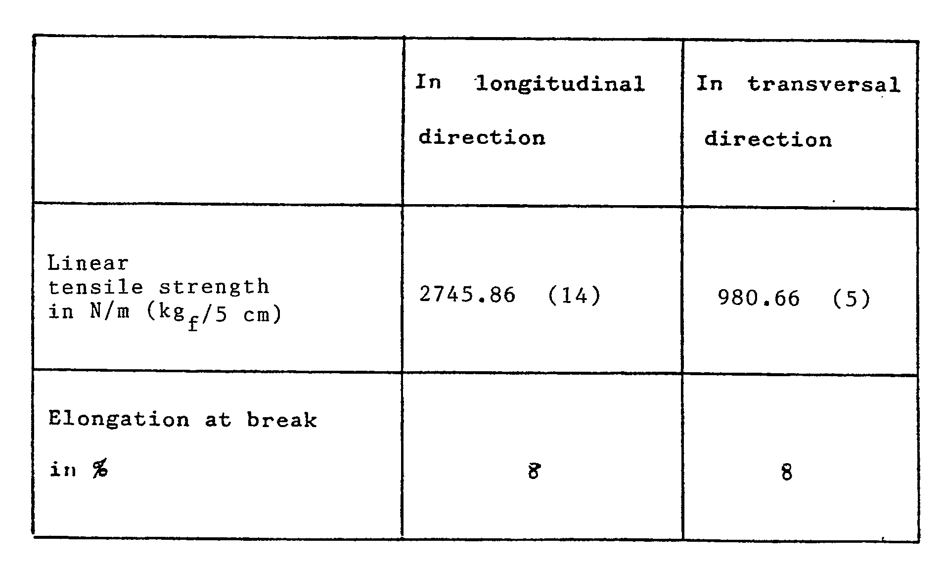
- The longitudinal fibrillated film exhibited a longitudinal linear tensile strength of 1372.93 N/m (7 kgf/5 cm) and an elongation at break of 8%, while the transversal fibrillated film exhibited a longitudinal linear tensile strength of 980.66 N/m (5 kgf/5 cm) and an elongation at break of 8%.
- The obtained reticular structure exhibited :
- Example 1 was repeated and to the manufactured article consisting of a first longitudinally arranged net of fibrillated films, of a second transversally arranged net of fibrillated films and of a third longitudinally arranged net there were added a fourth transversally arranged net of fibrillated films and a fifth longitudinally arranged net of fibrillated films.
- The fourth net and the fifth net had the same composition and properties as the corresponding underlying nets.
- The obtained reticular structure exhibited :

Claims (5)
- Reticular structures consisting of fibrillated films and having a high mechanical strength both in the longitudinal and in the transverse directions, characterized in that they consist of a first layer of one or more longitudinally arranged fibrillated films; of a second layer of one or more fibrillated films, which is superposed to the first layer and is arranged in such a manner that the extrusion and stretch direction of the films is perpendicular to the one of the film or films of the first layer, and of a third layer of one or more fibrillated films which is superposed to the second layer and is arranged in such a manner that the extrusion and stretch direction of the films is parallel with the one of the films of the first layer.
- Reticular structures according to claim 1, in which the fibrillated films of the various layers have the same composition and properties.
- Reticular structures according to claim 1, in which the fibrillated films of each layer have different composition and properties.
- Reticular structures according to claim 1, in which the longitudinally arranged fibrillated films have composition and properties which are different from those of the films of the perpendicularly arranged layer.
- Reticular structures according to any of the preceding claims, comprising a number of layers which are perpendicularly arranged and alternated with longitudinal layers.
Priority Applications (1)
| Application Number | Priority Date | Filing Date | Title |
|---|---|---|---|
| AT86106167T ATE68748T1 (en) | 1985-05-07 | 1986-05-06 | NETWORK STRUCTURES WITH MECHANICAL PROPERTIES. |
Applications Claiming Priority (2)
| Application Number | Priority Date | Filing Date | Title |
|---|---|---|---|
| IT2059585 | 1985-05-07 | ||
| IT20595/85A IT1185560B (en) | 1985-05-07 | 1985-05-07 | RETICULAR STRUCTURES HAVING IMPROVED MECHANICAL CHARACTERISTICS AND PROCEDURE AND DEVICE TO OBTAIN THEM |
Publications (3)
| Publication Number | Publication Date |
|---|---|
| EP0201076A2 EP0201076A2 (en) | 1986-11-12 |
| EP0201076A3 EP0201076A3 (en) | 1988-06-22 |
| EP0201076B1 true EP0201076B1 (en) | 1991-10-23 |
Family
ID=11169313
Family Applications (1)
| Application Number | Title | Priority Date | Filing Date |
|---|---|---|---|
| EP86106167A Expired - Lifetime EP0201076B1 (en) | 1985-05-07 | 1986-05-06 | Reticular structures having improved mechanical characteristics. |
Country Status (11)
| Country | Link |
|---|---|
| US (2) | US4861639A (en) |
| EP (1) | EP0201076B1 (en) |
| JP (1) | JPS6233857A (en) |
| AT (1) | ATE68748T1 (en) |
| AU (1) | AU584699B2 (en) |
| CA (1) | CA1291933C (en) |
| DE (1) | DE3682107D1 (en) |
| DK (1) | DK202386A (en) |
| IT (1) | IT1185560B (en) |
| NO (1) | NO861789L (en) |
| ZA (1) | ZA863363B (en) |
Families Citing this family (4)
| Publication number | Priority date | Publication date | Assignee | Title |
|---|---|---|---|---|
| JPH07358B2 (en) * | 1988-11-09 | 1995-01-11 | 日本石油化学株式会社 | Weather-resistant reticulated split membrane, its nonwoven fabric, and its manufacturing method |
| US5173138A (en) * | 1990-08-08 | 1992-12-22 | Blauch Denise A | Method and apparatus for the continuous production of cross-plied material |
| JP2988991B2 (en) * | 1990-10-04 | 1999-12-13 | 日本石油化学株式会社 | Nonwoven fabric, method for producing slit-shaped band used for the same, and slit forming roll used for the method |
| US5795426A (en) * | 1996-08-05 | 1998-08-18 | Boeing North American, Inc. | Method and apparatus for effecting continuous multi-directional laminating |
Citations (1)
| Publication number | Priority date | Publication date | Assignee | Title |
|---|---|---|---|---|
| GB1287336A (en) * | 1969-03-20 | 1972-08-31 | Polymer Processing Res Inst | Method of and apparatus for making a laminated body from pliable sheet material |
Family Cites Families (12)
| Publication number | Priority date | Publication date | Assignee | Title |
|---|---|---|---|---|
| GB1287366A (en) * | 1970-01-22 | 1972-08-31 | Ludwig Streng | Device for measuring the thickness of metallic layers |
| DE2149363A1 (en) * | 1971-10-02 | 1973-04-05 | Bosch Gmbh Robert | TWO-CIRCUIT BRAKE SYSTEM |
| DE2438265A1 (en) * | 1973-12-26 | 1975-07-10 | Sun Ventures Inc | ORIENTED, FIBRILLATED UNDER FOAM |
| JPS5142783A (en) * | 1974-10-09 | 1976-04-12 | Sanyo Kokusaku Pulp Co | Supuritsutoyaaniri kosasekisoshiitoseizohoho |
| GB1582945A (en) * | 1976-07-01 | 1981-01-21 | Univ Surrey | Manufacture of articles made from a water hardenable mass and a reinforcing element |
| NL7714571A (en) * | 1977-12-30 | 1979-07-03 | Stamicarbon | METHOD FOR MANUFACTURING ARTICLES FROM WATER-CURING MATERIAL |
| JPS54125272A (en) * | 1978-03-23 | 1979-09-28 | Kobunshi Kako Kenkyusho | Method of making reticulate crossed nonwoven with good strength |
| AU528009B2 (en) * | 1978-11-21 | 1983-03-31 | Stamicarbon B.V. | Sheet of fibre-reinforced hydraulically bindable material |
| EP0028867A3 (en) * | 1979-11-12 | 1981-08-26 | University Of Surrey | Composites of water-hardening substance and organic film networks and method of producing these composites |
| NL7909298A (en) * | 1979-12-22 | 1981-07-16 | Stamicarbon | METHOD FOR MANUFACTURING OBJECTS FROM WATER-HARDENED MATERIAL |
| US4503113A (en) * | 1982-03-12 | 1985-03-05 | Huyck Corporation | Papermaker felt with a three-layered base fabric |
| US4508113A (en) * | 1984-03-09 | 1985-04-02 | Chicopee | Microfine fiber laminate |
-
1985
- 1985-05-07 IT IT20595/85A patent/IT1185560B/en active
-
1986
- 1986-05-02 DK DK202386A patent/DK202386A/en unknown
- 1986-05-05 US US06/859,494 patent/US4861639A/en not_active Expired - Lifetime
- 1986-05-05 AU AU57127/86A patent/AU584699B2/en not_active Ceased
- 1986-05-05 ZA ZA863363A patent/ZA863363B/en unknown
- 1986-05-05 NO NO861789A patent/NO861789L/en unknown
- 1986-05-06 DE DE8686106167T patent/DE3682107D1/en not_active Expired - Fee Related
- 1986-05-06 EP EP86106167A patent/EP0201076B1/en not_active Expired - Lifetime
- 1986-05-06 AT AT86106167T patent/ATE68748T1/en not_active IP Right Cessation
- 1986-05-06 JP JP61102225A patent/JPS6233857A/en active Pending
- 1986-05-06 CA CA000508518A patent/CA1291933C/en not_active Expired - Fee Related
-
1989
- 1989-07-31 US US07/386,723 patent/US4933039A/en not_active Expired - Lifetime
Patent Citations (1)
| Publication number | Priority date | Publication date | Assignee | Title |
|---|---|---|---|---|
| GB1287336A (en) * | 1969-03-20 | 1972-08-31 | Polymer Processing Res Inst | Method of and apparatus for making a laminated body from pliable sheet material |
Also Published As
| Publication number | Publication date |
|---|---|
| EP0201076A2 (en) | 1986-11-12 |
| CA1291933C (en) | 1991-11-12 |
| EP0201076A3 (en) | 1988-06-22 |
| AU5712786A (en) | 1986-11-13 |
| NO861789L (en) | 1986-11-10 |
| IT8520595A0 (en) | 1985-05-07 |
| AU584699B2 (en) | 1989-06-01 |
| ZA863363B (en) | 1986-12-30 |
| DE3682107D1 (en) | 1991-11-28 |
| DK202386A (en) | 1986-11-08 |
| IT1185560B (en) | 1987-11-12 |
| ATE68748T1 (en) | 1991-11-15 |
| US4933039A (en) | 1990-06-12 |
| JPS6233857A (en) | 1987-02-13 |
| DK202386D0 (en) | 1986-05-02 |
| US4861639A (en) | 1989-08-29 |
Similar Documents
| Publication | Publication Date | Title |
|---|---|---|
| US7740042B2 (en) | Apparatus for vibration welding of sheet materials | |
| EP0099210B1 (en) | Mesh structure and laminate made therewith | |
| US3734812A (en) | Laminate product of crossed stretched tapes having perforations for air permeation and method for preparing the same | |
| US3864198A (en) | Interconnected network structures | |
| US4587148A (en) | Flocked floor mat with foraminous layer | |
| US5693400A (en) | Fusion-bonded carpet | |
| EP0368516B1 (en) | Fibrillated weatherproof webs having network structure, nonwoven fabrics made from the webs, and processes for the production of the webs and nonwoven fabrics | |
| JPH01207463A (en) | Mat consisting of filament loop aggregate and production thereof | |
| GB2214940A (en) | Mat consisting of filament loop aggregations | |
| CA1122383A (en) | Process for the manufacture of articles of water-hardening material | |
| SK127597A3 (en) | Method and device for making a composite material | |
| US4861639A (en) | Reticular structures having improved mechanical characteristics | |
| DE69323585T2 (en) | METHOD FOR PRODUCING A CARPET TILE | |
| US3142604A (en) | Apparatus for making non-woven pile fabrics | |
| US4487647A (en) | Process and device for the continuous production of glass fiber reinforced sheets of thermoplastic polymers | |
| US3041224A (en) | Method of forming foam layers on carpeting | |
| US5168000A (en) | Flat textile body | |
| CA1162372A (en) | Process and device for the preparation of composite reticular structures | |
| DE2438265A1 (en) | ORIENTED, FIBRILLATED UNDER FOAM | |
| US3547761A (en) | Extruded sheet material | |
| US4857127A (en) | Process for preparing improved oriented polymer films and tapes | |
| DE2013465B2 (en) | Device for the production of laminated bodies | |
| DE69421417T2 (en) | MELT-RELATED CARPET SYSTEM AND METHOD FOR PRODUCING IT | |
| CA1145516A (en) | Process for the manufacture of network packages | |
| DE2111884C (en) | Release paper |
Legal Events
| Date | Code | Title | Description |
|---|---|---|---|
| PUAI | Public reference made under article 153(3) epc to a published international application that has entered the european phase |
Free format text: ORIGINAL CODE: 0009012 |
|
| AK | Designated contracting states |
Kind code of ref document: A2 Designated state(s): AT BE CH DE FR GB LI NL SE |
|
| PUAL | Search report despatched |
Free format text: ORIGINAL CODE: 0009013 |
|
| AK | Designated contracting states |
Kind code of ref document: A3 Designated state(s): AT BE CH DE FR GB LI NL SE |
|
| 17P | Request for examination filed |
Effective date: 19880905 |
|
| 17Q | First examination report despatched |
Effective date: 19890913 |
|
| RAP1 | Party data changed (applicant data changed or rights of an application transferred) |
Owner name: RETIFLEX S.P.A. |
|
| GRAA | (expected) grant |
Free format text: ORIGINAL CODE: 0009210 |
|
| AK | Designated contracting states |
Kind code of ref document: B1 Designated state(s): AT BE CH DE FR GB LI NL SE |
|
| REF | Corresponds to: |
Ref document number: 68748 Country of ref document: AT Date of ref document: 19911115 Kind code of ref document: T |
|
| REF | Corresponds to: |
Ref document number: 3682107 Country of ref document: DE Date of ref document: 19911128 |
|
| ET | Fr: translation filed | ||
| PLBE | No opposition filed within time limit |
Free format text: ORIGINAL CODE: 0009261 |
|
| STAA | Information on the status of an ep patent application or granted ep patent |
Free format text: STATUS: NO OPPOSITION FILED WITHIN TIME LIMIT |
|
| 26N | No opposition filed | ||
| PGFP | Annual fee paid to national office [announced via postgrant information from national office to epo] |
Ref country code: GB Payment date: 19930423 Year of fee payment: 8 |
|
| PGFP | Annual fee paid to national office [announced via postgrant information from national office to epo] |
Ref country code: AT Payment date: 19930512 Year of fee payment: 8 |
|
| PGFP | Annual fee paid to national office [announced via postgrant information from national office to epo] |
Ref country code: SE Payment date: 19930517 Year of fee payment: 8 Ref country code: CH Payment date: 19930517 Year of fee payment: 8 |
|
| PGFP | Annual fee paid to national office [announced via postgrant information from national office to epo] |
Ref country code: NL Payment date: 19930531 Year of fee payment: 8 |
|
| PGFP | Annual fee paid to national office [announced via postgrant information from national office to epo] |
Ref country code: BE Payment date: 19930616 Year of fee payment: 8 |
|
| PG25 | Lapsed in a contracting state [announced via postgrant information from national office to epo] |
Ref country code: GB Effective date: 19940506 Ref country code: AT Effective date: 19940506 |
|
| PG25 | Lapsed in a contracting state [announced via postgrant information from national office to epo] |
Ref country code: SE Effective date: 19940507 |
|
| PG25 | Lapsed in a contracting state [announced via postgrant information from national office to epo] |
Ref country code: LI Effective date: 19940531 Ref country code: CH Effective date: 19940531 Ref country code: BE Effective date: 19940531 |
|
| BERE | Be: lapsed |
Owner name: RETIFLEX S.P.A. Effective date: 19940531 |
|
| PG25 | Lapsed in a contracting state [announced via postgrant information from national office to epo] |
Ref country code: NL Effective date: 19941201 |
|
| GBPC | Gb: european patent ceased through non-payment of renewal fee |
Effective date: 19940506 |
|
| NLV4 | Nl: lapsed or anulled due to non-payment of the annual fee | ||
| EUG | Se: european patent has lapsed |
Ref document number: 86106167.9 Effective date: 19941210 |
|
| REG | Reference to a national code |
Ref country code: CH Ref legal event code: PL |
|
| EUG | Se: european patent has lapsed |
Ref document number: 86106167.9 |
|
| PGFP | Annual fee paid to national office [announced via postgrant information from national office to epo] |
Ref country code: FR Payment date: 20030508 Year of fee payment: 18 |
|
| PGFP | Annual fee paid to national office [announced via postgrant information from national office to epo] |
Ref country code: DE Payment date: 20030526 Year of fee payment: 18 |
|
| PG25 | Lapsed in a contracting state [announced via postgrant information from national office to epo] |
Ref country code: DE Free format text: LAPSE BECAUSE OF NON-PAYMENT OF DUE FEES Effective date: 20041201 |
|
| PG25 | Lapsed in a contracting state [announced via postgrant information from national office to epo] |
Ref country code: FR Free format text: LAPSE BECAUSE OF NON-PAYMENT OF DUE FEES Effective date: 20050131 |
|
| REG | Reference to a national code |
Ref country code: FR Ref legal event code: ST |