EP0200930A1 - Air intake system for a reciprocating piston-type internal-combustion engine - Google Patents
Air intake system for a reciprocating piston-type internal-combustion engine Download PDFInfo
- Publication number
- EP0200930A1 EP0200930A1 EP86104644A EP86104644A EP0200930A1 EP 0200930 A1 EP0200930 A1 EP 0200930A1 EP 86104644 A EP86104644 A EP 86104644A EP 86104644 A EP86104644 A EP 86104644A EP 0200930 A1 EP0200930 A1 EP 0200930A1
- Authority
- EP
- European Patent Office
- Prior art keywords
- air
- intake system
- cylinders
- combustion engine
- air intake
- Prior art date
- Legal status (The legal status is an assumption and is not a legal conclusion. Google has not performed a legal analysis and makes no representation as to the accuracy of the status listed.)
- Withdrawn
Links
Images


Classifications
-
- F—MECHANICAL ENGINEERING; LIGHTING; HEATING; WEAPONS; BLASTING
- F02—COMBUSTION ENGINES; HOT-GAS OR COMBUSTION-PRODUCT ENGINE PLANTS
- F02B—INTERNAL-COMBUSTION PISTON ENGINES; COMBUSTION ENGINES IN GENERAL
- F02B27/00—Use of kinetic or wave energy of charge in induction systems, or of combustion residues in exhaust systems, for improving quantity of charge or for increasing removal of combustion residues
- F02B27/02—Use of kinetic or wave energy of charge in induction systems, or of combustion residues in exhaust systems, for improving quantity of charge or for increasing removal of combustion residues the systems having variable, i.e. adjustable, cross-sectional areas, chambers of variable volume, or like variable means
- F02B27/0226—Use of kinetic or wave energy of charge in induction systems, or of combustion residues in exhaust systems, for improving quantity of charge or for increasing removal of combustion residues the systems having variable, i.e. adjustable, cross-sectional areas, chambers of variable volume, or like variable means characterised by the means generating the charging effect
- F02B27/0247—Plenum chambers; Resonance chambers or resonance pipes
- F02B27/0252—Multiple plenum chambers or plenum chambers having inner separation walls, e.g. comprising valves for the same group of cylinders
-
- F—MECHANICAL ENGINEERING; LIGHTING; HEATING; WEAPONS; BLASTING
- F02—COMBUSTION ENGINES; HOT-GAS OR COMBUSTION-PRODUCT ENGINE PLANTS
- F02B—INTERNAL-COMBUSTION PISTON ENGINES; COMBUSTION ENGINES IN GENERAL
- F02B27/00—Use of kinetic or wave energy of charge in induction systems, or of combustion residues in exhaust systems, for improving quantity of charge or for increasing removal of combustion residues
- F02B27/02—Use of kinetic or wave energy of charge in induction systems, or of combustion residues in exhaust systems, for improving quantity of charge or for increasing removal of combustion residues the systems having variable, i.e. adjustable, cross-sectional areas, chambers of variable volume, or like variable means
- F02B27/0205—Use of kinetic or wave energy of charge in induction systems, or of combustion residues in exhaust systems, for improving quantity of charge or for increasing removal of combustion residues the systems having variable, i.e. adjustable, cross-sectional areas, chambers of variable volume, or like variable means characterised by the charging effect
- F02B27/0215—Oscillating pipe charging, i.e. variable intake pipe length charging
- F02B27/0221—Resonance charging combined with oscillating pipe charging
-
- F—MECHANICAL ENGINEERING; LIGHTING; HEATING; WEAPONS; BLASTING
- F02—COMBUSTION ENGINES; HOT-GAS OR COMBUSTION-PRODUCT ENGINE PLANTS
- F02B—INTERNAL-COMBUSTION PISTON ENGINES; COMBUSTION ENGINES IN GENERAL
- F02B27/00—Use of kinetic or wave energy of charge in induction systems, or of combustion residues in exhaust systems, for improving quantity of charge or for increasing removal of combustion residues
- F02B27/02—Use of kinetic or wave energy of charge in induction systems, or of combustion residues in exhaust systems, for improving quantity of charge or for increasing removal of combustion residues the systems having variable, i.e. adjustable, cross-sectional areas, chambers of variable volume, or like variable means
- F02B27/0226—Use of kinetic or wave energy of charge in induction systems, or of combustion residues in exhaust systems, for improving quantity of charge or for increasing removal of combustion residues the systems having variable, i.e. adjustable, cross-sectional areas, chambers of variable volume, or like variable means characterised by the means generating the charging effect
- F02B27/0247—Plenum chambers; Resonance chambers or resonance pipes
- F02B27/0263—Plenum chambers; Resonance chambers or resonance pipes the plenum chamber and at least one of the intake ducts having a common wall, and the intake ducts wrap partially around the plenum chamber, i.e. snail-type
-
- F—MECHANICAL ENGINEERING; LIGHTING; HEATING; WEAPONS; BLASTING
- F02—COMBUSTION ENGINES; HOT-GAS OR COMBUSTION-PRODUCT ENGINE PLANTS
- F02B—INTERNAL-COMBUSTION PISTON ENGINES; COMBUSTION ENGINES IN GENERAL
- F02B75/00—Other engines
- F02B75/16—Engines characterised by number of cylinders, e.g. single-cylinder engines
- F02B75/18—Multi-cylinder engines
- F02B2075/1804—Number of cylinders
- F02B2075/1832—Number of cylinders eight
-
- F—MECHANICAL ENGINEERING; LIGHTING; HEATING; WEAPONS; BLASTING
- F02—COMBUSTION ENGINES; HOT-GAS OR COMBUSTION-PRODUCT ENGINE PLANTS
- F02B—INTERNAL-COMBUSTION PISTON ENGINES; COMBUSTION ENGINES IN GENERAL
- F02B27/00—Use of kinetic or wave energy of charge in induction systems, or of combustion residues in exhaust systems, for improving quantity of charge or for increasing removal of combustion residues
- F02B27/02—Use of kinetic or wave energy of charge in induction systems, or of combustion residues in exhaust systems, for improving quantity of charge or for increasing removal of combustion residues the systems having variable, i.e. adjustable, cross-sectional areas, chambers of variable volume, or like variable means
- F02B27/0226—Use of kinetic or wave energy of charge in induction systems, or of combustion residues in exhaust systems, for improving quantity of charge or for increasing removal of combustion residues the systems having variable, i.e. adjustable, cross-sectional areas, chambers of variable volume, or like variable means characterised by the means generating the charging effect
- F02B27/0268—Valves
- F02B27/0273—Flap valves
-
- F—MECHANICAL ENGINEERING; LIGHTING; HEATING; WEAPONS; BLASTING
- F02—COMBUSTION ENGINES; HOT-GAS OR COMBUSTION-PRODUCT ENGINE PLANTS
- F02B—INTERNAL-COMBUSTION PISTON ENGINES; COMBUSTION ENGINES IN GENERAL
- F02B75/00—Other engines
- F02B75/16—Engines characterised by number of cylinders, e.g. single-cylinder engines
- F02B75/18—Multi-cylinder engines
- F02B75/22—Multi-cylinder engines with cylinders in V, fan, or star arrangement
-
- Y—GENERAL TAGGING OF NEW TECHNOLOGICAL DEVELOPMENTS; GENERAL TAGGING OF CROSS-SECTIONAL TECHNOLOGIES SPANNING OVER SEVERAL SECTIONS OF THE IPC; TECHNICAL SUBJECTS COVERED BY FORMER USPC CROSS-REFERENCE ART COLLECTIONS [XRACs] AND DIGESTS
- Y02—TECHNOLOGIES OR APPLICATIONS FOR MITIGATION OR ADAPTATION AGAINST CLIMATE CHANGE
- Y02T—CLIMATE CHANGE MITIGATION TECHNOLOGIES RELATED TO TRANSPORTATION
- Y02T10/00—Road transport of goods or passengers
- Y02T10/10—Internal combustion engine [ICE] based vehicles
- Y02T10/12—Improving ICE efficiencies
Definitions
- the invention relates to an air intake system according to the preamble of claim 1.
- the object of the invention is to further develop an air intake system so that it produces a torque increase without requiring a larger installation space.
- an opening which can be controlled by a rotary flap is provided in the partition and is released at speeds above approximately 4000 rpm.
- the individual suction pipes now suck in from the total volume of the air collection container and the torque remains up to a speed of approx. 5000 1 / min. at a constant height.
- the individual intake pipes are weakly bent, welded or cast together and form the top surface of the air collection container. Since they are thus integrated into the structure of the air collection container, this system requires a minimal installation space and can be produced at low manufacturing costs.
- the air intake system according to the invention is shown in the drawing and is explained in more detail below.
- a common air collection container 3 is on ordered, which is divided by a partition 4 into two equally large air spaces 5 and 6. From the air space 5, two individual suction pipes 5a and 5d lead to the cylinders 1a and 1d, two individual suction pipes 5b and 5c to the cylinders 2b and 2c of the other row of cylinders 2.
- the air space 6 is through individual suction pipes 6a and 6d with the cylinders 2a and 2d Individual suction pipes 6b and 6c connected to the cylinders 1b and 1c.
- the individual suction pipes all have an elongated length of about 300 mm.
- a rotary flap 8 is arranged, which is drawn in full in the open position and in dashed lines in the closed position. Even in the closed position, it has an air gap with the partition 4 in order to enable a slight exchange between the air spaces 5 and 6.
- intake pipes 9 and 10 with built-in throttle valves 11 and 12 lead via a pipe branch 13 to an air flow meter 14 and an air filter 15.
- a common throttle valve can also be used between the air flow meter 14 and the pipe branch 13 be used.
- the suction pipes 9 and 10 are designed to be quite long. Their length up to the pipe branch 13 is about twice as large as the stretched length of the individual suction pipes.
- the torque curve M d of an internal combustion engine as a function of its speed n achieved with such an air intake system is shown in FIG. 2.
- the curve e is obtained when the rotary flap 8 is open over the entire speed range or there is no partition, so the cylinders suck in from both air spaces. If you close the rotary flap in the entire speed range, so that the cylinders only suck in from one air space, either from 5 or from 6, it turns out a torque curve according to curve f with a torque increase of up to 10%. If you fit the rotary flap into the opening of the partition wall so that an air gap remains free, you get curve g, which shows a slightly lower torque increase. If you turn the flap at a speed n S about 3800 1 / min. goes into the open position, you avoid the sharp drop in torque after curve f. The torque remains constant in the speed range from 4000 to 5000 1 / min and is slightly above the torque, as can be seen in curve e.
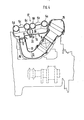
- an air intake system according to the invention is shown in cross section and longitudinal section, which is mounted between the two rows of cylinders of a V8 internal combustion engine.
- the air flow from the air filter 15 via the air flow meter 14 to the intake manifolds 9, 10 and to the air collection container 3 is curved and adapted to the contour of the housing 16 of the internal combustion engine.
- the air collection container 3 extends in the longitudinal direction of the internal combustion engine. Its top surface 17 is formed by the individual suction pipes 5d, 5c, 6c, 6d, 5d, 5a cast together. On its underside 18, the air flows into the two air spaces 5, 6.
- the axis 19 of the rotary flap 8 protrudes from the underside 18 of the air collecting container 3 and is provided with an actuating lever 20 with which the rotary flap starts at a speed n s of approximately 3800 1 / min. is opened automatically and is kept open in the entire upper speed range in order to obtain the desired torque curve g.
Abstract
Description
Die Erfindung betrifft eine Luftansauganlage nach dem Oberbegriff des Anspruchs 1.The invention relates to an air intake system according to the preamble of claim 1.
Bei einer aus DE-OS 34 08 499 bekannten Luftansauganlage sind die beiden Zylinderreihen einer Brennkraftmaschine an ein zwischen ihnen liegendes I-förmiges Verteilerstück aus zwei Resonanzbehältern und einem Verbindungsrohr angeschlossen. Wenn das Verteilerstück hinsichtlich Volumen sowie Querschnitt und Länge des Verbindungsrohres auf Resonanz abgestimmt ist, läßt sich durch Schwingaufladung ein hoher Füllungsgrad der Zylinder und somit eine Erhöhung des Drehmoments und der Leistung der Brennkraftmaschine erreichen. Nachteilig ist aber, daß diese Luftansauganlage bedingt durch das verhältnismäßig lange Verbindungsrohr einen großen Bauraum erfordert. Wenn sie oberhalb der Brennkraftmaschine angeordnet ist, deckt sie diese fast vollständig ab und muß bei Montagearbeiten an der Brennkraftmaschine abgebaut werden.In an air intake system known from DE-OS 34 08 499, the two rows of cylinders of an internal combustion engine are connected to an I-shaped distributor piece between them, comprising two resonance containers and a connecting pipe. If the distributor piece is tuned to resonance in terms of volume, cross section and length of the connecting tube, a high degree of filling of the cylinders and thus an increase in the torque and the power of the internal combustion engine can be achieved by means of vibrating charging. The disadvantage is that this air intake system requires a large amount of space due to the relatively long connecting pipe. If it is arranged above the internal combustion engine, it covers it almost completely and must be dismantled during assembly work on the internal combustion engine.
Die Aufgabe der Erfindung besteht darin, eine Luftansauganlage so weiter zu entwickeln, daß sie eine Drehmomenterhöhung erbringt, ohne einen größeren Bauraum erforderlich zu machen.The object of the invention is to further develop an air intake system so that it produces a torque increase without requiring a larger installation space.
Eine Lösung dieser Aufgabe gelingt mit den kennzeichnenden Merkmalen des Anspruchs 1. Bei dieser Konzeption ist nur ein Luftsammelbehälter vorgesehen, der durch eine Trennwand in zwei Lufträume unterteilt ist, an die die Einzelsaugrohre zu den Zylindern angeschlossen sind. Da ein Verbindungsrohr entbehrlich ist, baut die Luftansauganlage wesentlich kleiner. Durch eine geeignete Abstimmung des Volumens der Lufträume und der Länge der Einzelsaugrohre läßt sich eine beträchtliche Drehmomenterhöhung erreichen, insbesondere im unteren Drehzahlbereich der Brennkraftmaschine. Zur besseren Entkopplung der beiden Lufträume ist es vorteilhaft, wenn jeder Luftraum durch ein mit einer Drosselklappe steuerbares, verhältnismäßig langes Saugrohr an den gemeinsamen Luftfilter angeschlossen ist.A solution to this problem is achieved with the characterizing features of claim 1. In this conception, only one air collection container is provided, which is divided into two air spaces by a partition wall, to which the individual intake pipes are connected to the cylinders. Since a connecting pipe is not necessary, the air intake system is much smaller. A suitable adjustment of the volume of the air spaces and the length of the individual suction pipes allows a considerable one Achieve torque increase, especially in the lower speed range of the internal combustion engine. For better decoupling of the two air spaces, it is advantageous if each air space is connected to the common air filter by means of a relatively long suction pipe which can be controlled by a throttle valve.
Um ein Absinken des Drehmoments bei höheren Drehzahlen infolge Resonanzverstimmung zu vermeiden, ist in der Trennwand eine durch eine Drehklappe steuerbare öffnung vorhanden, die bei Drehzahlen oberhalb von ca. 4000 1/min freigegeben wird. Die Einzelsaugrohre saugen nun aus dem Gesamtvolumen des Luftsammelbehälters an und das Drehmoment bleibt bis zu einer Drehzahl von ca. 5000 1/min. auf konstanter Höhe.In order to prevent the torque from dropping at higher speeds as a result of resonance detuning, an opening which can be controlled by a rotary flap is provided in the partition and is released at speeds above approximately 4000 rpm. The individual suction pipes now suck in from the total volume of the air collection container and the torque remains up to a speed of approx. 5000 1 / min. at a constant height.
In bevorzugter konstruktiver Ausführung sind die Einzelsaugrohre schwach gebogen, miteinander verschweißt oder vergossen und bilden die Deckfläche des Luftsammelbehälters. Da sie somit in die Struktur des Luftsammelbehälters integriert sind, benötigt diese Anlage einen minimalen Einbauraum und ist mit geringen Fertigungskosten herstellbar.In a preferred design, the individual intake pipes are weakly bent, welded or cast together and form the top surface of the air collection container. Since they are thus integrated into the structure of the air collection container, this system requires a minimal installation space and can be produced at low manufacturing costs.
Die erfindungsgemäße Luftansauganlage ist in der Zeichnung dargestellt und wird nachfolgend näher erläutert.The air intake system according to the invention is shown in the drawing and is explained in more detail below.
Es zeigt
- Fig. 1 eine schematische Anordnung der Luftansauganlage,
- Fig. 2 Drehmoment-Drehzahl-Diagramm,
- Fig. 3 Querschnitt einer Luftansauganlage für eine V8-Brennkraftmaschine,
- Fig. 4 Schnitt nach Linie IV-IV der Fig. 3.
- 1 is a schematic arrangement of the air intake system,
- 2 torque-speed diagram,
- 3 cross section of an air intake system for a V8 internal combustion engine,
- 4 section along line IV-IV of FIG. 3rd
Die Luftansauganlage nach Fig. 1 dient für eine 8-Zylinder-Brennkraftmaschine mit zwei Reihen 1 und 2 von je 4 Ventilen 1a, 1b, 1c, 1d bzw. 2a, 2b, 2c, 2d. Zwischen den Zylinderreihen 1 und 2 ist ein gemeinsamer Luftsammelbehälter 3 angeordnet, der durch eine Trennwand 4 in zwei gleich große Lufträume 5 und 6 unterteilt ist. Von dem Luftraum 5 führen zwei Einzelsaugrohre 5a und 5d zu den Zylindern 1a und 1d, zwei Einzelsaugrohre 5b und 5c zu den Zylindern 2b und 2c der anderen Zylinderreihe 2. Der Luftraum 6 ist durch Einzelsaugrohre 6a und 6d mit den Zylindern 2a und 2d, durch Einzelsaugrohre 6b und 6c mit den Zylindern 1b und 1c verbunden. Die Einzelsaugrohre haben alle eine gestreckte Länge von etwa 300 mm. In einer öffnung 7 der Trennwand 4 ist eine Drehklappe 8 angeordnet, die in öffungsstellung voll und gestrichelt in Schließstellung gezeichnet ist. Auch in Schließstellung weist sie zu der Trennwand 4 einen Luftspalt auf, um einen geringen Austausch zwischen den Lufträumen 5 und 6 zu ermöglichen. Von den Lufträumen 5 und 6 führen Saugrohre 9 und 10 mit eingebauten Drosselklappen 11 und 12 über eine Rohrverzweigung 13 zu einem Luftmengenmesser 14 und einem Luftfilter 15. Anstelle der beiden Drosselklappen 11 und 12 kann auch eine gemeinsame Drosselklappe zwischen dem Luftmengenmesser 14 und der Rohrverzweigung 13 eingesetzt werden. Um die beiden Lufträume 5 und 6 bei geschlossener Drehklappe 8 schwingungsmäßig voneinander zu entkoppeln, sind die Saugrohr 9 und 10 recht lang ausgeführt. Ihre Länge bis zu der Rohrverzweigung 13 ist etwa doppelt so groß wie die gestreckte Länge der Einzelsaugrohre.1 serves for an 8-cylinder internal combustion engine with two
Der mit einer solchen Luftansauganlage erzielte Drehmomentverlauf Md einer Brennkraftmaschine in Abhängigkeit ihrer Drehzahl n ist in Fig. 2 dargestellt. Die Kurve e ergibt sich, wenn die Drehklappe 8 über den ganzen Drehzahlbereich offen ist bzw. keine Trennwand vorhanden ist, die Zylinder also aus beiden Lufträumen ansaugen. Schließt man die Drehklappe im ganzen Drehzahlbereich, so daß die Zylinder nur aus einem Luftraum, entweder aus 5 oder aus 6 ansaugen, so stellt sich ein Drehmomentverlauf nach Kurve f mit einer Drehmomentüberhöhung bis zu 10 % ein. Paßt man die Drehklappe in die öffnung der Trennwand so ein, daß ein Luftspalt frei bleibt, so erhält man die Kurve g, die eine etwas geringere Drehmoment- überhöhung zeigt. Wenn man die Drehklappe bei einer Drehzahl nS etwa gleich 3800 1/min. in öffnungsstellung geht, vermeidet man den starken Drehmomentabfall nach Kurve f. Das Drehmoment bleibt im Drehzalbereich von 4000 bis 5000 1/min konstant und liegt etwas oberhalb des Drehmoments, wie es sich entsprechend Kurve e ergibt.The torque curve M d of an internal combustion engine as a function of its speed n achieved with such an air intake system is shown in FIG. 2. The curve e is obtained when the
In den Fig. 3 und 4 ist eine Luftansauganlage gemäß der Erfindung im Querschnitt und Längsschnitt gezeigt, die zwischen beiden Zylinderreihen einer V8-Brennkraftmaschine angebaut ist. Die Luftführung vom Luftfilter 15 über den Luftmengenmesser 14 zu den Saugrohren 9, 10 und zum Luftsammelbehälter 3 ist gebogen ausgeführt und der Kontur des Gehäuses 16 der Brennkraftmaschine angepaßt. Der Luftsammelbehälter 3 erstreckt sich in Längsrichtung der Brennkraftmaschine. Seine Deckfläche 17 ist durch die miteinander vergossenen Einzelsaugrohre 5d, 5c, 6c, 6d, 5d, 5a gebildet. An seiner Unterseite 18 strömt die Luft in die beiden Lufträume 5, 6 ein. Die Achse 19 der Drehklappe 8 ragt aus der Unterseite 18 des Luftsammelbehälters 3 heraus und ist mit einem Betätigungshebel 20 versehen, mit dem die Drehklappe ab einer Drehzahl n s etwa 3800 1/min. selbsttätig geöffnet wird und im ganzen oberen Drehzahlbereich offen gehalten wird, um die erwünschte Drehmomentkurve g zu erhalten.3 and 4, an air intake system according to the invention is shown in cross section and longitudinal section, which is mounted between the two rows of cylinders of a V8 internal combustion engine. The air flow from the
Claims (10)
Applications Claiming Priority (2)
| Application Number | Priority Date | Filing Date | Title |
|---|---|---|---|
| DE19853516674 DE3516674A1 (en) | 1985-05-09 | 1985-05-09 | AIR SUCTION SYSTEM OF A PISTON PISTON INTERNAL COMBUSTION ENGINE |
| DE3516674 | 1985-05-09 |
Publications (1)
| Publication Number | Publication Date |
|---|---|
| EP0200930A1 true EP0200930A1 (en) | 1986-11-12 |
Family
ID=6270238
Family Applications (1)
| Application Number | Title | Priority Date | Filing Date |
|---|---|---|---|
| EP86104644A Withdrawn EP0200930A1 (en) | 1985-05-09 | 1986-04-04 | Air intake system for a reciprocating piston-type internal-combustion engine |
Country Status (3)
| Country | Link |
|---|---|
| EP (1) | EP0200930A1 (en) |
| JP (1) | JPS61258922A (en) |
| DE (1) | DE3516674A1 (en) |
Cited By (13)
| Publication number | Priority date | Publication date | Assignee | Title |
|---|---|---|---|---|
| EP0280121A2 (en) * | 1987-02-24 | 1988-08-31 | Bayerische Motoren Werke Aktiengesellschaft, Patentabteilung AJ-3 | Air plenum chamber |
| EP0387089A1 (en) * | 1989-03-09 | 1990-09-12 | Honda Giken Kogyo Kabushiki Kaisha | Intake system of plural cylinder internal combustion engine |
| EP0421116A1 (en) * | 1989-09-30 | 1991-04-10 | Dr.Ing.h.c. F. Porsche Aktiengesellschaft | Air intake system for a combustion engine |
| GB2248652A (en) * | 1989-10-12 | 1992-04-15 | Fuji Heavy Ind Ltd | Twin bank i.c. engine intake arrangement |
| WO1993000505A2 (en) * | 1991-06-24 | 1993-01-07 | Lotus Cars Limited | Intake manifold for a multi-cylinder internal combustion engine |
| EP0400952B1 (en) * | 1989-05-29 | 1995-07-12 | Honda Giken Kogyo Kabushiki Kaisha | Intake device for multi-cylinder internal combustion engine |
| EP0790393A1 (en) * | 1996-02-14 | 1997-08-20 | Bayerische Motoren Werke Aktiengesellschaft, Patentabteilung AJ-3 | Internal combustion engine having an intake system with a collector connected to opposite cylinder banks, especially for a V-8 engine |
| EP0987412A2 (en) * | 1998-09-18 | 2000-03-22 | Dr.Ing. h.c.F. Porsche Aktiengesellschaft | Intake system |
| EP1338772A2 (en) * | 2002-02-22 | 2003-08-27 | Filterwerk Mann + Hummel Gmbh | Internal combustion engine |
| WO2007009624A1 (en) * | 2005-07-22 | 2007-01-25 | Daimler Ag | Device having a unit for actuating an internal combustion engine |
| CN100387822C (en) * | 2004-10-06 | 2008-05-14 | 日产自动车株式会社 | Intake device of multi-cylinder engine |
| EP1961935A2 (en) * | 2007-02-23 | 2008-08-27 | Dr. Ing. h.c. F. Porsche Aktiengesellschaft | Switchable resonance suction unit for a combustion engine |
| CN111042961A (en) * | 2019-12-31 | 2020-04-21 | 潍柴动力股份有限公司 | Air inlet assembly and V-shaped engine |
Families Citing this family (5)
| Publication number | Priority date | Publication date | Assignee | Title |
|---|---|---|---|---|
| DE4014291C2 (en) * | 1990-05-04 | 1994-03-10 | Daimler Benz Ag | Suction system for a multi-cylinder, mixture-compressing internal combustion engine |
| DE4042415A1 (en) * | 1990-09-28 | 1992-11-19 | Daimler Benz Ag | IC engine with cylinder banks in V-formation - has two-part intake conduit, located above exhaust collection pipes, both within V-space |
| DE4432349A1 (en) * | 1994-09-12 | 1996-03-14 | Bayerische Motoren Werke Ag | Clapping valve assembly for air inlet of IC engines |
| DE10321323B3 (en) * | 2003-05-13 | 2004-12-16 | Dr.Ing.H.C. F. Porsche Ag | Intake system for an internal combustion engine with at least two rows of cylinder banks |
| JP4301074B2 (en) | 2004-05-12 | 2009-07-22 | トヨタ自動車株式会社 | Multi-cylinder engine intake system |
Citations (6)
| Publication number | Priority date | Publication date | Assignee | Title |
|---|---|---|---|---|
| US3303832A (en) * | 1967-02-14 | High output engines | ||
| GB2117043A (en) * | 1982-03-10 | 1983-10-05 | Ford Motor Co | Regulation of I.C. engine intake manifold resonance characteristics |
| EP0155685A2 (en) * | 1984-03-22 | 1985-09-25 | Mazda Motor Corporation | Intake system for V-type engine |
| EP0158008A2 (en) * | 1984-03-10 | 1985-10-16 | Dr.Ing.h.c. F. Porsche Aktiengesellschaft | Air inlet pipe arrangement for a multicylinder internal combustion engine |
| EP0159803A2 (en) * | 1984-04-16 | 1985-10-30 | General Motors Corporation | Engine intake system with modulated tuning |
| EP0177794A1 (en) * | 1984-10-10 | 1986-04-16 | Audi Ag | Inlet system for multi-cylinder engines |
-
1985
- 1985-05-09 DE DE19853516674 patent/DE3516674A1/en not_active Withdrawn
-
1986
- 1986-04-04 EP EP86104644A patent/EP0200930A1/en not_active Withdrawn
- 1986-05-08 JP JP61103986A patent/JPS61258922A/en active Pending
Patent Citations (6)
| Publication number | Priority date | Publication date | Assignee | Title |
|---|---|---|---|---|
| US3303832A (en) * | 1967-02-14 | High output engines | ||
| GB2117043A (en) * | 1982-03-10 | 1983-10-05 | Ford Motor Co | Regulation of I.C. engine intake manifold resonance characteristics |
| EP0158008A2 (en) * | 1984-03-10 | 1985-10-16 | Dr.Ing.h.c. F. Porsche Aktiengesellschaft | Air inlet pipe arrangement for a multicylinder internal combustion engine |
| EP0155685A2 (en) * | 1984-03-22 | 1985-09-25 | Mazda Motor Corporation | Intake system for V-type engine |
| EP0159803A2 (en) * | 1984-04-16 | 1985-10-30 | General Motors Corporation | Engine intake system with modulated tuning |
| EP0177794A1 (en) * | 1984-10-10 | 1986-04-16 | Audi Ag | Inlet system for multi-cylinder engines |
Cited By (19)
| Publication number | Priority date | Publication date | Assignee | Title |
|---|---|---|---|---|
| EP0280121A2 (en) * | 1987-02-24 | 1988-08-31 | Bayerische Motoren Werke Aktiengesellschaft, Patentabteilung AJ-3 | Air plenum chamber |
| EP0280121A3 (en) * | 1987-02-24 | 1989-09-27 | Bayerische Motoren Werke Aktiengesellschaft | Air plenum chamber |
| EP0387089A1 (en) * | 1989-03-09 | 1990-09-12 | Honda Giken Kogyo Kabushiki Kaisha | Intake system of plural cylinder internal combustion engine |
| EP0400952B1 (en) * | 1989-05-29 | 1995-07-12 | Honda Giken Kogyo Kabushiki Kaisha | Intake device for multi-cylinder internal combustion engine |
| US5063884A (en) * | 1989-09-30 | 1991-11-12 | Dr. Ing. H.C.F. Porsche Ag | Air intake system of an internal-combustion engine |
| EP0421116A1 (en) * | 1989-09-30 | 1991-04-10 | Dr.Ing.h.c. F. Porsche Aktiengesellschaft | Air intake system for a combustion engine |
| GB2248652A (en) * | 1989-10-12 | 1992-04-15 | Fuji Heavy Ind Ltd | Twin bank i.c. engine intake arrangement |
| WO1993000505A2 (en) * | 1991-06-24 | 1993-01-07 | Lotus Cars Limited | Intake manifold for a multi-cylinder internal combustion engine |
| WO1993000505A3 (en) * | 1991-06-24 | 1993-03-18 | Lotus Car | Intake manifold for a multi-cylinder internal combustion engine |
| EP0790393A1 (en) * | 1996-02-14 | 1997-08-20 | Bayerische Motoren Werke Aktiengesellschaft, Patentabteilung AJ-3 | Internal combustion engine having an intake system with a collector connected to opposite cylinder banks, especially for a V-8 engine |
| EP0987412A3 (en) * | 1998-09-18 | 2000-11-08 | Dr.Ing. h.c.F. Porsche Aktiengesellschaft | Intake system |
| EP0987412A2 (en) * | 1998-09-18 | 2000-03-22 | Dr.Ing. h.c.F. Porsche Aktiengesellschaft | Intake system |
| US6250272B1 (en) | 1998-09-18 | 2001-06-26 | Dr. Ing. H.C.F. Porsche Ag | Internal combustion engine suction system utilizing resonance |
| EP1338772A2 (en) * | 2002-02-22 | 2003-08-27 | Filterwerk Mann + Hummel Gmbh | Internal combustion engine |
| EP1338772A3 (en) * | 2002-02-22 | 2005-05-25 | Mann + Hummel GmbH | Internal combustion engine |
| CN100387822C (en) * | 2004-10-06 | 2008-05-14 | 日产自动车株式会社 | Intake device of multi-cylinder engine |
| WO2007009624A1 (en) * | 2005-07-22 | 2007-01-25 | Daimler Ag | Device having a unit for actuating an internal combustion engine |
| EP1961935A2 (en) * | 2007-02-23 | 2008-08-27 | Dr. Ing. h.c. F. Porsche Aktiengesellschaft | Switchable resonance suction unit for a combustion engine |
| CN111042961A (en) * | 2019-12-31 | 2020-04-21 | 潍柴动力股份有限公司 | Air inlet assembly and V-shaped engine |
Also Published As
| Publication number | Publication date |
|---|---|
| JPS61258922A (en) | 1986-11-17 |
| DE3516674A1 (en) | 1986-11-13 |
Similar Documents
| Publication | Publication Date | Title |
|---|---|---|
| EP0200930A1 (en) | Air intake system for a reciprocating piston-type internal-combustion engine | |
| EP0177794B1 (en) | Inlet system for multi-cylinder engines | |
| DE2702160C2 (en) | Suction system | |
| DE3502699C2 (en) | ||
| DE3711096C2 (en) | Intake system for a multi-cylinder internal combustion engine | |
| EP0389834A1 (en) | Arrangement of intake conduits for a multi-cylinder combustion engine | |
| DE3414710A1 (en) | COMBUSTION ENGINE WITH V-SHAPED CYLINDER ARRANGEMENT | |
| EP0987412B1 (en) | Intake system | |
| DE3433011C2 (en) | ||
| DE1476218C3 (en) | Intake arrangement for internal combustion engines with supercharging effect | |
| DE4117466A1 (en) | INTAKE SYSTEM FOR A MULTI-CYLINDER INTERNAL COMBUSTION ENGINE | |
| DE19535626C2 (en) | Intake silencer in a vertical engine | |
| DE2625788B1 (en) | EXHAUST PIPE FOR TURBOCHARGED COMBUSTION MACHINES | |
| DE3631124C2 (en) | Intake system for an internal combustion engine | |
| DE3628230C2 (en) | Intake system for internal combustion engines | |
| DE4039992C2 (en) | ||
| DE3728179C2 (en) | ||
| DE4110597C2 (en) | Intake air intake system for a multi-cylinder internal combustion engine | |
| DE69817005T2 (en) | TWO STROKE ENGINE | |
| DE3633929C2 (en) | Air intake system for a boxer or V-engine | |
| DE2930697C2 (en) | ||
| DE19509002C2 (en) | Thermostat mounting structure | |
| EP1178189B1 (en) | Intake system | |
| DE3923924C2 (en) | Control device for the intake manifold system of a vehicle internal combustion engine | |
| DE4032727C2 (en) | Intake system for multi-cylinder reciprocating internal combustion engine |
Legal Events
| Date | Code | Title | Description |
|---|---|---|---|
| PUAI | Public reference made under article 153(3) epc to a published international application that has entered the european phase |
Free format text: ORIGINAL CODE: 0009012 |
|
| AK | Designated contracting states |
Kind code of ref document: A1 Designated state(s): DE FR GB IT SE |
|
| 17P | Request for examination filed |
Effective date: 19870319 |
|
| 17Q | First examination report despatched |
Effective date: 19870818 |
|
| STAA | Information on the status of an ep patent application or granted ep patent |
Free format text: STATUS: THE APPLICATION HAS BEEN WITHDRAWN |
|
| 18W | Application withdrawn |
Withdrawal date: 19871111 |
|
| RIN1 | Information on inventor provided before grant (corrected) |
Inventor name: SCHMID, WOLFGANG |