EP0200884A2 - Gegentakt-Hochfrequenz-Leistungs-Teilungsaddiergerät - Google Patents
Gegentakt-Hochfrequenz-Leistungs-Teilungsaddiergerät Download PDFInfo
- Publication number
- EP0200884A2 EP0200884A2 EP86103251A EP86103251A EP0200884A2 EP 0200884 A2 EP0200884 A2 EP 0200884A2 EP 86103251 A EP86103251 A EP 86103251A EP 86103251 A EP86103251 A EP 86103251A EP 0200884 A2 EP0200884 A2 EP 0200884A2
- Authority
- EP
- European Patent Office
- Prior art keywords
- port
- ports
- pair
- phase
- output
- Prior art date
- Legal status (The legal status is an assumption and is not a legal conclusion. Google has not performed a legal analysis and makes no representation as to the accuracy of the status listed.)
- Withdrawn
Links
Images


Classifications
-
- H—ELECTRICITY
- H03—ELECTRONIC CIRCUITRY
- H03H—IMPEDANCE NETWORKS, e.g. RESONANT CIRCUITS; RESONATORS
- H03H7/00—Multiple-port networks comprising only passive electrical elements as network components
- H03H7/48—Networks for connecting several sources or loads, working on the same frequency or frequency band, to a common load or source
Definitions
- the present invention relates to passive radio-frequency circuitry and, more particularly, to a novel radio-frequency (RF) four-way power splitter/combiner apparatus operating in a push-pull mode.
- RF radio-frequency
- vacuum tube amplifiers are utilized to provide the relatively high RF excitation energy needed.
- solid-state devices capable of generating RF power outputs of the required magnitude are available at lower RF frequencies, and are expected to be shortly available at RF frequencies in the lower VHF region; use of solid-state power amplifiers is highly desirable, to provide the desired excitation signal: with larger bandwidth; over a longer lifetime (higher reliability); require simpler cooling systems; and cost less.
- providing even a highfrequency RF power amplifier with significant, e.g. greater than several hundred watts, power output requires that the output of several individual power amplifier modules, each capable of providing only a portion of the required output power, be combined.
- the input power for the plurality of amplifier modules must itself be provided by splitting a common input signal. Accordingly, it is highly desirable to provide apparatus having a common terminal and four other terminals, a first pair of which is at a 180° phase difference from a second pair of other terminals, and with the four-way apparatus being utilizable for either a power-splitting function, i.e. wherein the common port receives input power and the four ports each provide approximately one- fourth of the input power as driving power to an associated input of a different power amplifier, or as a power combiner, i.e. wherein the output power received at each of the four other ports is combined into a signal at the common output port.
- a power-splitting function i.e. wherein the common port receives input power and the four ports each provide approximately one- fourth of the input power as driving power to an associated input of a different power amplifier, or as a power combiner, i.e. wherein the output power received at each of the four other ports is combined into a signal at
- a four-way power splitter/combiner apparatus comprises five coaxial (unbalanced) ports, configured as a common port and four other ports, with power introduced into the common port, over a relatively wide frequency band, being substantially equally divided between the four other ports, with each of first and second pairs of ports having 180° phase difference between the pairs and with a first one of each pair of the other ports having a 0° signal phase difference from the remaining one of that port pair.
- coaxial cables of only the normal system impedance e.g. 50 ohms, are utilized; three or five ferrite-loaded transformation sections are used to provide each push-pull four-way power splitter/combiner apparatus.
- an illustrative high-power RF amplifier 10 contains a plurality of amplifier modules 11 and a plurality of power splitting/combining means 12, for amplifying the power output of an RF source 14, and providing the amplified power signal to a load 16.
- four power modules 11-1 through 11-4 are utilized, along with a pair of power splitting/combining means 12-1 and 12-2.
- Each of amplifier modules 11-1 through 11-4 has an associated RF signal input 11-1a through 11-4a and an associated RF signal output 11-1b through 11-4b.
- Each of signal inputs 11-1a through 11-4a is connected to one of a like number of a plurality of splitting/combining means ports 12-1 a through 12-1d, respectively, of first means 12-1, herein operating as a power splitting means.
- each respective power amplifier module output 11-1 through 11-4b is individually connected to an associated one of the respective four ports 12-2a through 12-2d of the second power means 12-2, herein operating as a power combining means.
- the four ports 12-1 a through 12-1d of power splitting means 12-1 can be considered as outputs A-D (or OUT A through OUT D), while the four ports 12-2a through 12-2d of power combining means 12-2 can be considered as inputs A-D (or IN A through IN D).
- Each of means 12 has a common RF port, e.g. common part 12-1e of the power splitting means and common port 12-2e of the power combining means.
- a common RF port e.g. common part 12-1e of the power splitting means and common port 12-2e of the power combining means.
- each of ports 12-1 a through 12-1d or 12-2a through 12-2d will be hereinafter referred to as a 4- port, and ports 12-1e and 12-2e will be referred to as a common port.
- the 4-ports are paired, with each pair of 4-ports, e.g. the pair of 4-ports port A and B or the pair of 4-ports C and D, having identical phase, e.g. a phase of about 0°, or about 180°, respectively, with respect to a signal at the common port; each pair of 4-ports thus has a phase difference of about 180° with respect to the other pair of 4-ports.
- Each 4-port provides a splitting/combining ratio of about 0 dB. with respect to the other 4-port of that pair; each pair has about a 0 dB. ratio with respect to the other pair.
- one pair of 4-ports e.g.
- ports A and B forms a push-pull configuration with the other pair of 4-ports, e.g. ports C and D.
- This provides the additional beneficial features normally obtained from push-pull amplifier operation, such as suppression of even harmonics of the operating RF frequency, and the like.
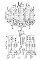
- Four-way apparatus 12' comprises first and second three-port hybrid circuits 18-1 and 18-2 each comprised of a pair of transmission line transformers 20-1 a and 20-1 b, or 20-2a and 20-2b, respectively, and an isolation resistance element 22-1 or 22-2, respectively.
- Coaxial balanced-to-unbalanced, or balun, transformer 24 is connected between the pair of transmission line transformers 18 and the apparatus common port 12'-1e.
- Each of the apparatus 4-ports 12'-1A through 12'-1D and the common port 12'-1 E are designed for optimum operation with the same load resistance R L , which is typically equal to the magnitude of the impedance of coaxial cables utilized within the system, e.g. 50 ohms and the like.
- R L load resistance
- a variable capacitance 26 is typically provided in shunt with each port, to allow any residual inductive impedance component to be compensated for.
- the 0° 4-ports 12'-1A and 12'-1B of the first transmission line transformer 18-1 are respectively provided with variable capacitive elements 26-1 and 26-2, settable to capacitive values C A and C B , respectively.
- the 180° 4-ports 12'1C and 12'1D of the second transmission line transformer 18-2 are respectively provided with variable capacitive elements 26-3 and 26-4, settable to capacitive values C c and C o , respectively.
- the output of each transmission line transformer 18-1 or 18-2, at the terminals labeled Z AB and Z co , respectively, has an effective unbalanced impedance substantially equal, in magnitude, to one-half the characteristic impedance, i.e. equal to (R L /2), with respect to circuit ground potential.
- Each of outputs Z AB and Z ⁇ has a phase of 180° with respect to the other.
- the impedances add and the total impedance between terminals 24a and 24b is a balanced impedance of R L ohms.
- This balanced impedance is converted, by transmission line balun 24, to an unbalanced impedance of magnitude R L , at common port 12'-1E. Any residual inductive impedance component at this common port is compensated for by variable capacitance 26-5, having an output capacitor value C o .
- Each of transmission line transformers 20-1a, 20-1b, 20-2a and 20-2b is constructed of a length of a coaxial cable 28, having an impedance Z o equal to the splitter/combiner apparatus load impedance R L value.
- Each coaxial transmission line 28 has a center conductor 29, having a first end 29a connected to the associated one of the four 4- ports, and having an opposite end 29b, connected to one end of the associated isolation resistor 22-1 or 22-2.
- a cylindrical sheath 30 of insulation dielectric material surrounds each center conductor 29, and is itself surrounded by a coaxial outer conductor 31.
- the coaxial outer conductor ends 31 a closest to the inner conductor ends connected to the associated 4-port, are connected together to form the respective transmission line transformer output terminals Z AB and Z cD .
- the opposite end 31 b of each coaxial cable is cross-connected to the center conductor end 29b of the opposite coaxial cable of that transmission line transformer 20 and, therefore, to an end of the associated isolation resistance 22.
- a plurality of magnetic decoupling elements 33 such as ferrite beads, cores, tubes and the like, generally having a toroidal shape, are placed about the outer conductor 31 of each transmission line assembly 20.
- Each of the transmission lines 28 is of a length, between opposite center conductor ends 29a and 29b, which is less than one-quarter of an effective wavelength at the maximum frequency of apparatus operation.
- Each of the ferrite decoupling elements 33 is chosen such that, when the desired number of such elements 30 are "strung" upon the associated coaxial element 28, the impedance measured between at least the outer conductor input and output ends 31 a and 31 b is relatively high in comparison to, e.g. at least an order of magnitude greater than, the characteristic impedance Z o of the coaxial cable 28 at the lowest frequency of desired operation.
- the balun transformer 24 is fabricated of a length of coaxial cable 34 having a characteristic impedance Z o equal to the apparatus port impedance R L - Coaxial cable 34 has a center conductor 35, having an input end 35a connected to the output of the first transmission line transformer means 18-1, and having an opposite end 35b connected to common connector 12-1E.
- a generally cylindrical member 36 of dielectric insulation material surrounds center conductor 35, and is itself surrounded by a cylindrical outer conductor 37. That outer conductive sheath end 37a closest to center conductor end 35a is connected to the output of the second transmission line transformer 18-2, while the opposite outer conductor end 37b is connected to system RF common potential at the common port end.
- the coaxial cable 34 of the balun transformer 24 is placed through the central apertures of another plurality of magnetic decoupling (ferrite) elements 39.
- Cable 34 can be run in a generally linear fashion through the plurality of ferrite elements 39, or may be wound about a single large ferrite element. Cables 38 can similarly be run through, or wound about, element 33.
- the ferrite elements 33 and/or 39 may exhibit a rise in temperature due to dissipation of RF power caused by unavoidable common mode currents and other unsymmetrical parameters.
- transmission balun line 24 As approximately twice the power in each of transmission line transformers 18 is present in transmission line balun 24, I generally prefer to make transmission balun line 24 of about twice the length of each of the transformer lines 20, and to use about twice as many ferrite elements 39 as elements 33, so that the losses per ferrite element are not increased in the transmission line balun.
- the actual form of coaxial cables 28 and 34, the particular materials and forms of elements 33 and 39, and the power ratings and configurations for isolation resistances 22, can all be selected from a wide range of readily-available, custom-available or custom-built components as necessary for the particular impedance and/or power levels and frequencies involved in a particular application of my novel 4-port push-pull power splitter/combiner apparatus.
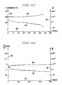
- a 4-port voltage V x Nyratio in decibels dB., is plotted along ordinate 51 and a 4-port pair-to-pair phase difference ⁇ - (which is "normalized” to zero by the addition of a 180° offset to the actual phase difference) is plotted along auxiliary ordinate 52, for frequencies plotted along abscissa 53.
- Curve 54 to be read with respect to ordinate 51, illustrates the change in the ratio of the voltage at 4-port A with respect to in-phase 4-port B (the ratio between the 0° pair of 4- ports).
- Curve 55 is the ratio of the voltage at one of the 180° 4- ports (4-port C) to one of the 0° 4-ports (4-port B). It will be seen that the in-phase 4-port signal amplitudes are within one-half of a decibel of each other over an extremely large frequency range, and that the push-pull voltage ratio (curve 55) is within about ⁇ 0.3 dB. over a frequency range from less than 2 MHz. to in excess of 200 MHz.
- phase between the 0° 4-ports A and B is, as shown by curve 57, within less than ⁇ 2 ° over the full frequency range, while the phase difference ⁇ (again normalized to zero by the addition of 180°) between 4-ports B and C is, as shown by curve 58, within about ⁇ 3 ° over a relatively wide frequency range (e.g. from about 20 MHz. to greater than 200 MHz.) and is within ⁇ 5° over an even larger frequency range.
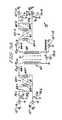
- splitter/combiner apparatus 12" utilizes a first coaxial transformer means 60-1 for combining the in-phase power provided at first and second input 4- ports 12"-1A and 12"-1B each providing, and operating with, a terminating impedance R L equal to the characteristic impedance of the coaxial members forming the various transformation means.
- a second transformer means 60-2 combines the in-phase power provided to another pair of 4-ports 12"-1C and 12"-1D.
- Each of transformer means 60-1 and 60-2 utilizes a magnetic member 61 through which, or about which, are wound transformer means windings 63-1 or 63-2, respectively.
- a resistive element 65-1 or 65-2, respectively, for absorbing unbalanced dissipative powers, is respectively connected between 4-ports 12"-1A and 12"-1 B, or 12"-1C and 12"-1D; each of balance resistances 65-1 and 65-2 are of resistance substantially equal to twice the port termination resistance R L .
- the transformation means 60-1 and 60-2 provide respective unbalanced output terminal 66-1 and 66-2 impedances Z' AB and Z' CD ; each output impedance is of a magnitude of one-half the common port termination value, i.e. a magnitude R L /2, with respect to circuit RF common potential, and is 180° out-of-phase with the other output terminal.
- a balanced impedance is provided between transformation means output terminals 66-1 and 66-2.
- the balanced impedance is of magnitude substantially equal to R L , and is present at the input of a balun transformer means 67.
- Transformer means 67 includes "windings" 69 about magnetic means 71.
- the unbalanced side of balun transformation means 67 is connected between common port 12"-1A and RF ground potential.
- a variable capacitance element 73-1 through 73-5 is provided in parallel with each of apparatus ports 12"-1 A through 12"-lE, to provide an associated capacitance of magnitude C A through C D and C o , respectively, to substantially compensate residual inductive reactance at the associated apparatus port.
- the pair of 2-to-1 impedance transformer means 60-1 and 60-2 with each transformer means having a single coaxial cable 63-1 or 63-2.
- the first end 74a of a center conductor is connected to 4-port 12"-1A and one end of resistance 65-1, while the other center conductor end 74b is connected to the transformation means output 66-1.
- the center conductor is surrounded by insulative dielectric material 75 and has an outer conductive sheath having a first end 76a, adjacent to first center conductor end 74a, which is connected to second center conductor end 74b and the output 66-1.
- the opposite outer conductor end 76b, adjacent to second center conductor end 74b, is connected to second 4-port 12"-1 B and the remaining end of resistance 65-1.
- the first end 74c of the center conductor is connected to output 66-2.
- the center conductor second end 74d is connected to second 4-port 12"-1 D and the one end of resistance 65-2.
- the center conductor is surrounded by insulative dielectric material 75 and has an outer conductive sheath having a first end 76c, adjacent to first center. conductor end 74c, which is connected to the remaining 4-port 12"-1c and the remaining end of resistance 65-2.
- the second outer conductor end 76d, adjacent to second center conductor end 74d, is connected to first center conductor end 74c and the second transformer output 66-2.
- Balun transformer means 67 utilizes a single coaxial cable 69, having a first center conductor end 77a connected to the output 66-1 of the first impedance transformer means 60-1 and having the center conductor second end 77b connected to common output connection means 12"-1E.
- the center conductor is supported by insulative dielectric material 78 within a tubular outer conductor having a first end 79a connected to the second transformation means output 66-2 and a second end 79b connected to RF common potential adjacent to common port connection means 12"-1 E.
- a plurality of ferrite decoupling elements 71 encloses the coaxial cable 69.
- a 4-port voltage Vx/Vyratio in decibels dB., is plotted along ordinate 90 and a 4-port pair-to-pair phase difference ⁇ (+180°) is plotted along auxiliary ordinate 91, for frequencies plotted along abscissa 92.
- Curve 94 to be read with respect to ordinate 90, illustrates the change in the ratio of the voltage at 4-port D with respect to the out-of-phase 4-port A (the ratio between a 180° pair of 4-ports). It will be seen that the push-pull voltage ratio, of curve 94, is within about ⁇ 0.3 dB. over a frequency range from less than 2 MHz. to at least 200 MHz.
- phase difference (normalized to zero by the addition of + 1 80 ° ) is represented by the quantity o between out-of-phase 4-ports B and C is, as shown by curve 95, within about ⁇ 3° over a relatively wide frequency range (e.g. from about 10 MHz. to at least 200 MHz.) and is within ⁇ 8° over an even larger frequency range.
- a wide-band 4-port splitter/combiner apparatus can be provided with a single balanced transformer and a pair of 2-port combining transformation means, to realize a relatively simple and physically compact 4-way power spfitting/combining apparatus having first and second pairs of ports, with the two ports in each pair being substantially in-phase with one another and with each port pair being substantially 180° out-of-phase with the opposite port pair, i.e. operating in a push-pull mode.
Landscapes
- Amplifiers (AREA)
- Transceivers (AREA)
- Cable Transmission Systems, Equalization Of Radio And Reduction Of Echo (AREA)
Applications Claiming Priority (2)
| Application Number | Priority Date | Filing Date | Title |
|---|---|---|---|
| US06/715,991 US4647868A (en) | 1985-03-25 | 1985-03-25 | Push-pull radio-frequency power splitter/combiner apparatus |
| US715991 | 1985-03-25 |
Publications (2)
| Publication Number | Publication Date |
|---|---|
| EP0200884A2 true EP0200884A2 (de) | 1986-11-12 |
| EP0200884A3 EP0200884A3 (de) | 1988-03-02 |
Family
ID=24876284
Family Applications (1)
| Application Number | Title | Priority Date | Filing Date |
|---|---|---|---|
| EP86103251A Withdrawn EP0200884A3 (de) | 1985-03-25 | 1986-03-11 | Gegentakt-Hochfrequenz-Leistungs-Teilungsaddiergerät |
Country Status (4)
| Country | Link |
|---|---|
| US (1) | US4647868A (de) |
| EP (1) | EP0200884A3 (de) |
| JP (1) | JPS61257010A (de) |
| IL (1) | IL78065A0 (de) |
Cited By (2)
| Publication number | Priority date | Publication date | Assignee | Title |
|---|---|---|---|---|
| WO2009090420A1 (en) * | 2008-01-16 | 2009-07-23 | Technetix Group Limited | Signal splitter |
| EP3346607A4 (de) * | 2015-09-01 | 2018-09-19 | Nec Corporation | Leistungsverstärkungsvorrichtung und fernsehsignalübertragungssystem |
Families Citing this family (41)
| Publication number | Priority date | Publication date | Assignee | Title |
|---|---|---|---|---|
| US4994760A (en) * | 1985-02-14 | 1991-02-19 | Signal One Corporation | Apparatus and method for combining output signals from parallelly coupled power field effect transistors in high frequency amplifiers |
| US4774481A (en) * | 1986-09-30 | 1988-09-27 | Rockwell International Corporation | Wideband transmission line signal combiner/divider |
| US5163181A (en) * | 1988-10-21 | 1992-11-10 | Harris Corporation | Multiple rf signal amplification method and apparatus |
| US4916410A (en) * | 1989-05-01 | 1990-04-10 | E-Systems, Inc. | Hybrid-balun for splitting/combining RF power |
| US5049836A (en) * | 1989-12-07 | 1991-09-17 | The United States Of America As Represented By The United States Department Of Energy | High voltage electrical amplifier having a short rise time |
| US5017886A (en) * | 1989-12-12 | 1991-05-21 | Comsat | RF power combiner using baluns |
| US5121090A (en) * | 1990-04-09 | 1992-06-09 | Tektronix, Inc. | Balun providing dual balanced outputs |
| US5066925A (en) * | 1990-12-10 | 1991-11-19 | Westinghouse Electric Corp. | Multi push-pull MMIC power amplifier |
| US5384603A (en) * | 1993-09-28 | 1995-01-24 | Multiplex Technology, Inc. | Video signal splitter with DC short circuit protection |
| TW280064B (de) * | 1994-09-29 | 1996-07-01 | Radio Frequency Systems Inc | |
| TW293968B (de) * | 1994-09-29 | 1996-12-21 | Radio Frequency Systems Inc | |
| US5701596A (en) * | 1994-12-01 | 1997-12-23 | Radio Frequency Systems, Inc. | Modular interconnect matrix for matrix connection of a plurality of antennas with a plurality of radio channel units |
| KR960027576A (ko) * | 1994-12-01 | 1996-07-22 | 리차드 탤런 | 육상 이동 무선 베이스 사이트에 사용되는 무선 신호 스캐닝 및 타겟팅 시스템 |
| US5617059A (en) * | 1995-07-07 | 1997-04-01 | Ssb Technologies, Inc. | Power amplifier, and associated method, for a microwave repeater station |
| US5628057A (en) * | 1996-03-05 | 1997-05-06 | Motorola, Inc. | Multi-port radio frequency signal transformation network |
| US6208833B1 (en) * | 1996-06-28 | 2001-03-27 | The Whitaker Corporation | Echo cancellation for a broadband distribution system |
| US6185182B1 (en) | 1996-07-26 | 2001-02-06 | Radio Frequency Systems, Inc. | Power sharing amplifier system for a cellular communications system |
| US6201439B1 (en) | 1997-09-17 | 2001-03-13 | Matsushita Electric Industrial Co., Ltd. | Power splitter/ combiner circuit, high power amplifier and balun circuit |
| US5982252A (en) * | 1998-04-27 | 1999-11-09 | Werlatone, Inc. | High power broadband non-directional combiner |
| US6381212B1 (en) | 1998-06-17 | 2002-04-30 | Radio Frequency Systems, Inc. | Power sharing amplifier system for amplifying multiple input signals with shared power amplifiers |
| US6246299B1 (en) | 1999-07-20 | 2001-06-12 | Werlatone, Inc. | High power broadband combiner having ferrite cores |
| US6545564B1 (en) | 2000-04-25 | 2003-04-08 | Signal Technology Corporation | RF signal divider |
| US6486749B1 (en) | 2000-05-05 | 2002-11-26 | Ophir Rf, Inc. | Four-way power combiner/splitter |
| US7027790B2 (en) * | 2001-08-10 | 2006-04-11 | Broadcom Corporation | Transceiver front-end |
| US7573839B2 (en) * | 2004-07-07 | 2009-08-11 | Broadcom Corporation | Line driver for an adaptive hybrid circuit |
| US7248130B2 (en) * | 2005-01-05 | 2007-07-24 | Bae Systems Information And Electronic Systems Integration Inc. | High power combiner/divider |
| US8026775B2 (en) * | 2007-02-20 | 2011-09-27 | Bae Systems Information And Electronic Systems Integration Inc. | Decade bandwidth planar MMIC four port transformer |
| US8362835B2 (en) | 2006-02-17 | 2013-01-29 | Gradual Tech Software L.L.C. | Decade bandwidth planar MMIC four port transformer |
| US7719381B2 (en) * | 2006-05-16 | 2010-05-18 | Harris Corporation | Transmission line balun for broadband combiners, splitters and transformers |
| US8031003B2 (en) | 2006-05-17 | 2011-10-04 | Dishop Steven M | Solid-state RF power amplifier for radio transmitters |
| US7538609B2 (en) * | 2007-01-26 | 2009-05-26 | Infineon Technologies Ag | Amplifier, transmitter arrangement having an amplifier and method for amplifying a signal |
| GB2458953B (en) * | 2008-04-04 | 2010-09-15 | Univ Dublin City | Power splitter |
| US8354894B2 (en) | 2009-04-30 | 2013-01-15 | Harris Corporation | RF signal combiner/splitter and related methods |
| US8648669B1 (en) * | 2012-08-15 | 2014-02-11 | Werlatone, Inc. | Planar transmission-line interconnection and transition structures |
| US8493162B1 (en) * | 2012-08-15 | 2013-07-23 | Werlatone, Inc. | Combiner/divider with coupled transmission line |
| US8482362B1 (en) | 2012-08-15 | 2013-07-09 | Werlatone, Inc. | Combiner/divider with interconnection structure |
| US9261587B1 (en) * | 2013-03-15 | 2016-02-16 | Raytheon Company | Methods and apparatus for highly reliable signal distribution |
| US9130536B2 (en) | 2013-07-23 | 2015-09-08 | Tokyo Electron Limited | Radio frequency signal splitter and matcher |
| US11082186B2 (en) | 2019-09-25 | 2021-08-03 | Raytheon Company | Phased array antenna system |
| US10978772B1 (en) | 2020-10-27 | 2021-04-13 | Werlatone, Inc. | Balun-based four-port transmission-line networks |
| CN113098412B (zh) * | 2021-03-30 | 2022-09-06 | 电子科技大学 | 一种大功率全固态射频电源合成电路 |
Family Cites Families (6)
| Publication number | Priority date | Publication date | Assignee | Title |
|---|---|---|---|---|
| NL113982C (de) * | 1960-05-21 | |||
| FR1293543A (fr) * | 1961-01-17 | 1962-05-18 | Portenseigne Ets Marcel | Perfectionnements aux répartiteurs d'énergie haute fréquence |
| FR1498927A (fr) * | 1966-11-08 | 1967-10-20 | Western Electric Co | Amplificateur à couplage différentiel |
| US3735289A (en) * | 1971-11-26 | 1973-05-22 | Collins Radio Comp | Transmitter combiner having coupled tuned circuits |
| US4121180A (en) * | 1976-12-27 | 1978-10-17 | Technical Research And Manufacturing, Inc. | Broadband directional coupler |
| DE2744862C2 (de) * | 1977-10-05 | 1982-07-08 | Endress U. Hauser Gmbh U. Co, 7867 Maulburg | Aus Koaxialleitungsstücken gebildeter Hochfrequenztransformator |
-
1985
- 1985-03-25 US US06/715,991 patent/US4647868A/en not_active Expired - Fee Related
-
1986
- 1986-03-06 IL IL78065A patent/IL78065A0/xx unknown
- 1986-03-11 EP EP86103251A patent/EP0200884A3/de not_active Withdrawn
- 1986-03-24 JP JP61064277A patent/JPS61257010A/ja active Pending
Cited By (6)
| Publication number | Priority date | Publication date | Assignee | Title |
|---|---|---|---|---|
| WO2009090420A1 (en) * | 2008-01-16 | 2009-07-23 | Technetix Group Limited | Signal splitter |
| US8058948B2 (en) | 2008-01-16 | 2011-11-15 | Technetix Group Limited | Signal splitter with improved transmisson line transformer |
| EP3346607A4 (de) * | 2015-09-01 | 2018-09-19 | Nec Corporation | Leistungsverstärkungsvorrichtung und fernsehsignalübertragungssystem |
| US10361661B2 (en) | 2015-09-01 | 2019-07-23 | Nec Corporation | Power amplification apparatus and television signal transmission system |
| US10498293B2 (en) | 2015-09-01 | 2019-12-03 | Nec Corporation | Power amplification apparatus and television signal transmission system |
| US10873298B2 (en) | 2015-09-01 | 2020-12-22 | Nec Corporation | Power amplification apparatus and television signal transmission system |
Also Published As
| Publication number | Publication date |
|---|---|
| JPS61257010A (ja) | 1986-11-14 |
| EP0200884A3 (de) | 1988-03-02 |
| IL78065A0 (en) | 1986-07-31 |
| US4647868A (en) | 1987-03-03 |
Similar Documents
| Publication | Publication Date | Title |
|---|---|---|
| US4647868A (en) | Push-pull radio-frequency power splitter/combiner apparatus | |
| US6407648B1 (en) | Four-way non-directional power combiner | |
| US5982252A (en) | High power broadband non-directional combiner | |
| US6246299B1 (en) | High power broadband combiner having ferrite cores | |
| US9065161B2 (en) | Baluns, a fine balance and impedance adjustment module, a multi-layer transmission line, and transmission line NMR probes using same | |
| US7683718B2 (en) | Solid-state RF power amplifier for radio transmitters | |
| KR101705606B1 (ko) | 유도자-커패시터-유도자 고출력 결합기 | |
| EP0409851B1 (de) | VERTEILTER SYMMETRISCHER VERSTäRKER | |
| EP0855794B1 (de) | Breitbandimpedanzanpassungstransformator | |
| JPH06224605A (ja) | Rf電力増幅器用の結合器 | |
| US20060061431A1 (en) | Broadband transmission line transformer | |
| EP1166440B1 (de) | Transformator mit ubermittlungsleitung für impedanzanpassung | |
| Grebennikov | Power combiners, impedance transformers and directional couplers | |
| US6121853A (en) | Broadband coupled-line power combiner/divider | |
| US5334957A (en) | RF high power, two and three way in phase combiner and method | |
| US3317849A (en) | Hybrid circuit for radio frequency signal processing apparatus | |
| CN113659300A (zh) | 宽带四功分器 | |
| US4859971A (en) | R-segment transmission line directional coupler | |
| KR102755329B1 (ko) | 트랜스포머 기반 증폭기, 이의 동작 방법, 및 이를 포함하는 장치들 | |
| US3886499A (en) | High frequency electrical network with frequency dependent characteristics having a constant input resistance | |
| US6572287B1 (en) | Assembly of an impedance transformer and a balun transformer | |
| Borg et al. | Radio‐frequency power combiner for cw and pulsed applications | |
| US3134082A (en) | Transmission device having a preferred transmission direction | |
| US4050072A (en) | Signal combining apparatus | |
| US3091739A (en) | Transistor multicoupler with plural outputs |
Legal Events
| Date | Code | Title | Description |
|---|---|---|---|
| PUAI | Public reference made under article 153(3) epc to a published international application that has entered the european phase |
Free format text: ORIGINAL CODE: 0009012 |
|
| AK | Designated contracting states |
Kind code of ref document: A2 Designated state(s): CH DE FR GB IT LI NL SE |
|
| PUAB | Information related to the publication of an a document modified or deleted |
Free format text: ORIGINAL CODE: 0009199EPPU |
|
| RA1 | Application published (corrected) |
Date of ref document: 19861217 Kind code of ref document: A2 |
|
| PUAL | Search report despatched |
Free format text: ORIGINAL CODE: 0009013 |
|
| AK | Designated contracting states |
Kind code of ref document: A3 Designated state(s): CH DE FR GB IT LI NL SE |
|
| STAA | Information on the status of an ep patent application or granted ep patent |
Free format text: STATUS: THE APPLICATION IS DEEMED TO BE WITHDRAWN |
|
| 18D | Application deemed to be withdrawn |
Effective date: 19880905 |
|
| RIN1 | Information on inventor provided before grant (corrected) |
Inventor name: MUELLER, OTWARD MARIA |