EP0200643A2 - Two-port synthetic aperture radar system - Google Patents
Two-port synthetic aperture radar system Download PDFInfo
- Publication number
- EP0200643A2 EP0200643A2 EP86400892A EP86400892A EP0200643A2 EP 0200643 A2 EP0200643 A2 EP 0200643A2 EP 86400892 A EP86400892 A EP 86400892A EP 86400892 A EP86400892 A EP 86400892A EP 0200643 A2 EP0200643 A2 EP 0200643A2
- Authority
- EP
- European Patent Office
- Prior art keywords
- port
- vector
- target
- mover
- ports
- Prior art date
- Legal status (The legal status is an assumption and is not a legal conclusion. Google has not performed a legal analysis and makes no representation as to the accuracy of the status listed.)
- Withdrawn
Links
Images


Classifications
-
- G—PHYSICS
- G01—MEASURING; TESTING
- G01S—RADIO DIRECTION-FINDING; RADIO NAVIGATION; DETERMINING DISTANCE OR VELOCITY BY USE OF RADIO WAVES; LOCATING OR PRESENCE-DETECTING BY USE OF THE REFLECTION OR RERADIATION OF RADIO WAVES; ANALOGOUS ARRANGEMENTS USING OTHER WAVES
- G01S13/00—Systems using the reflection or reradiation of radio waves, e.g. radar systems; Analogous systems using reflection or reradiation of waves whose nature or wavelength is irrelevant or unspecified
- G01S13/02—Systems using reflection of radio waves, e.g. primary radar systems; Analogous systems
- G01S13/50—Systems of measurement based on relative movement of target
- G01S13/52—Discriminating between fixed and moving objects or between objects moving at different speeds
-
- G—PHYSICS
- G01—MEASURING; TESTING
- G01S—RADIO DIRECTION-FINDING; RADIO NAVIGATION; DETERMINING DISTANCE OR VELOCITY BY USE OF RADIO WAVES; LOCATING OR PRESENCE-DETECTING BY USE OF THE REFLECTION OR RERADIATION OF RADIO WAVES; ANALOGOUS ARRANGEMENTS USING OTHER WAVES
- G01S13/00—Systems using the reflection or reradiation of radio waves, e.g. radar systems; Analogous systems using reflection or reradiation of waves whose nature or wavelength is irrelevant or unspecified
- G01S13/88—Radar or analogous systems specially adapted for specific applications
- G01S13/89—Radar or analogous systems specially adapted for specific applications for mapping or imaging
- G01S13/90—Radar or analogous systems specially adapted for specific applications for mapping or imaging using synthetic aperture techniques, e.g. synthetic aperture radar [SAR] techniques
- G01S13/9021—SAR image post-processing techniques
- G01S13/9029—SAR image post-processing techniques specially adapted for moving target detection within a single SAR image or within multiple SAR images taken at the same time
Definitions
- the present invention relates to a radar system and more particularly to a two-antenna (port) synthetic aperture system that attains detection of a target and determines its relative radial velocity and angular position from digital signal processing of the radar returns.
- Each port is motion compensated for each radar transmitted pulse.
- the motion of the radar platform is matched to the antenna spacings in a manner such that, at the occurrence of each radar- transmitted pulse, the antenna moves exactly one antenna spacing. Therefore, in a three-port system, the last two antenna ports receive radar return data at the previous antenna position for three successive transmitted pulses. Phase compensation may be employed if positions are not exactly equal to the antenna spacing.
- each antenna port occupies the same position in space; and three radar clutter returns from the ground will have the same amplitude and phase, but objects moving on the ground (movers) will have different positions and consequently will customarily have a different amplitude and phase.
- three ports may be considered as being spaced along a platform on a moving vehicle, such as an aircraft.
- Each of the ports radiates electromagnetic energy and, as the three ports move relative to a target, such as a ground based target, the second and third ports will see identical ground clutter.
- a target such as a ground based target
- the second and third ports will see identical ground clutter.
- there is a moving target on the ground there will be a displacement of the target when the second port arrives at the physical position that the first port occupied an instant before.
- This displacement also occurs for the detected signal by the third port when it moves to the position occupied by the second port an instant before.
- the displacement of such a mover results in phase shift of processed signals at the individual ports, which corresponds to relative radial velocity and the true target azimuth position, as will be now discussed in connection with the figures.
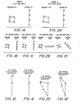
- FIG. 1A-FIG. 5 indicate the three-port vector diagram technique for determining relative radial velocity of a mover. These diagrams, for purposes of illustration, have been simplified in a number of aspects to show the theory of operation.
- the return signals are vectorally represented for the case of a first mover in the absence of clutter, before and after spectral processing (FFT).
- FFT spectral processing
- the signals from the first mover at the first port have the same spectral lines as clutter at that port.
- the ground returns appear identical.
- return signals from the first mover at the second port are phase shifted by 90° per pulse when compared with the return signals of clutter at port 2.
- the first mover in port 2 is phase shifted with respect to the first mover in port 1 as is apparent from the returns of FIGS. 1B and 23.
- FIGS. 1C, 2C and 3C illustrate corresponding vector diagrams for a second mover which has a ifferent radial velocity.
- FIGS. 1D, 2D and 3D the resultant of the first mover round return plus the clutter return is vectorally epresanted by respective vectors M and C.
- the umulative vector effect of the second mover and clutter is ndicated in FIGS. IE, 2E and 3E.
- phase shift in the second and third ort signals occurs for the first and second mover vectors elative to the clutter vector due to the motion of the lover.
- the second port will see a displaced target when that port occupies the position in space that the first port occupied an instant previously.
- the third port occupies the position in space which the 5 econd port occupied an instant previously, it will see the target displaced from the position it previously had, all of which results in the phase shift of the mover vector relative to the clutter vector.
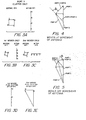
- FIG. 4 the vector diagram is illustrated for the determination of relative radial velocity of a first mover.
- the vector diagram in FIG. 4 indicates each of the resultant vectors from ports 1-3 previously explained in connection with FIGS. 1D, 2D and 3D. These are respectively indicated in FIG. 4 as the vectors for ports 1, 2. and 3.
- Each of these vectors is not drawn to the same scale as FIGS. 1D, 2D and 3D but rather are drawn to exaggerate the differences of the resultant vectors at the ports so that phase determination can be more clearly indicated.
- the angle ⁇ which is the phase difference between the vectors (port 1-port 2) and (port 2-port 3).
- the indicated phase difference of 90° is proportional to the relative radial velocity of the first mover target which generated the returns at the three ports.
- the true azimuth position of the target also depends upon this phase angle.
- the phase angle will be 90° as indicated in FIG. 4. Accordingly, the first mover target discussed herein lies along the boresight of the antenna which generated the first mover returns at ports 1, 2 and 3.
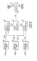
- the signals at ports 1, 2, and 3 undergo separate spectral processing employing the mentioned Fast Fourier Transform (FFT) at blocks 10, 12 and 14.
- FFT Fast Fourier Transform
- Vector subtraction of port I-port 2 occurs in vector subtractor 16 while the vector subtraction for port 2-port 3 occurs in vector subtractor 18.
- a phase processor 24 determines the phase angle from the subtracted vector inputs at 20, 22.
- the output from phase processor 24 undergoes computing at 26 to determine the relative radial velocity and azimuth position by computations well known in the art.
- FIGS. 1C, 2C and 3C illustrate the four-pulse-return vector diagram of the second mover only, in the absence of clutter, before and after spectral processing by means of Fast Fourier Transforms.
- the resultant vector diagrams of the second mover plus clutter, after processing, is respectively indicated for each port in FIGS. IE, 2E and 3E.
- FIG. 5 where the vectors from ports 1, 2 and 3, for the second mover, are illustrated with the second mover resultant vectors for (port 1-port 2) and (port 2-port 3).
- FIG. 6 accomplishes the latter-mentioned vector subtractions; and phase detector 24 determines the phase angle illustrated in FIG. 5 which again is determinative of target relative radial velocity and true azimuth position.
- the angle is no longer 90° which would be in line with ooresight, as was the case of the first mover as shown in FIG. 4.
- the phase angle indicates a true azimuth position which is off boresight and represents a relative radial target velocity different from that of the first mover (FIG. 4).
- the moving targets are detected in ports 1, 2 and 3. They are detected in a doppler bin proportional to their true azimuth position plus their relative radial velocity.
- the phase shift between port 1-port 2 and port 2-port 3 is equivalent to a doppler bin that is matched to the phase shift between these vectors. This is proportional to the relative radial velocity.
- the true target azimuth position is proportional to the phase difference due to its azimuth position. This is an equivalent doppler bin.
- the true azimuth position is proportional to the doppler bin of the detected target in port 1, 2, 3 minus the equivalent doppler bin of the relative radial velocity.
- the result of the three-port system is the detection of a moving target and measurement by prior art techniques of various target parameters such as relative radial velocity, true azimuth position and even amplitude and range.
- V DV Doppler due to target relative radial velocity of target to radar antenna
- V DA Doppler due to relative radial velocity due to a radar return existing at an angle relative to the boresight of an antenna
- Vp A the velocity of the aircraft (V) which carries the radar platform, further knowing the wavelength of the radar transmitted frequency, it is a straightforward matter to compute 6 which is the angular deviation of the target from the boresight of the antenna indicated at reference numeral 30 in FIG. 6.
- the present invention is directed to a two-port clutter suppression interferometry system which is capable of attaining approximately the same results as a three-port system.
- a two-port system implementation one less antenna is required along with a third less hardware associated with it; and there is a significant redaction in the complexity and cost as well as an increase in inherent reliability.
- each port of the radar data is spectrally processed, by conventional means such as Fast Fourier Transforms. However, the processing occurs in a sliding window or independent segment fashion. Vector subtraction of port outputs results in a phase angle which is proportional to radial velocity and from which true zimuth target position can be determined as in the prior rt three-port system.
- the inventive two-port clutter suppression interferometer is shown in block diagram form in FIG. 12.
- the improved system basically attains all of the information of the prior art three-port system but, as indicated in FIG. 12, only two antenna ports are employed.
- Each port of the radar data is an input to a corresponding Fast Fourier Transform or other known, appropriate spectral processor 10', 12'.
- it is time processed in a sliding window fashion which permits the system to obtain a time history of a moving target.
- segment processing such as sliding window processing, a vector is the amplitude and phase of a resulting velocity vector but does not determine the relative radial velocity of the mover in the presence of clutter.
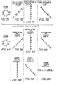
- FIGS. 7A-9D are vector diagrams for the two-port system of FIG. 12 and they illustrate the concept of the two-port system.
- the number of radar returns is eleven in numbe., but this is by way of example only. In actuality, the number of returns may be from a few to hundreds.
- a spectrally processed signal at a single frequency is shown wherein the phase shift between radar returns is 45°.
- a further simplifying assumption is an ideal noiseless processing system.
- the processing relies upon a sliding window process which, per se, is known in the art.
- Sliding window processing is shown in FIG. 11.
- the uppermost ulse train comprises a first sliding window pulse train (START 1) separated from a second by a predetermined elapsed time.
- the second pulse train is designated as START 2, and so on up to and including START 4.
- Each succeeding pulse train differs from a prior pulse train by a tine delay of a single pulse interval, but may differ by multiple pulse intervals.
- FIGS. 7A-7D if we examine port 1 or port 2, the clutter is identical in both ports. However, at the different STARTS 1-3, sliding window spectral processing causes the clutter output starting phase to change 45°, as shown in FIGS. 7B-7D.
- the starting phase of the clutter vector for a particular port changes 45° with the start time.
- Each clutter vector start time would be a phase shift change proportional to the filtering that the clutter undergoes. If it were a 10° phase shift filter, for each sliding window processing (START 1-3), the phase change between starts would be 10°. The amplitude of the clutter would remain the same. Therefore, the clutter vector starting phase would change with the filter and the starting time of the radar return (sliding window processing) and is predictable and computable).
- the mover vector in port I is shown during succeeding start conditions in FIGS. 8B-8D and they appear in the same filter as the clutter and add to the clutter vector. This is the same for port 2, as shown in FIGS. 9B-9D, except that the mover vector has changed starting phase from those of port 1 and therefore the resultant vector of clutter plus mover is not zero (as with clutter only). This is a vector without any indication of radial velocity.
- FIG. 10 illustrates the three clutter and mover vectors for ports 1 and 2, which results from three different sliding window processing conditions.
- the clutter vector is indicated by reference numeral 32 while the mover vector at port 1 is indicated by 34. This is also indicated as the START 1-port 1 condition (Sl-Pl).
- the mover vector 44 is rotated by a 45° phase shift between phase differences of the sliding window processing. This is indicated as the START 2-Port 2 condition (S2-P2).
- S2-P2 START 2-Port 2 condition
- the resultant mover vector occurring as a result of the subtraction of port 1 minus port 2 is resultant vector 46 which establishes a reference for ompletion of phase angle measurement as will be presently een.
- the loving target Since the processing occurs over a time period ypically approaching a quarter of a second or more, the loving target cannot stay in one range and/or doppler bin. ' he moving target will be moving from one range and/or Doppler bin to another. The consequence of motion of the moving target is that the mover changes in amplitude from one sliding window processing to the next, as typified by vectors 38 and 54. This target change in range and/or Doppler will result in a change in amplitude of the return Where first detected and a change in the resultant vector 52 after a subtraction of vectors at ports 1 and 2.
- the resultant vector 46 shown in FIG. 10 is indicative of a START 1 condition for port I-port 2 and this indicates the mover target. If at the next sliding window processing START 2, the moving target has changed slightly in velocity, then the mover will appear in the same spectral processing doppler filter. The amplitude of the output of the doppler filter will then change substantially.
- the resultant mover vector 52 changes an amplitude when compared to that of 46 but will be parallel to it after 46 extended (58) is rotated 45 degrees to position 56 where it forms a reference line for the phase change corresponding to subsequent start time 2. If the intersections 48, 50 are connected to respective vectors 38, 54, a triangle is produced that determines the phase change ⁇ between the two resultant mover vectors.
- the phase change measured by processor 24 (FIG. 12) is proportional to relative radial velocity of the target. Hence, we have determined the relative radial velocity by two sliding window processing conditions of radar returns where the clutter is correlated and predictable and the mover due to its motion has changed in doppler which results in a change in amplitude of the mover. Similar phase and relative radial velocity determinations are made at subsequent condition START 3.
- Reference line 56 is extended at 63 and rotated by the 45 degree shift dictated by the sliding window processing to reference line 61.
- Mover vectors 42 and 60 form resultant vector 66 which, when located parallel to reference line 61, establishes another triangle subtending the next phase change indicative of relative radial velocity at START 3.
- a moving target has to have one or more of the aforementioned attributes or it would not be a moving target.
- the true azimuth position may be determined at output 30, as in the prior z ! rt three-port system
Landscapes
- Engineering & Computer Science (AREA)
- Remote Sensing (AREA)
- Radar, Positioning & Navigation (AREA)
- Physics & Mathematics (AREA)
- Computer Networks & Wireless Communication (AREA)
- General Physics & Mathematics (AREA)
- Electromagnetism (AREA)
- Radar Systems Or Details Thereof (AREA)
Abstract
A two-port (port 1, 2) radar system measures the amplitude and phase clutter of target returns at both ports during staggered time intervals when sliding window processing occurs. Clutter returns remain constant but target returns from a moving target, between successive intervals, generate a phase difference indicative of relative radial target velocity.
Description
- The present invention relates to a radar system and more particularly to a two-antenna (port) synthetic aperture system that attains detection of a target and determines its relative radial velocity and angular position from digital signal processing of the radar returns.
- Three radar antennas or ports, employing three simultaneously synthetic aperture arrays, have been used for clutter suppression interferometry. Each port is motion compensated for each radar transmitted pulse. The motion of the radar platform is matched to the antenna spacings in a manner such that, at the occurrence of each radar- transmitted pulse, the antenna moves exactly one antenna spacing. Therefore, in a three-port system, the last two antenna ports receive radar return data at the previous antenna position for three successive transmitted pulses. Phase compensation may be employed if positions are not exactly equal to the antenna spacing. Assuming exact spacing for three successively transmitted pulses, each antenna port occupies the same position in space; and three radar clutter returns from the ground will have the same amplitude and phase, but objects moving on the ground (movers) will have different positions and consequently will customarily have a different amplitude and phase.
- In a prior art three-port system, data from each antenna port is spectrally processed utilizing a well-known Fast Fourier Transform (FFT). During a particular time interval there are "N" transmitted pulses and "M" range bins. In each range bin the "N" returns are spectrally processed in each antenna port. In each range bin of each port there are "N" doppler bin outputs. The doppler bin outputs correspond to the doppler signals detected at each antenna port. The outputs from
antenna ports port 2 is subtracted from that ofport 1. If there are no movers, but just clutter, the subtraction will theoretically equal zero signifying no mover present. By subtracting the output signal vectors from the three ports, a phase angle is obtained which is proportional to the relative radial velocity of a target (mover) and is determinative of target true azimuth position. - In a simplified system of the prior art, three ports (antennas) may be considered as being spaced along a platform on a moving vehicle, such as an aircraft. Each of the ports radiates electromagnetic energy and, as the three ports move relative to a target, such as a ground based target, the second and third ports will see identical ground clutter. However, if there is a moving target on the ground (mover), there will be a displacement of the target when the second port arrives at the physical position that the first port occupied an instant before. This displacement also occurs for the detected signal by the third port when it moves to the position occupied by the second port an instant before. The displacement of such a mover results in phase shift of processed signals at the individual ports, which corresponds to relative radial velocity and the true target azimuth position, as will be now discussed in connection with the figures.
- FIG. 1A-FIG. 5 indicate the three-port vector diagram technique for determining relative radial velocity of a mover. These diagrams, for purposes of illustration, have been simplified in a number of aspects to show the theory of operation.
- What is shown is only four transmitted pulses per antenna port, instead of the hundreds that would actually be processed in a practical system. The spectrally processed signals from the four returns are vectorally added in a filter that is matched to an equivalent frequency. Because the antenna motion is compensated for in each port, the clutter in a particular doppler bin is the same in all ports. Thus, by way of example, if the signal at the second port were subtracted from that at the first port, or if the signal at the third port were subtracted from the second port, with only clutter present, the subtraction process would yield a null. Therefore, as indicated in FIG. lA-FIG. 3A, the clutter ground returns for the illustrated four transmitted pulses per antenna, in all three ports, look exactly alike in all corresponding range doppler bins.
- Referring to FIG. 1B, the return signals are vectorally represented for the case of a first mover in the absence of clutter, before and after spectral processing (FFT). As indicated, the signals from the first mover at the first port have the same spectral lines as clutter at that port. To view this another way, since the first mover occupies the same range doppler bin as the clutter in
port 1, the ground returns appear identical. Considering FIGS. 2A and 23, return signals from the first mover at the second port are phase shifted by 90° per pulse when compared with the return signals of clutter atport 2. The first mover inport 2 is phase shifted with respect to the first mover inport 1 as is apparent from the returns of FIGS. 1B and 23. It is this phase difference as detected by adjacent ports of an antenna, in response to a moving target, which is employed to determine relative radial velocity of the first mover. Inasmuch as the clutter is considered, it has no phase shift between ports. Similarly, inport 3 the first mover has a phase shift relative to the first mover inport 2, in the same doppler bin, as is apparent from the vector diagrams of FIGS. 23 and 33. FIGS. 1C, 2C and 3C illustrate corresponding vector diagrams for a second mover which has a ifferent radial velocity. - In FIGS. 1D, 2D and 3D the resultant of the first mover round return plus the clutter return is vectorally epresanted by respective vectors M and C. Similarly, the umulative vector effect of the second mover and clutter is ndicated in FIGS. IE, 2E and 3E. As will be observed in FIGS. 2D, 2E, 3D and 3E, phase shift in the second and third ort signals occurs for the first and second mover vectors elative to the clutter vector due to the motion of the lover. In other words, as an antenna platform moves elative to a target, the second port will see a displaced target when that port occupies the position in space that the first port occupied an instant previously. Similarly, when the third port occupies the position in space which the 5econd port occupied an instant previously, it will see the target displaced from the position it previously had, all of which results in the phase shift of the mover vector relative to the clutter vector.
- In FIG. 4 the vector diagram is illustrated for the determination of relative radial velocity of a first mover. The vector diagram in FIG. 4 indicates each of the resultant vectors from ports 1-3 previously explained in connection with FIGS. 1D, 2D and 3D. These are respectively indicated in FIG. 4 as the vectors for
ports - The true azimuth position of the target also depends upon this phase angle. In the event that the boresight of the antenna is coincident with the true azimuth position, the phase angle will be 90° as indicated in FIG. 4. Accordingly, the first mover target discussed herein lies along the boresight of the antenna which generated the first mover returns at
ports - In an implementation of the three-port system as shown in FIG. 6, the signals at
ports blocks port 2 occurs invector subtractor 16 while the vector subtraction for port 2-port 3 occurs invector subtractor 18. Aphase processor 24 determines the phase angle from the subtracted vector inputs at 20, 22. The output fromphase processor 24 undergoes computing at 26 to determine the relative radial velocity and azimuth position by computations well known in the art. - In order to better illustrate the technique of the three-port system, a second mover or target will now be discussed, this mover not being at the boresight of the antenna as was the case with the first mover. FIGS. 1C, 2C and 3C illustrate the four-pulse-return vector diagram of the second mover only, in the absence of clutter, before and after spectral processing by means of Fast Fourier Transforms. The resultant vector diagrams of the second mover plus clutter, after processing, is respectively indicated for each port in FIGS. IE, 2E and 3E. These latter-mentioned resultant vectors are employed in the vector diagram of FIG. 5 where the vectors from
ports phase detector 24 determines the phase angle illustrated in FIG. 5 which again is determinative of target relative radial velocity and true azimuth position. In the situation shown in FIG. 5, the angle is no longer 90° which would be in line with ooresight, as was the case of the first mover as shown in FIG. 4. For the second mover shown in FIG. 5, the phase angle indicates a true azimuth position which is off boresight and represents a relative radial target velocity different from that of the first mover (FIG. 4). - The moving targets are detected in
ports port 2 and port 2-port 3 is equivalent to a doppler bin that is matched to the phase shift between these vectors. This is proportional to the relative radial velocity. - The true target azimuth position is proportional to the phase difference due to its azimuth position. This is an equivalent doppler bin. The true azimuth position is proportional to the doppler bin of the detected target in
port - In order to gain a better appreciation between the various doppler parameters and measured characteristics of a moving target, the overall relationship of vector quantities may be expressed as:

- VDA equals Doppler due to relative radial velocity due to a radar return existing at an angle relative to the boresight of an antenna;

- The vector subtraction previously discussed yields the value of Δφ and VDT is the total doppler detected by the
spectral processor 10 as indicated in FIG. 6. The original equation may then be transformed as follows:
- Inasmuch as the quantities on the right side of the equation are known, the quantity VDA may be solved. In order to further solve for azimuth position, it is necessary to consider the expression:

- Having solved for VpA and being able to obtain the velocity of the aircraft (V) which carries the radar platform, further knowing the wavelength of the radar transmitted frequency, it is a straightforward matter to compute 6 which is the angular deviation of the target from the boresight of the antenna indicated at
reference numeral 30 in FIG. 6. - The present invention is directed to a two-port clutter suppression interferometry system which is capable of attaining approximately the same results as a three-port system. However, as a consequence of the two-port system implementation, one less antenna is required along with a third less hardware associated with it; and there is a significant redaction in the complexity and cost as well as an increase in inherent reliability.
- - In the present invention only two antenna ports are employed; and basically, the same functions are performed on the two ports as were performed in the case of the prior art three-port system. Each port of the radar data is spectrally processed, by conventional means such as Fast Fourier Transforms. However, the processing occurs in a sliding window or independent segment fashion. Vector subtraction of port outputs results in a phase angle which is proportional to radial velocity and from which true zimuth target position can be determined as in the prior rt three-port system.
- The above-mentioned objects and advantages of the resent invention will be more clearly understood when considered in conjunction with the accompanying drawings, in which:
- FIGS. lA, 2A and 3A are vector representations of :lutter at three separate ports of the prior art system;
- FIGS. 1B and 1C are vector representations of a first and second target, respectively, at a first port of a prior art system;
- FIGS. 2B and 2C are vector representations of a first and second target, respectively, at a second port of a prior art system;
- FIGS. 3B and 3C are vector representations of a first and second target, respectively, at a third port of a prior art system;
- FIGS. 1D and 1E are vector representations of first and second targets, respectively, at a first port of the prior art system;
- FIGS. 2D and 2E are vector representations of first and second targets, respectively, at a second port of the prior art system;
- FIGS. 3D and 3E are vector representations of first and second targets, respectively, at a third port of the prior art system;
- FIG. 4 is a three-port vector diagram of a prior art system for a first target;
- FIG. 5 is a three-port vector diagram of a prior art system for a second target;
- FIG. 6 is a block diagram of a prior art three-port system;
- FIGS. 7A-7D are vector representations of clutter only, it first or second ports, of the present invention;
- FIG. 8A is a vector representation of a mover before spectral processing;
- FIGS. 8B-8D are vector representations of a mover at a first port of the invention at subsequent time intervals;
- FIGS. 9B-9D are vector representations of a mover at a second port of the invention at subsequent time intervals;
- FIG. 10 is a composite vector diagram at
ports - FIG. 11 is a diagrammatic representation of sliding window processing as employed for the present invention; and
- FIG. 12 is a block diagram of the present two-port system.
- Now that the prior art three-port system has been discussed in detail, the present invention will be disoussed in connection with a two-port system which accomplishes essentially the same functions as the three-port system with one-third less complexity and attendant hardware.
- The inventive two-port clutter suppression interferometer is shown in block diagram form in FIG. 12. The improved system basically attains all of the information of the prior art three-port system but, as indicated in FIG. 12, only two antenna ports are employed. Each port of the radar data is an input to a corresponding Fast Fourier Transform or other known, appropriate spectral processor 10', 12'. However, it is time processed in a sliding window fashion which permits the system to obtain a time history of a moving target. Without utilizing segment processing, such as sliding window processing, a vector is the amplitude and phase of a resulting velocity vector but does not determine the relative radial velocity of the mover in the presence of clutter.
- FIGS. 7A-9D are vector diagrams for the two-port system of FIG. 12 and they illustrate the concept of the two-port system. As indicated in these vector diagrams, the number of radar returns is eleven in numbe., but this is by way of example only. In actuality, the number of returns may be from a few to hundreds. Further, a spectrally processed signal at a single frequency is shown wherein the phase shift between radar returns is 45°. A further simplifying assumption is an ideal noiseless processing system.
- The processing relies upon a sliding window process which, per se, is known in the art. Sliding window processing is shown in FIG. 11. The uppermost ulse train comprises a first sliding window pulse train (START 1) separated from a second by a predetermined elapsed time. The second pulse train is designated as
START 2, and so on up to and includingSTART 4. Each succeeding pulse train differs from a prior pulse train by a tine delay of a single pulse interval, but may differ by multiple pulse intervals. - FIG. 7A indicates the clutter return signals for
port 1 orport 2 before spectral processing (FFT). As will be noted, each vector is displaced from a preceding vector by 45°. FIGS. 7B-7D respectively illustrate vector diagrams for the clutter returns after spectral processing wherein all of the clutter return vectors in each figure are oriented with the same phase angle and forrespective START anc 3 conditions. - FIG. 8A corresponds with that of FIG. 7A but represents the returns from a mover before spectral processing. FIGS. 8B-8D correspond to the vector diagrams of FIGS. 7B-7D, except that the returns are from a mover, after spectral processing and they respectively represent returns from port 1-
START - FIGS. 9B-9D correspond to the vector diagrams of a mover as illustrated in FIGS. 8B-8D but with
port 2 being represented forSTART - Considering FIGS. 7A-7D, if we examine
port 1 orport 2, the clutter is identical in both ports. However, at the different STARTS 1-3, sliding window spectral processing causes the clutter output starting phase to change 45°, as shown in FIGS. 7B-7D. The starting phase of the clutter vector for a particular port changes 45° with the start time. Each clutter vector start time would be a phase shift change proportional to the filtering that the clutter undergoes. If it were a 10° phase shift filter, for each sliding window processing (START 1-3), the phase change between starts would be 10°. The amplitude of the clutter would remain the same. Therefore, the clutter vector starting phase would change with the filter and the starting time of the radar return (sliding window processing) and is predictable and computable). - The mover vector in port I is shown during succeeding start conditions in FIGS. 8B-8D and they appear in the same filter as the clutter and add to the clutter vector. This is the same for
port 2, as shown in FIGS. 9B-9D, except that the mover vector has changed starting phase from those ofport 1 and therefore the resultant vector of clutter plus mover is not zero (as with clutter only). This is a vector without any indication of radial velocity. - FIG. 10 illustrates the three clutter and mover vectors for
ports - Referring in greater detail to FIG. 10, during
START 1 the clutter vector is indicated byreference numeral 32 while the mover vector atport 1 is indicated by 34. This is also indicated as the START 1-port 1 condition (Sl-Pl). Atport 2 themover vector 44 is rotated by a 45° phase shift between phase differences of the sliding window processing. This is indicated as the START 2-Port 2 condition (S2-P2). The resultant mover vector occurring as a result of the subtraction ofport 1 minusport 2 isresultant vector 46 which establishes a reference for ompletion of phase angle measurement as will be presently een. - Since the processing occurs over a time period ypically approaching a quarter of a second or more, the loving target cannot stay in one range and/or doppler bin. 'he moving target will be moving from one range and/or Doppler bin to another. The consequence of motion of the moving target is that the mover changes in amplitude from one sliding window processing to the next, as typified by
vectors resultant vector 52 after a subtraction of vectors atports - Observation of the mover vectors shows that the mover vector amplitude is the same in
port 1 andport 2. If the mover changes slightly in velocity, then the phase shift between mover vectors is approximately equal; and the amplitude will change appreciably. Theresultant vector 46 shown in FIG. 10 is indicative of aSTART 1 condition for port I-port 2 and this indicates the mover target. If at the next slidingwindow processing START 2, the moving target has changed slightly in velocity, then the mover will appear in the same spectral processing doppler filter. The amplitude of the output of the doppler filter will then change substantially. Theresultant mover vector 52 changes an amplitude when compared to that of 46 but will be parallel to it after 46 extended (58) is rotated 45 degrees to position 56 where it forms a reference line for the phase change corresponding tosubsequent start time 2. If theintersections respective vectors subsequent condition START 3. -
Reference line 56 is extended at 63 and rotated by the 45 degree shift dictated by the sliding window processing toreference line 61.Mover vectors resultant vector 66 which, when located parallel toreference line 61, establishes another triangle subtending the next phase change indicative of relative radial velocity atSTART 3. There are various actions of the moving target which cause it to change in amplitude. They are the following: - a) significant movement from one doppler bin toward the next due to tangential velocity of target,
- b) significant movement from one range bin toward the next due to radial velocity of the target,
- c) radial acceleration of target causing it to move significantly from one doppler bin toward the next, or
- d) scintillation of target,
- e) target surface vibration,
- f) combinations of the above.
- Therefore, a moving target has to have one or more of the aforementioned attributes or it would not be a moving target.
- It is noted that the aforementioned discussion is simplified to exclude phase changes of moving targets which would modify FIG. 10 by imposing a corresponding angular shift of a triangle relative to its clutter vector. Such a target phase change would occur if the target moved along boresight at changing velocity or if the target accelerated.
- Referring to FIG. 12, when the radial velocity is determined at
output 28 ofcomputer 26, the true azimuth position may be determined atoutput 30, as in the prior z!rt three-port system, - It should be understood that the invention is not limited to the exact details of construction shown and described herein for obvious modifications will occur to persons skilled in the art.
Claims (5)
1. A method for determining relative radial velocity of a target in the presence of clutter, the method comprising the steps:
spectrally processing doppler radar returns (10', 12') from two antenna ports (port 1, 2) during first timing intervals;
spectrally processing doppler radar returns (10', 12') from the two antenna ports during second timing intervals, delayed with respect to the first intervals;
subtracting (16) return vectors as processed from each of the two ports at succeeding intervals;
forming a resultant reference first vector from the vectors, subtracted from the two ports during first and second succeeding intervals;
forming a resultant second vector from the vectors subtracted from the two ports during second and third succeeding intervals;
orienting the resultant second vector in predetermined angular relationship to the reference vector; and
calculating (24, 26) the phase angle subtended by the resultant second vector which is proportional to the relative radial velocity of a target.
2. The method set forth in claim 1 wherein the spectral processing steps include performing fast Fourier transforms on the radar returns.
3. The method set forth in claim 1 wherein the intervals are related to each other in a sliding window relationship.
4. A two-port doppler radar system comprising;
a first spectral processor (10') connected to a first port;
a second spectral processor (12') connected to a second port;
means connected at its inputs to the outputs of the spectral processors for subtracting (16) target return vectors derived from the processors;
means connected at its input to the output of the vector subtracting means for processing (24) phase angles between the subtracted vector; and
means connected at its input to the output of the phase processing means for computing (26) target "adial velocity from phase angle information.
5. The structure set forth in claim 4 wherein each of the spectral processors performs fast Fourier transforms on the returns from respective ports.
Applications Claiming Priority (2)
| Application Number | Priority Date | Filing Date | Title |
|---|---|---|---|
| US72978985A | 1985-05-02 | 1985-05-02 | |
| US729789 | 1985-05-02 |
Publications (2)
| Publication Number | Publication Date |
|---|---|
| EP0200643A2 true EP0200643A2 (en) | 1986-11-05 |
| EP0200643A3 EP0200643A3 (en) | 1987-01-28 |
Family
ID=24932634
Family Applications (1)
| Application Number | Title | Priority Date | Filing Date |
|---|---|---|---|
| EP86400892A Withdrawn EP0200643A3 (en) | 1985-05-02 | 1986-04-23 | Two-port synthetic aperture radar system |
Country Status (4)
| Country | Link |
|---|---|
| EP (1) | EP0200643A3 (en) |
| JP (1) | JPS61254875A (en) |
| AU (1) | AU5615986A (en) |
| IL (1) | IL78441A0 (en) |
Family Cites Families (5)
| Publication number | Priority date | Publication date | Assignee | Title |
|---|---|---|---|---|
| US3735399A (en) * | 1971-11-23 | 1973-05-22 | Us Air Force | Method for improving the target position vector accuracy of an amti radar |
| US4086590A (en) * | 1975-03-27 | 1978-04-25 | The United States Of America As Represented By The Secretary Of The Air Force | Method and apparatus for improving the slowly moving target detection capability of an AMTI synthetic aperture radar |
| US3993994A (en) * | 1975-06-27 | 1976-11-23 | The United States Of America As Represented By The Secretary Of The Air Force | Adaptive clutter cancellation for synthetic aperture AMTI radar |
| JPS56100372A (en) * | 1979-12-28 | 1981-08-12 | Ibm | Movinggtarget detector |
| US4563686A (en) * | 1982-06-17 | 1986-01-07 | Grumman Aerospace Corporation | Range/doppler ship imaging for ordnance control |
-
1986
- 1986-04-08 IL IL78441A patent/IL78441A0/en unknown
- 1986-04-16 AU AU56159/86A patent/AU5615986A/en not_active Abandoned
- 1986-04-23 EP EP86400892A patent/EP0200643A3/en not_active Withdrawn
- 1986-05-01 JP JP61101866A patent/JPS61254875A/en active Pending
Also Published As
| Publication number | Publication date |
|---|---|
| IL78441A0 (en) | 1986-08-31 |
| AU5615986A (en) | 1986-11-06 |
| EP0200643A3 (en) | 1987-01-28 |
| JPS61254875A (en) | 1986-11-12 |
Similar Documents
| Publication | Publication Date | Title |
|---|---|---|
| US5563601A (en) | Two-port synthetic aperature radar system for radar detection of targets | |
| US4057800A (en) | Multi-PRF signal processor system | |
| Guercan et al. | Super-resolution algorithm for joint range-azimuth-Doppler estimation in automotive radars | |
| US5559518A (en) | Low target velocity interferometric AMTI radar | |
| US5285209A (en) | Angle-of-arrival measurement via spectral estimation of radar time-of-arrival periodicities | |
| US3242487A (en) | Detection and tracking of multiple targets | |
| US4885590A (en) | Blind speed elimination for dual displaced phase center antenna radar processor mounted on a moving platform | |
| US4914441A (en) | Method of processing in a pulse doppler radar | |
| US5559516A (en) | Dual cancellation interferometric AMTI radar | |
| US4654665A (en) | Radar system | |
| US5559515A (en) | Channel switching interferometric AMTI radar | |
| Ender | Space-time adaptive processing for synthetic aperture radar | |
| Ender et al. | Bistatic SAR–translational invariant processing and experimental results | |
| US5689274A (en) | Doppler rate and angle rate passive emitter location | |
| EP0709694B1 (en) | Radar apparatus | |
| US6982668B1 (en) | Tangential velocity measurement using interferometric MTI radar | |
| Kovregin et al. | A Unified Method for Observation of an Air Object with a Complex Spectrum in Radar with Quasi-Continuous Radiation | |
| US3787849A (en) | Airborne digital moving target detector | |
| JP2026506396A (en) | Method for performing radar angle estimation - Patents.com | |
| US4507659A (en) | Pulse compression sidelobe suppressor | |
| US4942404A (en) | Passive doppler differential ranging system and method | |
| EP0200643A2 (en) | Two-port synthetic aperture radar system | |
| US3353180A (en) | Monopulse data system | |
| US5371504A (en) | Phase-coded monopulse MTI | |
| US3500400A (en) | Low prf pulse doppler radar with reduced doppler ambiguities |
Legal Events
| Date | Code | Title | Description |
|---|---|---|---|
| PUAI | Public reference made under article 153(3) epc to a published international application that has entered the european phase |
Free format text: ORIGINAL CODE: 0009012 |
|
| AK | Designated contracting states |
Kind code of ref document: A2 Designated state(s): BE DE FR GB IT NL SE |
|
| PUAL | Search report despatched |
Free format text: ORIGINAL CODE: 0009013 |
|
| AK | Designated contracting states |
Kind code of ref document: A3 Designated state(s): BE DE FR GB IT NL SE |
|
| STAA | Information on the status of an ep patent application or granted ep patent |
Free format text: STATUS: THE APPLICATION IS DEEMED TO BE WITHDRAWN |
|
| 18D | Application deemed to be withdrawn |
Effective date: 19870729 |
|
| RIN1 | Information on inventor provided before grant (corrected) |
Inventor name: CATALDO, THOMAS J. |