EP0200610B1 - Device for monitoring persons, in particular cardiac patients, by means of data to be electrically recorded - Google Patents
Device for monitoring persons, in particular cardiac patients, by means of data to be electrically recorded Download PDFInfo
- Publication number
- EP0200610B1 EP0200610B1 EP86400739A EP86400739A EP0200610B1 EP 0200610 B1 EP0200610 B1 EP 0200610B1 EP 86400739 A EP86400739 A EP 86400739A EP 86400739 A EP86400739 A EP 86400739A EP 0200610 B1 EP0200610 B1 EP 0200610B1
- Authority
- EP
- European Patent Office
- Prior art keywords
- video
- patient
- input
- output
- activity
- Prior art date
- Legal status (The legal status is an assumption and is not a legal conclusion. Google has not performed a legal analysis and makes no representation as to the accuracy of the status listed.)
- Expired
Links
- 238000012544 monitoring process Methods 0.000 title claims description 8
- 230000000747 cardiac effect Effects 0.000 title description 5
- 210000000056 organ Anatomy 0.000 claims abstract description 51
- 230000000694 effects Effects 0.000 claims abstract description 49
- 230000033001 locomotion Effects 0.000 claims abstract description 20
- 208000019622 heart disease Diseases 0.000 claims abstract description 7
- 238000010586 diagram Methods 0.000 claims description 21
- 239000002131 composite material Substances 0.000 claims description 12
- 238000013456 study Methods 0.000 claims description 8
- 230000001360 synchronised effect Effects 0.000 claims description 6
- 230000007613 environmental effect Effects 0.000 claims 1
- 230000006870 function Effects 0.000 description 8
- 201000010099 disease Diseases 0.000 description 6
- 208000037265 diseases, disorders, signs and symptoms Diseases 0.000 description 6
- 238000010276 construction Methods 0.000 description 5
- 230000009182 swimming Effects 0.000 description 4
- 230000005540 biological transmission Effects 0.000 description 3
- 238000006243 chemical reaction Methods 0.000 description 3
- 238000001514 detection method Methods 0.000 description 3
- 230000003321 amplification Effects 0.000 description 2
- 230000006399 behavior Effects 0.000 description 2
- 210000000038 chest Anatomy 0.000 description 2
- 230000003111 delayed effect Effects 0.000 description 2
- 238000003199 nucleic acid amplification method Methods 0.000 description 2
- 230000036982 action potential Effects 0.000 description 1
- 238000004458 analytical method Methods 0.000 description 1
- 230000036772 blood pressure Effects 0.000 description 1
- 208000029078 coronary artery disease Diseases 0.000 description 1
- 238000011161 development Methods 0.000 description 1
- 230000018109 developmental process Effects 0.000 description 1
- 230000009365 direct transmission Effects 0.000 description 1
- 238000012986 modification Methods 0.000 description 1
- 230000004048 modification Effects 0.000 description 1
- 230000037081 physical activity Effects 0.000 description 1
- 230000002035 prolonged effect Effects 0.000 description 1
- 230000010349 pulsation Effects 0.000 description 1
- 230000035807 sensation Effects 0.000 description 1
- 238000000926 separation method Methods 0.000 description 1
Images
Classifications
-
- A—HUMAN NECESSITIES
- A63—SPORTS; GAMES; AMUSEMENTS
- A63B—APPARATUS FOR PHYSICAL TRAINING, GYMNASTICS, SWIMMING, CLIMBING, OR FENCING; BALL GAMES; TRAINING EQUIPMENT
- A63B24/00—Electric or electronic controls for exercising apparatus of preceding groups; Controlling or monitoring of exercises, sportive games, training or athletic performances
- A63B24/0003—Analysing the course of a movement or motion sequences during an exercise or trainings sequence, e.g. swing for golf or tennis
-
- A—HUMAN NECESSITIES
- A61—MEDICAL OR VETERINARY SCIENCE; HYGIENE
- A61B—DIAGNOSIS; SURGERY; IDENTIFICATION
- A61B5/00—Measuring for diagnostic purposes; Identification of persons
- A61B5/0002—Remote monitoring of patients using telemetry, e.g. transmission of vital signals via a communication network
- A61B5/0004—Remote monitoring of patients using telemetry, e.g. transmission of vital signals via a communication network characterised by the type of physiological signal transmitted
- A61B5/0006—ECG or EEG signals
-
- A—HUMAN NECESSITIES
- A61—MEDICAL OR VETERINARY SCIENCE; HYGIENE
- A61B—DIAGNOSIS; SURGERY; IDENTIFICATION
- A61B5/00—Measuring for diagnostic purposes; Identification of persons
- A61B5/22—Ergometry; Measuring muscular strength or the force of a muscular blow
- A61B5/221—Ergometry, e.g. by using bicycle type apparatus
- A61B5/222—Ergometry, e.g. by using bicycle type apparatus combined with detection or measurement of physiological parameters, e.g. heart rate
-
- A—HUMAN NECESSITIES
- A63—SPORTS; GAMES; AMUSEMENTS
- A63B—APPARATUS FOR PHYSICAL TRAINING, GYMNASTICS, SWIMMING, CLIMBING, OR FENCING; BALL GAMES; TRAINING EQUIPMENT
- A63B2220/00—Measuring of physical parameters relating to sporting activity
- A63B2220/80—Special sensors, transducers or devices therefor
- A63B2220/806—Video cameras
-
- A—HUMAN NECESSITIES
- A63—SPORTS; GAMES; AMUSEMENTS
- A63B—APPARATUS FOR PHYSICAL TRAINING, GYMNASTICS, SWIMMING, CLIMBING, OR FENCING; BALL GAMES; TRAINING EQUIPMENT
- A63B2220/00—Measuring of physical parameters relating to sporting activity
- A63B2220/80—Special sensors, transducers or devices therefor
- A63B2220/807—Photo cameras
-
- A—HUMAN NECESSITIES
- A63—SPORTS; GAMES; AMUSEMENTS
- A63B—APPARATUS FOR PHYSICAL TRAINING, GYMNASTICS, SWIMMING, CLIMBING, OR FENCING; BALL GAMES; TRAINING EQUIPMENT
- A63B2230/00—Measuring physiological parameters of the user
- A63B2230/04—Measuring physiological parameters of the user heartbeat characteristics, e.g. ECG, blood pressure modulations
-
- A—HUMAN NECESSITIES
- A63—SPORTS; GAMES; AMUSEMENTS
- A63B—APPARATUS FOR PHYSICAL TRAINING, GYMNASTICS, SWIMMING, CLIMBING, OR FENCING; BALL GAMES; TRAINING EQUIPMENT
- A63B2230/00—Measuring physiological parameters of the user
- A63B2230/50—Measuring physiological parameters of the user temperature
-
- A—HUMAN NECESSITIES
- A63—SPORTS; GAMES; AMUSEMENTS
- A63B—APPARATUS FOR PHYSICAL TRAINING, GYMNASTICS, SWIMMING, CLIMBING, OR FENCING; BALL GAMES; TRAINING EQUIPMENT
- A63B2230/00—Measuring physiological parameters of the user
- A63B2230/65—Measuring physiological parameters of the user skin conductivity
-
- Y—GENERAL TAGGING OF NEW TECHNOLOGICAL DEVELOPMENTS; GENERAL TAGGING OF CROSS-SECTIONAL TECHNOLOGIES SPANNING OVER SEVERAL SECTIONS OF THE IPC; TECHNICAL SUBJECTS COVERED BY FORMER USPC CROSS-REFERENCE ART COLLECTIONS [XRACs] AND DIGESTS
- Y10—TECHNICAL SUBJECTS COVERED BY FORMER USPC
- Y10S—TECHNICAL SUBJECTS COVERED BY FORMER USPC CROSS-REFERENCE ART COLLECTIONS [XRACs] AND DIGESTS
- Y10S128/00—Surgery
- Y10S128/903—Radio telemetry
Definitions
- the present invention relates to a device for the detection, study and monitoring of diseases, in particular of the heart, which result in electrically recordable manifestations.
- the US patent. 4051 522 describes a device for observing and recording the activity of at least one organ of the body of a patient resulting in electrically recordable manifestations, with a view in particular to the study and monitoring of heart diseases .
- This device comprises video means for taking a picture of a patient, means for detecting and transmitting electrical signals reflecting the activity of the organ in question, means for combining video signals corresponding to the image of the patient and electrical signals reflecting the activity of said organ, means for recording said combined signals and means for simultaneously displaying images relating to the patient's movements and those of electrical signals reflecting the activity of said organ.
- the means for detecting and transmitting the signals reflecting the activity of said organ include, sensors fixed to the patient's body so as to receive information relating to the activity of this organ and connected to a transmitter carried by the patient and powered by an autonomous electric power source, and a receiver of the transmitter signals, said receiver being connected to an input of a video curve converter, another input of which is connected to the output of said shooting means, said converter of video curve being intended to allow the recording and / or the synchronized observation of the images relating to the evolutions of the patient taken by the shooting means and that of the diagram as a function of the time of operation of the organ considered, said receiver being further connected to an input of a video frequency meter of which another input is connected to the output of said shooting means, said video frequency meter being intended to allow the synchronized recording and / or observation of the images relating to the changes in the patient taken by the shooting means and the images of encrypted information relating to the functioning of the organ considered.
- the purpose of the present invention is to make available to doctors and medical researchers, a device of the aforementioned type making it possible to detect under the best conditions and by gathering the various necessary elements, the diseases which can result in an electrically recordable manifestation.
- the subject of the invention is therefore a device for observing and recording the activity of at least one organ of the body of a patient resulting in electrically recordable manifestations, with a view in particular to the study and the monitoring of cardiac diseases, comprising video means of recording the movements of the patient, means of detection and transmission of electrical signals reflecting the activity of the organ under consideration, comprising, as known per se, sensors fixed to the body of the patient so as to receive information relating to the activity of this organ and connected to a telemetry transmitter carried by the patient and a telemetry receiver, means for converting and combining video signals relating to the progress of the patient taken by the means of shooting with images of encrypted information relating to the operation of the organ considered and images of the diagram as a function of time of translated electrical signals ant the activity of said organ, means for recording said combined signals and means for simultaneously displaying images relating to the patient's movements, images of encrypted information and images of the diagram as a function of time of the electrical signals translating the activity of said organ, characterized in that a video frequency counter intended to allow
- a second embodiment of the device according to the invention is characterized in that a image cutter (28) distributing the various video information with a view to displaying it in corresponding areas of the display means (9) comprises a first input connected to the output of a video frequency counter, (6) receiving on at least one input (6a, b, c, d) connected to the output of the receiver (3) of the electrical signals reflecting the activity of said organ, a second input connected to the output of a video curve converter (7) receiving on at least one input (7a, b, c, d) connected to the output of the receiver (3) of the electrical signals translating the activity of said organ, a third input connected to the output of the means of shooting (4), a fourth input connected to the output of a video clock (5) and an output connected to said video recording means (8) and video display means (9) for simultaneous recording and / or display images from the shooting means (4), images of encrypted information s from the video frequency meter (6), images of the diagram as a function of time from the video curve converter (7) and images from the video
- the invention proves to be particularly interesting when the subject to be studied has complete independence in his exercises and his movements, which most often involves that means should be provided for the remote transmission of information collected in particular with regard to the electrocardiogram which will be transmitted to a receiving and possibly recording device of the television and video recorder type.
- a videomagnetoscopic system consisting essentially of a small camera having a system for storing filmed images is used.
- This camera is mounted on a swivel stand.
- the orientation of this camera (on the patient) is carried out by means of a transmitter fixed on 1, patient who controls one or more slave motors, which constantly orient the camera on the patient transmitter.
- This camera will record on a portion of the film (for example half of this film) the movements and gestures of the patient.
- the means for detecting the pulsations of the heart are known, most often two or three electrodes fixed on the patient's chest are used which collect the cardiac action potentials emitted throughout the beats. These electrodes are connected to a small box. worn on the patient's belt which records the electrocardiogram and transmits it to the camera described above, so that the latter in turn records said electrocardiogram on the same film which simultaneously records the activity of the patient.
- This housing is preferably completely waterproof because it is often desirable to use the device of the invention when the patient performs swimming movements. Advances in electronics now make it possible to envisage the removal of said box and the direct transmission to the camera, for the purpose of recording, of the information collected by each electrode, information which will form the patient's electrocardiogram.
- the assembler is, according to the invention, constituted by the camera itself or its film which simultaneously collects the information, image and electrocardiogram; this film is projected and it is then possible to appreciate simultaneously the shape and the intensity of a movement and the modifications induced by this movement on the electrocardiogram.
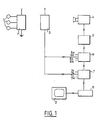
- the observation and recording device shown in FIG. 1 comprises three sensors 1 intended to be fixed to the thorax of a patient in order to detect the activity of his heart and to deliver electrical signals reflecting this activity.
- the sensors 1 are connected to a transmitter 2 powered by battery and carried by the patient, for example on the belt or on the back.
- the transmitter 2 is advantageously placed in a waterproof housing, which allows the patient who is provided to evolve in a swimming pool.
- the device according to the invention further comprises a receiver 3 of the signals emitted by the transmitter 2 and a television camera 4 intended to take pictures of the patient's progress, the behavior of the heart of which should be studied.
- the camera 4 which is advantageously of the automatic focusing type can be carried by an operator responsible for monitoring the developments patient.
- It can also be mounted on a tripod suitably placed in the patient's evolution zone and its movements can be controlled in azimuth and in elevation by a conventional device formed for example of a small radar set on the signals of one of the sensors 1 and controlling the corresponding servo electric motors.
- the output of the camera 4 is connected to the input of a video clock 5 intended to generate synchronization signals for the video signals.
- the video clock is also intended to provide indications of the date and time of the examination carried out. It also plays the role of a chronometer intended to make it possible to carry out calculations on recording portions of particular interest for the practitioner.
- the output of the video clock. 5 is connected to the input of a video frequency meter 6, the construction of which will be described in detail with reference to FIG. 2.
- the output of the video frequency counter is connected to the input of a video curve converter 7 which will be described in detail with reference to FIG. 4.
- the video frequency meter 6 and the video curve converter 7 each have an input by which they are connected to the output of the receiver 3 for cardiac activity signals.
- These two devices or at least one of them may include additional inputs making it possible to associate with the video signal relating to the image of the patient, information relating to the activity of other organs thereof or else to parameters of the environment in which it operates.
- These entries indicated in 6a to 6d and 7a to 7d in FIG. 1 can also receive heart signals from several patients or from athletes whose reactions to exercise are to be observed.
- the output of the video curve converter 7 is connected to the input of the video track of a video recorder 8, the playback output of which is connected to a screen display device 9.
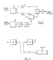
- the video frequency meter shown in Fig. 2 is intended to allow the display simultaneously with that of the image of the patient's evolution of encrypted information such as for example, the pulse rate, blood pressure, temperature or others.
- the video signal output of the circuit is connected via an amplifier 11 to an input of a mixer circuit 12.
- the synchronization signal output of circuit 10 is connected via an amplifier 13 to an input of a circuit 14 for reconstituting the composite signal.
- the video frequency meter further includes an input for the output signal from the receiver 3, signals reflecting the activity of the organ to be studied.
- This input is that of a converter 15 of analog signals into digital TTL signals further comprising a circuit for counting the received signals (not shown).
- the output of converter 15 is connected to the input of a circuit 16 for R, G, B component video coding of the color signal to be obtained.
- circuit 16 is connected to the input of a decoding circuit 16a, the output of which is in turn connected to another input of the mixer circuit 12.
- the output of the mixer circuit is connected to a second input of the circuit 14 for reconstituting the composite signal.
- circuit 14 The output of circuit 14 is connected via an amplifier 17 to the composite signal input of the video curve converter 7 (Fig. 1).
- the analog-digital converter 15 is connected to the recording input of an audio track of the video recorder 8, the playback output of the audio track of the latter being connected to the input of the video coding circuit.
- the audio track of the video recorder 8 constitutes a memory of the activity signals of the organ being monitored.
- These signals can be read in delayed time, in synchronism with the corresponding patient images.
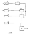
- the video curve converter shown in FIG. 4 comprises an analog input constituted by the input of an amplifier 20 of the output signals from the receiver 3.
- the output of the amplifier is connected to the input of an analog-digital converter 21 whose output is connected to the input of a decoder-comparator 22.
- the video curve converter also has a video input connected to the output of the video frequency meter 6 (Fig. 1).
- This video input is the input of a splitter 23 whose output is connected to the input of a video encoder 24.
- the function of the separator 23 is to eliminate the synchronization signal from the composite input signal.
- a local synchronization signal generator 25 has its output connected to the synchronization input of the comparator-decoder 22.
- the output of the comparator-decoder 22 is connected to an input of a signal mixer 26 which is further connected by another of its inputs to the output of a generator 27 of time interval signals, for example of a second.
- the output of the mixer 26 is connected to the corresponding input of the video recorder 8 and therefore constitutes the output of the video curve converter 7.
- the output of the amplifier 20 can be directly connected to a recording input on an audio track of the video recorder 8, the corresponding playback output of the latter then being connected to the input of the analog converter. digital 21.
- Such an arrangement allows direct recording of the signals reflecting the activity of the organ being monitored and a delayed reading of these signals in synchronism with the corresponding images showing the patient's progress.
- the device which has just been described operates in the following manner.
- This area can for example, a swimming pool in which the patient engages in swimming exercises.
- the camera which is either manipulated by an operator, or associated with a support with automatic pointing means on the patient, takes pictures of the patient's progress.
- the sensors 1 transmit to the transmitter 2, low frequency signals corresponding to the activity of the monitored organ.
- the transmitter 2 transmits these signals to the receiver 3.
- the output signals from the video camera 4 are applied to the input of the video clock 5 which delivers a composite signal at its output.
- This composite signal includes synchronization and timing video information, the latter allowing the practitioner to identify remarkable time intervals in the recording made in order to carry out detailed analyzes of the signals recorded during these intervals.
- the composite signal is applied to the input of the video frequency meter 6 which also receives the output signals from the receiver 3.
- the composite signal from the video clock 5 is separated into a video signal and a synchronization signal.
- the video signal amplified by the amplifier 11 is applied to the mixer circuit 12.
- the output signal from the receiver 3 is converted to digital and counted so that the digital output signal from the converter 15 corresponds to the instantaneous value of the number of heart pulses per unit of time.
- the output signal of the converter 15 is converted into an analog video signal in the digital-analog converter 16, decoded in the circuit 16a and applied to the mixer circuit 12.
- the latter delivers at its output a signal resulting from the superimposition of the video signals coming from the camera and resulting from the conversion of the output signals from the receiver 3 corresponding to the activity of the organ being monitored.
- This output signal is applied to an input of the circuit 14 for reconstituting a composite signal which receives at its other input the synchronization signal from the splitter 10.
- the output signal of circuit 14 constitutes, after amplification, the signal intended to be transmitted to the video curve converter 7.
- This signal contains the encrypted information relating to the patient's heart rate intended to be recorded by the video recorder 8 and to appear in clear on the display screen 9.
- This signal is in turn applied to the input of the video encoder 24.
- the output signal of said coder is applied to the corresponding input of comparator-decoder 22.
- the output signal from the transmitter 3 (Fig. 1) is applied to the input of the amplifier 20.
- this signal is converted into a digital TTL signal and applied to the corresponding input of the decoder comparator 22.
- the output signal from the comparator 22 contains both the information in video form, of the image of the patient during his activity, of the encrypted value of the heart rate and of the diagram as a function of the time of operation of the heart.
- This signal is made composite by means of the synchronization signal coming from the synchronization signal generator 25. It is applied to the signal mixer 26 which also receives a time interval signal generated by the generator 27.
- the mixer 26 distributes the signals of various kinds contained in the video signal and its output signal is applied to the video recorder 8 for recording, then to the display device 9.
- On the screen of the latter appear simultaneously the image of the patient in motion, the instantaneous numerical value of his heart rate, the date and time at which the recording takes place as well as the time diagram of the cardiac activity of the patient reported on a time scale of 1s appearing on the abscissa of this diagram.
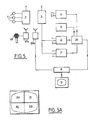
- Fig. 5 there is shown another embodiment of the device according to the invention.
- This device comprises sensors 1 connected to a transmitter 2 with autonomous supply carried by the patient.
- a receiver 3 for signals from the transmitter 2 is connected to a video frequency meter 6 and to a video curve converter 7.
- the device also comprises a video camera 4 and a video clock 5.
- the camera 4, the clock 5, the video frequency meter 6 and the video curve converter 7 are connected to corresponding inputs of an image cutting circuit 28.
- the cutter 28 distributes the various video information contained in the output signals of circuits 6 and 7 with a view to their display in corresponding areas of the screen of the associated display device 7 of the video recorder 8, to which the output of the chopper circuit 28 is connected.
- the device of FIG. 5 finally comprises a microphone 29 which the patient can carry with him to make comments on the sensations which he experiences during the examination.
- the microphone is connected to a transmitter 29a associated with an audio receiver 29b connected to an audio recording track of the video recorder 8 which records the information given by the patient simultaneously with the images of his activity.
- such a microphone associated with the corresponding transmission means can also be associated with the device of FIG. 1.
- FIG. 5A diagrams the surface of the screen of the display device 9.
- the upper left part 30 of the screen is reserved for displaying the image of the patient, the upper right part 31 is intended for displaying the numerical values of the heart rate, the time and other useful information. possibly coming from other inputs of the video frequency meter 6 which are then connected to data acquisition devices relating to this other encrypted information.
- the lower parts 32, 33 are provided for displaying the diagram as a function of the time of the activity of the heart.
- the sensors 1 are connected to a common transmitter 2.
- a transmitter with each sensor, which would make it possible, by miniaturizing these circuits, to avoid patient wearing a relatively bulky transmitter.
- this device can also be applied to the study of diseases, of organs other than the heart, provided that the activity of the organ concerned can be translated into recordable electrical signals.
- the invention can also be applied to the study of the behavior of high level athletes by taking into account factors of the environment in which they operate.
- the device according to the invention is designed for advanced miniaturization.
Landscapes
- Health & Medical Sciences (AREA)
- Life Sciences & Earth Sciences (AREA)
- General Health & Medical Sciences (AREA)
- Engineering & Computer Science (AREA)
- Medical Informatics (AREA)
- Animal Behavior & Ethology (AREA)
- Biophysics (AREA)
- Pathology (AREA)
- Biomedical Technology (AREA)
- Heart & Thoracic Surgery (AREA)
- Physical Education & Sports Medicine (AREA)
- Molecular Biology (AREA)
- Surgery (AREA)
- Physics & Mathematics (AREA)
- Physiology (AREA)
- Public Health (AREA)
- Veterinary Medicine (AREA)
- Cardiology (AREA)
- Computer Networks & Wireless Communication (AREA)
- Measuring And Recording Apparatus For Diagnosis (AREA)
- Measurement Of The Respiration, Hearing Ability, Form, And Blood Characteristics Of Living Organisms (AREA)
- Investigating Or Analysing Biological Materials (AREA)
Abstract
Description
La présente invention concerne un dispositif pour la détection, l'étude et la surveillance des maladies, notamment cardiaques qui se traduisent par des manifestations électriquement enregistrables.The present invention relates to a device for the detection, study and monitoring of diseases, in particular of the heart, which result in electrically recordable manifestations.
On sait que de nombreuses maladies ou malaises, (par exemple, les maladies cardiaques ou coronariennes) sont détectables par des détecteurs fournissant des informations électriquement enregistables (par exemple l'électrocardiogramme du patient).It is known that many diseases or ailments, (for example, cardiac or coronary diseases) are detectable by detectors providing electrically recordable information (for example the patient's electrocardiogram).
Mais on sait aussi que la détection de ces maladies, à leur stade le plus précoce, nécessite des enregistrements très prolongés et nécessite très souvent de connaître, à l'instant où les manifestations desdites maladies se font sentir, l'activité physique exacte des sujets surveillés.But we also know that the detection of these diseases, at their earliest stage, requires very prolonged recordings and very often requires knowing, at the moment when the manifestations of said diseases are felt, the exact physical activity of the subjects monitored.
Le brevet US. 4051 522 décrit un dispositif d'observation et d'enregistrement de l'activité d'au moins un organe du corps d'un patient se traduisant par des manifestations électriquement enregistrables, en vue notamment de l'étude et de la surveillance de maladies cardiaques.The US patent. 4051 522 describes a device for observing and recording the activity of at least one organ of the body of a patient resulting in electrically recordable manifestations, with a view in particular to the study and monitoring of heart diseases .
Ce dispositif comporte des moyens vidéo de prise de vue d'un patient, des moyens de détection et de transmission de signaux électriques traduisant l'activité de l'organe considéré, des moyens de combinaison des signaux vidéo correspondant à l'image du patient et des signaux électriques traduisant l'activité dudit organe, des moyens d'enregistrement desdits signaux combinés et des moyens d'affichage simultané des images relatives aux mouvements du patient et de celles des signaux électriques traduisant l'activité dudit organe.This device comprises video means for taking a picture of a patient, means for detecting and transmitting electrical signals reflecting the activity of the organ in question, means for combining video signals corresponding to the image of the patient and electrical signals reflecting the activity of said organ, means for recording said combined signals and means for simultaneously displaying images relating to the patient's movements and those of electrical signals reflecting the activity of said organ.
Les moyens de détection et de transmission des signaux traduisant l'activité dudit organe comprennent, des capteurs fixés au corps du patient de façon à recevoir les informations relatives à l'activité de cet organe et connectés à un émetteur porté par le patient et alimenté par une source d'énergie électrique autonome, et un récepteur des signaux de l'émetteur, ledit récepteur étant connecté à une entrée d'un convertisseur de courbe vidéo dont une autre entrée est connectée à la sortie desdits moyens de prise de vue, ledit convertisseur de courbe vidéo étant destiné à permettre l'enregistrement et/ou l'observation synchronisés des images relatives aux évolutions du patient prises par les moyens de prise de vue et celle du diagramme en fonction du temps du fonctionnement de l'organe considéré, ledit récepteur étant en outre connecté à une entrée d'un fréquencemètre vidéo dont une autre entrée est connectée à la sortie desdits moyens de prise de vue, ledit fréquencemètre vidéo étant destiné à permettre l'enregistrement et/ou l'observation synchronisés des images relatives aux évolutions du patient prises par les moyens de prise de vue et les images d'informations chiffrées relatives au fonctionnement de l'organe considéré.The means for detecting and transmitting the signals reflecting the activity of said organ include, sensors fixed to the patient's body so as to receive information relating to the activity of this organ and connected to a transmitter carried by the patient and powered by an autonomous electric power source, and a receiver of the transmitter signals, said receiver being connected to an input of a video curve converter, another input of which is connected to the output of said shooting means, said converter of video curve being intended to allow the recording and / or the synchronized observation of the images relating to the evolutions of the patient taken by the shooting means and that of the diagram as a function of the time of operation of the organ considered, said receiver being further connected to an input of a video frequency meter of which another input is connected to the output of said shooting means, said video frequency meter being intended to allow the synchronized recording and / or observation of the images relating to the changes in the patient taken by the shooting means and the images of encrypted information relating to the functioning of the organ considered.
Le but de la présente invention est de mettre à la disposition des médecins et chercheurs médicaux, un dispositif du type précité permettant de détecter dans les meilleures conditions et en rassemblant les divers éléments nécessaires, les maladies qui peuvent se traduire par une manifestation électriquement enregistrable.The purpose of the present invention is to make available to doctors and medical researchers, a device of the aforementioned type making it possible to detect under the best conditions and by gathering the various necessary elements, the diseases which can result in an electrically recordable manifestation.
L'invention a donc pour objet un dispositif d'observation et d'enregistrement de l'activité d'au moins un organe du corps d'un patient se traduisant par des manifestations électriquement enregistrables, en vue notamment de l'étude et de la surveillance de maladies cardiaques, comportant des moyens vidéo de prise de vue des mouvements du patient, des moyens de détection et de transmission de signaux électriques traduisant l'activité de l'organe considéré, comprenant, comme connu en soi, des capteurs fixés au corps du patient de façon à recevoir les informations relatives à l'activité de cet organe et connectés à un émetteur de télémétrie porté par le patient et un récepteur de télémétrie, des moyens de conversion et de combinaison des signaux vidéo relatifs aux évolutions du patient prises par les moyens de prise de vue avec des images d'informations chiffrées relatives au fonctionnement de l'organe considéré et des images du diagramme en fonction du temps de signaux électriques traduisant l'activité dudit organe, des moyens d'enregistrement desdits signaux combinés et des moyens d'affichage simultané des images relatives aux mouvements du patient, des images d'informations chiffrées et des images du diagramme en fonction du temps des signaux électriques traduisant l'activité dudit organe, caractérisé en ce qu'un fréquencemètre vidéo destiné à permettre l'enregistrement et/ou l'observation synchronisés des images relatives aux évolutions du patient prises par les moyens de prise de vue et des images d'informations chiffrées relatives au fonctionnement de l'organe considéré comprend au moins une entrée destinée à recevoir les signaux électriques traduisant l'activité de l'organe du patient connectée à une sortie du récepteur, une autre entrée destinée à recevoir un signal vidéo et de synchronisation connectée via une horloge vidéo à la sortie des moyens de prise de vue et une sortie connectée à une entrée de signal composite d'un convertisseur de courbe vidéo destiné à permettre l'enregistrement et/ou l'observation synchronisés des images relatives aux évolutions du patient et celles du diagramme en fonction du temps de signaux électriques traduisant l'activité dudit organe et comprenant au moins une autre entrée destinée à recevoir les signaux électriques traduisant l'activité de l'organe du patient, connectée à la sortie du récepteur et une sortie connectée aux moyens d'enregistrement vidéo et aux moyens de visualisation.The subject of the invention is therefore a device for observing and recording the activity of at least one organ of the body of a patient resulting in electrically recordable manifestations, with a view in particular to the study and the monitoring of cardiac diseases, comprising video means of recording the movements of the patient, means of detection and transmission of electrical signals reflecting the activity of the organ under consideration, comprising, as known per se, sensors fixed to the body of the patient so as to receive information relating to the activity of this organ and connected to a telemetry transmitter carried by the patient and a telemetry receiver, means for converting and combining video signals relating to the progress of the patient taken by the means of shooting with images of encrypted information relating to the operation of the organ considered and images of the diagram as a function of time of translated electrical signals ant the activity of said organ, means for recording said combined signals and means for simultaneously displaying images relating to the patient's movements, images of encrypted information and images of the diagram as a function of time of the electrical signals translating the activity of said organ, characterized in that a video frequency counter intended to allow the synchronized recording and / or observation of images relating to changes in the patient taken by the shooting means and images of encrypted information relating to the operation of the organ considered comprises at least one input intended to receive the electrical signals translating the activity of the patient's organ connected to an output of the receiver, another input intended to receive a video and synchronization signal connected via a clock video at the output of the shooting means and an output connected to a composite signal input of a video curve converter intended to allow the synchronized recording and / or observation of the images relating to the patient's progress and those of the diagram as a function of time of electrical signals reflecting the activity of said organ and comprising at least one other input intended to receive the electrical signals translating the activity of the patient's organ, connected to the output of the receiver and an output connected to the video recording means and to the viewing means.
Un second mode de réalisation du dispositif selon l'invention est caractérisé en ce qu'un découpeur d'image (28) assurant la répartition des diverses informations vidéo en vue de leur affichage dans des zones correspondantes des moyens (9) d'affichage comprend une première entrée connectée à la sortie d'un fréquencemètre vidéo, (6) recevant sur au moins une entrée (6a, b, c, d) connectée à la sortie du récepteur (3) des signaux électriques traduisant l'activité dudit organe, une deuxième entrée connectée à la sortie d'un convertisseur de courbe vidéo (7) recevant sur au moins une entrée (7a, b, c, d) connectée à la sortie du récepteur (3) des signaux électriques traduisant l'activité dudit organe, une troisième entrée connectée à la sortie des moyens (4) de prise de vue, une quatrième entrée connectée à la sortie d'une horloge vidéo (5) et une sortie connectée auxdits moyens (8) d'enregistrement vidéo et moyens (9) d'affichage vidéo en vue de l'enregistrement et/ou l'affichage simultanés des images provenant des moyens (4) de prise de vue, des images d'informations chiffrées provenant du fréquencemètre vidéo (6), des images du diagramme en fonction du temps provenant du convertisseur de courbe vidéo (7) et des images provenant de l'horloge vidéo (5) dans des zones indépendantes et correspondantes de l'image vidéo.A second embodiment of the device according to the invention is characterized in that a image cutter (28) distributing the various video information with a view to displaying it in corresponding areas of the display means (9) comprises a first input connected to the output of a video frequency counter, (6) receiving on at least one input (6a, b, c, d) connected to the output of the receiver (3) of the electrical signals reflecting the activity of said organ, a second input connected to the output of a video curve converter (7) receiving on at least one input (7a, b, c, d) connected to the output of the receiver (3) of the electrical signals translating the activity of said organ, a third input connected to the output of the means of shooting (4), a fourth input connected to the output of a video clock (5) and an output connected to said video recording means (8) and video display means (9) for simultaneous recording and / or display images from the shooting means (4), images of encrypted information s from the video frequency meter (6), images of the diagram as a function of time from the video curve converter (7) and images from the video clock (5) in independent and corresponding areas of the video image.
Si les moyens qui constituent le dispositif selon l'invention peuvent être matériellement reliés les uns aux autres, l'invention se révèle tout spécialement intéressante lorsque le sujet à étudier a une indépendance totale dans ses exercices et ses déplacements, ce qui implique le plus souvent qu'il convient de prévoir des moyens permettant la transmission à distance des informations recueillies notamment en ce qui concerne l'électrocardiogramme qui sera transmis vers un appareil récepteur et éventuellement enregistreur du type appareil de télévision et magnétoscope.If the means which constitute the device according to the invention can be materially connected to each other, the invention proves to be particularly interesting when the subject to be studied has complete independence in his exercises and his movements, which most often involves that means should be provided for the remote transmission of information collected in particular with regard to the electrocardiogram which will be transmitted to a receiving and possibly recording device of the television and video recorder type.
Il est clair également que, si dans certains cas, il apparaît nécessaire de recueillir simultanément, outre l'image de patient et son électrocardiogramme, des informations complémentaires, telles que température, état de la peau, etc. il est possible dans le cadre de l'invention de mettre sur le patient un détecteur approprié permettant de recueillir l'information souhaitée et de transmettre cette information à l'assembleur utilisé dans l'invention.It is also clear that, in certain cases, it appears necessary to collect simultaneously, in addition to the patient image and his electrocardiogram, additional information, such as temperature, skin condition, etc. it is possible within the framework of the invention to put on the patient an appropriate detector making it possible to collect the desired information and to transmit this information to the assembler used in the invention.
Comme moyens vidéo suiveurs, on utilise un système vidéomagnétoscopique constitué essentiellement d'une petite caméra ayant un système de stockage des images filmées. Cette caméra est montée sur un pied pivotant. l'orientation de cette caméra (sur le patient) est réalisée grâce à un émetteur fixé sur 1, patient qui commande à un ou plusieurs moteurs asservis, lesquels orientent constamment la caméra sur le patient émetteur. Cette caméra enregistrera sur une portion du film (par exemple une moitié de ce film) les déplacements et les gestes du patient.As video tracking means, a videomagnetoscopic system consisting essentially of a small camera having a system for storing filmed images is used. This camera is mounted on a swivel stand. the orientation of this camera (on the patient) is carried out by means of a transmitter fixed on 1, patient who controls one or more slave motors, which constantly orient the camera on the patient transmitter. This camera will record on a portion of the film (for example half of this film) the movements and gestures of the patient.
Les moyens de détection des pulsations du coeur sont connus, on utilise le plus souvent deux ou trois électrodes fixées sur le thorax du patient qui recueillent les potentiels d'action cardiaque émis tout au long des battements ces électrodes sont reliées à un boîtier de petite taille porté à la ceinture du patient qui enregistre l'électrocardiogramme et le transmet à la caméra décrite ci-dessus, de façon que cette dernière enregistre à son tour ledit électrocardiogramme sur le même film qui enregistre simultanément l'activité du patient. Ce boîtier est de préférence totalement étanche car il est souvent souhaitable d'utiliser le dispositif de l'invention lorsque le patient effectue des mouvements de natation. Les progrès de l'électronique permettent aujourd'hui d'envisager la suppression dudit boîtier et l'émission directe vers la caméra, en vue de l'enregistrement, des informations recueillies par chaque électrode, informations qui formeront l'électrocardiogramme du patient.The means for detecting the pulsations of the heart are known, most often two or three electrodes fixed on the patient's chest are used which collect the cardiac action potentials emitted throughout the beats. These electrodes are connected to a small box. worn on the patient's belt which records the electrocardiogram and transmits it to the camera described above, so that the latter in turn records said electrocardiogram on the same film which simultaneously records the activity of the patient. This housing is preferably completely waterproof because it is often desirable to use the device of the invention when the patient performs swimming movements. Advances in electronics now make it possible to envisage the removal of said box and the direct transmission to the camera, for the purpose of recording, of the information collected by each electrode, information which will form the patient's electrocardiogram.
L'assembleur est, selon l'invention, constitué par la caméra elle-même ou son film qui recueille simultanément les informations, image et électrocardiogramme ; ce film est projeté et il est alors possible d'apprécier simultanément la forme et l'intensité d'un mouvement et les modifications induites par ce mouvement sur l'électrocardiogramme.The assembler is, according to the invention, constituted by the camera itself or its film which simultaneously collects the information, image and electrocardiogram; this film is projected and it is then possible to appreciate simultaneously the shape and the intensity of a movement and the modifications induced by this movement on the electrocardiogram.
L'invention sera mieux comprise à l'aide de la description qui va suivre, donnée uniquement à titre d'exemple et faite en se référant aux dessins annexés, sur lesquels :
- - la Fig. 1 est un schéma synoptique d'un mode de réalisation préféré du dispositif d'observation et d'enregistrement suivant l'invention ;
- - la Fig. 2 est un schéma plus détaillé du fréquencemètre vidéo entrant dans la construc- tion du dispositif de la Fig. 1 ;
- - la Fig. 3 est un schéma partiel montrant une variante du fréquencemètre vidéo de la Fig. 2 ;
- - la Fig. 4 est un schéma détaillé du dispositif convertisseur de courbe vidéo entrant dans la construction du dispositif de la Fig. 1 ;
- - la Fig. 5 est un schéma synoptique d'un autre mode de réalisation du dispositif d'observation et d'enregistrement de la Fig. 1 ; et
- - la Fig. 5A montre le découpage de l'écran du dispositif d'affichage de la Fig. 5.
- - Fig. 1 is a block diagram of a preferred embodiment of the observation and recording device according to the invention;
- - Fig. 2 is a more detailed diagram of the frequency video entering the construc - tion of the device of Fig. 1;
- - Fig. 3 is a partial diagram showing a variant of the video frequency counter in FIG. 2;
- - Fig. 4 is a detailed diagram of the video curve converter device used in the construction of the device of FIG. 1;
- - Fig. 5 is a block diagram of another embodiment of the observation and recording device of FIG. 1; and
- - Fig. 5A shows the cutting of the screen of the display device of FIG. 5.
Le dispositif d'observation et d'enregistrement représenté à la Fig. 1 comporte trois capteurs 1 destinés à être fixés au thorax d'un patient en vue de détecter l'activité de son coeur et de délivrer des signaux électriques traduisant cette activité.The observation and recording device shown in FIG. 1 comprises three sensors 1 intended to be fixed to the thorax of a patient in order to detect the activity of his heart and to deliver electrical signals reflecting this activity.
Les capteurs 1 sont connectés à un émetteur 2 alimenté par batterie et porté par le patient, par exemple à la ceinture ou sur le dos.The sensors 1 are connected to a
L'émetteur 2 est avantageusement placé dans un boîtier étanche, ce qui permet au patient qui en est muni d'évoluer dans une piscine.The
Le dispositif suivant l'invention comporte en outre un récepteur 3 des signaux émis par l'émetteur 2 et une caméra de télévision 4 destinée à effectuer des prises de vue des évolutions du patient dont il y a lieu d'étudier le comportement du coeur.The device according to the invention further comprises a
La caméra 4 qui est avantageusement du type à focalisation automatique peut être portée par un opérateur chargé de suivre les évolutions du patient.The
Elle peut être également montée sur un trépied convenablement disposé dans la zone d'évolution du patient et ses mouvements peuvent être commandés en azimut et en site par un dispositif classique formé par exemple d'un petit radar calé sur les signaux de l'un des capteurs 1 et commandant des moteurs électriques asservis correspondants.It can also be mounted on a tripod suitably placed in the patient's evolution zone and its movements can be controlled in azimuth and in elevation by a conventional device formed for example of a small radar set on the signals of one of the sensors 1 and controlling the corresponding servo electric motors.
La sortie de la caméra 4 est connectée à l'entrée d'une horloge vidéo 5 destinée à générer des signaux de synchronisation pour les signaux vidéo. L'horloge vidéo est en outre destinée à fournir des indications de date et d'heure de l'examen effectué. Elle joue également le rôle de chronomètre destiné à permettre d'effectuer des calculs sur des portions d'enregistrement d'un intérêt particulier pour le praticien.The output of the
La sortie de l'horloge vidéo.5 est connectée à l'entrée d'un fréquencemètre vidéo 6 dont la constitution va être décrite en détail en référence à la Fig. 2.The output of the video clock. 5 is connected to the input of a
La sortie du fréquencemètre vidéo est connectée à l'entrée d'un convertisseur de courbe vidéo' 7 qui sera décrit en détail en référence à la Fig. 4.The output of the video frequency counter is connected to the input of a
Le fréquencemètre vidéo 6 et le convertisseur de courbe vidéo 7 comportent chacun une entrée par laquelle ils sont connectés à la sortie du récepteur 3 des signaux d'activité cardiaque.The
Ces deux dispositifs ou l'un d'entre eux au moins peuvent comporter des entrées supplémentaires permettant d'associer au signal vidéo relatif à l'image du patient, des informations relatives à l'activité d'autres organes de celui-ci ou encore à des paramètres de l'environnement dans lequel il évolue.These two devices or at least one of them may include additional inputs making it possible to associate with the video signal relating to the image of the patient, information relating to the activity of other organs thereof or else to parameters of the environment in which it operates.
Ces entrées indiquées en 6a à 6d et 7a à 7d à la Fig. 1 peuvent également recevoir les signaux cardiaques de plusieurs patients ou encore d'athlètes dont on souhaite observer les réactions à l'effort.These entries indicated in 6a to 6d and 7a to 7d in FIG. 1 can also receive heart signals from several patients or from athletes whose reactions to exercise are to be observed.
La sortie du convertisseur de courbe vidéo 7 est connectée à l'entrée de la piste vidéo d'un magnétoscope 8 dont la sortie de lecture est connectée a un dispositif d'affichage à écran 9.The output of the
Bien entendu, il est également possible de connecter le dispositif d'affichage 9 directement à la sortie du convertisseur de courbe vidéo 7. Dans ce cas, on ne disposera que d'informations en temps réel sur l'activité du patient et sur les réactions du ou des organes étudiés de celui-ci.Of course, it is also possible to connect the
Le fréquencemètre vidéo représenté à la Fig. 2, est destiné à permettre l'affichage simultanément avec celui de l'image des évolutions du patient d'informations chiffrées telles que par exemple, la cadence du pouls, la tension artérielle, la température ou autres.The video frequency meter shown in Fig. 2, is intended to allow the display simultaneously with that of the image of the patient's evolution of encrypted information such as for example, the pulse rate, blood pressure, temperature or others.
Il comprend principalement un circuit 10 destiné à assurer la séparation des signaux vidéo et de synchronisation qui composent le signal de sortie de l'horloge vidéo 5 (Fig. 1).It mainly comprises a
La sortie de signal vidéo du circuit est connectée par l'intermédiaire d'un amplificateur 11 à une entrée d'un circuit mélangeur 12.The video signal output of the circuit is connected via an
La sortie de signal de synchronisation du circuit 10 est connectée par l'intermédiaire d'un amplificateur 13 à une entrée d'un circuit 14 de reconstitution du signal composite.The synchronization signal output of
Le fréquencemètre vidéo comporte en outre une entrée pour le signal de sortie du récepteur 3, des signaux traduisant l'activité de l'organe à étudier.The video frequency meter further includes an input for the output signal from the
Cette entrée est celle d'un convertisseur 15 de signaux analogiques en signaux numériques TTL comportant en outre un circuit de comptage des signaux reçus (non représentés).This input is that of a
La sortie du convertisseur 15 est connectée à l'entrée d'un circuit 16 de codage vidéo en composantes R, V, B du signal en couleur à obtenir.The output of
La sortie du circuit 16 est connectée à l'entrée d'un circuit 16a de décodage dont la sortie est reliée à son tour à une autre entrée du circuit mélangeur 12.The output of
La sortie du circuit mélangeur est reliée à une seconde entrée du circuit 14 de reconstitution du signal composite.The output of the mixer circuit is connected to a second input of the
La sortie du circuit 14 est connectée par l'intermédiaire d'un amplificateur 17 à l'entrée de signal composite du convertisseur de courbe vidéo 7 (Fig. 1).The output of
Selon une variante représentée à la Fig. 3, le convertisseur analogique-numérique 15 est connecté à l'entrée d'enregistrement d'une piste audio du magnétoscope 8, la sortie lecture de la piste audio de ce dernier étant reliée à l'entrée du circuit de codage vidéo.According to a variant shown in FIG. 3, the analog-
Dans ce cas, la piste audio du magnétoscope 8 constitue une mémoire des signaux d'activité de t'organe surveillé.In this case, the audio track of the
La lecture de ces signaux pourra être faite en temps différé, en synchronisme avec les images correspondantes du patient.These signals can be read in delayed time, in synchronism with the corresponding patient images.
Le convertisseur de courbe vidéo représenté à la Fig. 4 comporte une entrée analogique constituée par l'entrée d'un amplificateur 20 des signaux de sortie du récepteur 3. La sortie de l'amplificateur est connectée à l'entrée d'un convertisseur analogique-numérique 21 dont la sortie est reliée à l'entrée d'un décodeur-comparateur 22.The video curve converter shown in FIG. 4 comprises an analog input constituted by the input of an
Le convertisseur de courbe vidéo comporte en outre une entrée vidéo connectée à la sortie du fréquencemètre vidéo 6 (Fig. 1).The video curve converter also has a video input connected to the output of the video frequency meter 6 (Fig. 1).
Cette entrée vidéo est l'entrée d'un séparateur 23 dont la sortie est connectée à l'entrée d'un codeur vidéo 24.This video input is the input of a
Le séparateur 23 a pour fonction d'éliminer le signal de synchronisation du signal composite d'entrée.The function of the
Un générateur de signaux de synchronisation local 25 a sa sortie connectée à l'entrée de synchronisation du comparateur-décodeur 22.A local
La sortie du comparateur-décodeur 22 est connectée à une entrée d'un mélangeur de signaux 26 qui est en outre connecté par une autre de ses entrées à la sortie d'un générateur 27 de signaux d'intervalles de temps, par exemple d'une seconde.The output of the comparator-
La sortie du mélangeur 26 est connectée à l'entrée correspondante du magnétoscope 8 et constitue donc la sortie du convertisseur de courbes vidéo 7.The output of the
A titre de variante, la sortie de l'amplificateur 20 peut être connectée directement à une entrée d'enregistrement sur une piste audio du magnétoscope 8, la sortie de lecture correspondante de celui-ci étant alors reliée à l'entrée du convertisseur analogique-numérique 21. Un tel agencement permet un enregistrement direct des signaux traduisant l'activité de l'organe surveillé et une lecture différée de ces signaux en synchronisme avec les images correspondantes montrant les évolutions du patient.As a variant, the output of the
Le dispositif qui vient d'être décrit fonctionne de la façon suivante.The device which has just been described operates in the following manner.
Le patient qui porte sur lui les capteurs 1 convenablement disposés par rapport à l'organe à surveiller, par exemple le coeur, ainsi que l'émetteur 2, évolue dans une zone se trouvant dans le champ de la caméra vidéo 4. Cette zone peut être par exemple une piscine dans laquelle le patient se livre à des exercices de natation.The patient who carries with him the sensors 1 suitably arranged with respect to the organ to be monitored, for example the heart, as well as the
La caméra qui est soit manipulée par un opérateur, soit associée à un support avec des moyens de pointage automatique sur le patient, effectue des prises de vue des évolutions de celui-ci.The camera which is either manipulated by an operator, or associated with a support with automatic pointing means on the patient, takes pictures of the patient's progress.
Simultanément, les capteurs 1 transmettent à l'émetteur 2, des signaux à basse fréquence correspondant à l'activité'de l'organe surveillé.Simultaneously, the sensors 1 transmit to the
L'émetteur 2 transmet ces signaux au récepteur 3.The
Les signaux de sortie de la caméra vidéo 4 sont appliqués à l'entrée de l'horloge vidéo 5 qui délivre à sa sortie un signal composite. Ce signal composite comporte des informations vidéo de synchronisation et chronométriques, ces dernières permettant au praticien de repérer des intervalles de temps remarquables dans l'enregistrement effectué en vue de procéder à des analyses détaillées des signaux enregistrés pendant ces intervalles. Le signal composite est appliqué à l'entrée du fréquencemètre vidéo 6 qui reçoit également les signaux de sortie du récepteur 3.The output signals from the
Dans le fréquencemètre vidéo 6, le signal composite provenant de l'horloge vidéo 5 est séparé en un signal vidéo et un signal de synchronisation. Le signal vidéo amplifié par l'amplificateur 11 est appliqué au circuit mélangeur 12.In the
Le signal de sortie du récepteur 3 est converti en numérique et compté de sorte que le signal numérique de sortie du convertisseur 15 correspond à la valeur instantanée du nombre de pulsations du coeur par unité de temps.The output signal from the
Le signal de sortie du convertisseur 15 est converti en signal analogique vidéo dans le convertisseur numérique-analogique 16, décodé dans le circuit 16a et appliqué au circuit mélangeur 12.The output signal of the
Celui-ci délivre à sa sortie un signal résultant de la superposition des signaux vidéo en provenance de la caméra et résultant de la conversion des signaux de sortie du récepteur 3 correspondant à l'activité de l'organe surveillé.The latter delivers at its output a signal resulting from the superimposition of the video signals coming from the camera and resulting from the conversion of the output signals from the
Ce signal de sortie est appliqué à une entrée du circuit 14 de reconstitution d'un signal composite qui reçoit à son autre entrée le signal de synchronisation à partir du séparateur 10.This output signal is applied to an input of the
Le signal de sortie du circuit 14 constitue après amplification, le signal destiné à être transmis au convertisseur de courbe vidéo 7.The output signal of
Ce signal contient les informations chiffrées relatives au rythme cardiaque du patient destinées à être enregistrées par le magnétoscope 8 et à apparaître en clair sur l'écran d'affichage 9.This signal contains the encrypted information relating to the patient's heart rate intended to be recorded by the
Il est appliqué à l'entrée du circuit séparateur 23 dont le signal de sortie ne comporte que le signal vidéo seul.It is applied to the input of the
Ce signal est à son tour appliqué à l'entrée du codeur vidéo 24.This signal is in turn applied to the input of the
Le signal de sortie dudit codeur est appliqué à l'entrée correspondante du comparateur-décodeur 22.The output signal of said coder is applied to the corresponding input of comparator-
Le signal de sortie de l'émetteur 3 (Fig.1) est appliqué à l'entrée de l'amplificateur 20.The output signal from the transmitter 3 (Fig. 1) is applied to the input of the
Après amplification, ce signal est converti en signal numérique TTL et appliqué à l'entrée correspondante du comparateur décodeur 22.After amplification, this signal is converted into a digital TTL signal and applied to the corresponding input of the
Le signal de sortie du comparateur 22 contient à la fois les informations sous forme vidéo, de l'image du patient au cours de son activité, de la valeur chiffrée du rythme cardiaque et du diagramme en fonction du temps du fonctionnement du coeur.The output signal from the
Ce signal est rendu composite au moyen du signal de synchronisation provenant du générateur de signaux de synchronisation 25. Il est appliqué au mélangeur de signaux 26 qui reçoit en outre un signal d'intervalle de temps généré par le générateur 27.This signal is made composite by means of the synchronization signal coming from the
Le mélangeur 26 assure une répartition des signaux de diverses natures contenus dans le signal vidéo et son signal de sortie est appliqué au magnétoscope 8 en vue d'être enregistré, puis au dispositif d'affichage 9. Sur l'écran de ce dernier apparaissent simultanément l'image du patient en mouvement, la valeur chiffrée instantanée de son rythme cardiaque, la date et l'heure à laquelle l'enregistrement a lieu ainsi que le diagramme temporel de l'activité cardiaque du patient rapporté à une échelle de temps de 1s apparaissant en abcisse de ce diagramme.The
A la Fig. 5, on a représenté un autre mode de réalisation du dispositif suivant l'invention.In Fig. 5, there is shown another embodiment of the device according to the invention.
Sur cette figure, les éléments du dispositif identiques à ceux des dispositifs de la Fig.1 sont désignés par les mêmes numéros de référence.In this figure, the elements of the device identical to those of the devices of Fig.1 are designated by the same reference numbers.
Ce dispositif comporte des capteurs 1 connectés à un émetteur 2 à alimentation autonome porté par le patient. Un récepteur 3 des signaux de l'émetteur 2 est connecté a un fréquencemètre vidéo 6 et à un convertisseur de courbe vidéo 7.This device comprises sensors 1 connected to a
Le dispositif comporte en outre une caméra vidéo 4 et une horloge vidéo 5.The device also comprises a
La caméra 4, l'horloge 5, le fréquencemètre vidéo 6 et le convertisseur de courbe vidéo 7 sont connectés à des entrées correspondantes d'un circuit découpeur d'image 28.The
Le découpeur 28 assure la répartition des diverses informations vidéo contenues dans les signaux de sortie des circuits 6 et 7 en vue de leur affichage dans des zones correspondantes de l'écran du dispositif d'affichage 7 associé du magnétoscope 8, auquel est connectée la sortie du circuit découpeur 28.The
Le dispositif de la Fig. 5 comporte enfin un microphone 29 que le patient peut porter sur lui pour faire des commentaires sur les sensations qu'il éprouve au cours de l'examen.The device of FIG. 5 finally comprises a
Le microphone est connecté à un émetteur 29a associé à un récepteur audio 29b connecté à une piste d'enregistrement audio du magnétoscope 8 qui enregistre les informations données par le patient simultanément avec les images de son activité.The microphone is connected to a
Lors de la lecture, ces informations peuvent être utiles pour compléter l'analyse du praticien.When reading, this information can be useful to complete the practitioner's analysis.
Bien entendu, un tel microphone associé aux moyens de transmission correspondants peut également être associé au dispositif de la Fig.1.Of course, such a microphone associated with the corresponding transmission means can also be associated with the device of FIG. 1.
La répartition assurée par le découpeur 28 est représentée à la Fig. 5A qui schématise la surface de l'écran du dispositif d'affichage 9.The distribution provided by the
La partie supérieure gauche 30 de l'écran est réservée à l'affichage de l'image du patient, la partie supérieure droite 31 est destinée à l'affichage des valeurs chiffrées du rythme cardiaque, de l'heure et d'autres informations utiles provenant éventuellement d'autres entrées du fréquencemètre vidéo 6 qui sont alors connectées à des dispositifs d'acquisition de données relatives à ces autres informations chiffrées.The upper
Les parties inférieures 32, 33 sont prévues pour l'affichage du diagramme en fonction du temps de l'activité du coeur.The
Dans les modes de réalisation qui viennent d'être décrits, les capteurs 1 sont connectés à un émetteur commun 2. On peut cependant envisager d'associer un émetteur à chaque capteur, ce qui permettrait moyennant une miniaturisation de ces circuits, d'éviter au patient le port d'un émetteur relativement encombrant.In the embodiments which have just been described, the sensors 1 are connected to a
Les modes de réalisation qui viennent d'être décrits sont considérés comme étant appliqués à l'observation et à l'enregistrement de phénomènes cardiologiques en vue de l'étude et de la surveillance de maladies cardiaques.The embodiments which have just been described are considered to be applied to the observation and recording of cardiological phenomena with a view to the study and monitoring of heart diseases.
On comprendra cependant que ce dispositif peut également être appliqué à l'étude de maladies, d'autres organes que le coeur, à condition que l'activité de l'organe concerné puisse être traduite en signaux électriques enregistrables.It will however be understood that this device can also be applied to the study of diseases, of organs other than the heart, provided that the activity of the organ concerned can be translated into recordable electrical signals.
L'invention peut également s'appliquer à l'étude du comportement de sportifs de haut niveau en tenant compte de facteurs de l'environnement dans lequel ils évoluent.The invention can also be applied to the study of the behavior of high level athletes by taking into account factors of the environment in which they operate.
Le dispositif suivant l'invention est conçu pour une miniaturisation poussée.The device according to the invention is designed for advanced miniaturization.
Il est par exemple possible d'intégrer à la caméra, le récepteur 3, l'horloge 5, le fréquencemètre vidéo 6 et le convertisseur vidéo 7.It is for example possible to integrate into the camera, the
Claims (10)
Priority Applications (1)
| Application Number | Priority Date | Filing Date | Title |
|---|---|---|---|
| AT86400739T ATE36947T1 (en) | 1985-04-09 | 1986-04-07 | DEVICE FOR OBSERVING PEOPLE, PARTICULARLY PEOPLE WITH HEART DISEASES, BY MEANS OF ELECTRICALLY STORABLE MEASURING PARAMETERS. |
Applications Claiming Priority (2)
| Application Number | Priority Date | Filing Date | Title |
|---|---|---|---|
| MA20630A MA20406A1 (en) | 1985-04-09 | 1985-04-09 | DEVICE FOR THE DETECTION, STUDY AND MONITORING OF DISEASES, ESPECIALLY CARDIAC, TRANSLATED BY ELECTRICALLY RECORDABLE MANIFESTATIONS |
| MA20630 | 1985-04-09 |
Publications (2)
| Publication Number | Publication Date |
|---|---|
| EP0200610A1 EP0200610A1 (en) | 1986-12-10 |
| EP0200610B1 true EP0200610B1 (en) | 1988-09-07 |
Family
ID=32292257
Family Applications (1)
| Application Number | Title | Priority Date | Filing Date |
|---|---|---|---|
| EP86400739A Expired EP0200610B1 (en) | 1985-04-09 | 1986-04-07 | Device for monitoring persons, in particular cardiac patients, by means of data to be electrically recorded |
Country Status (6)
| Country | Link |
|---|---|
| US (1) | US4805631A (en) |
| EP (1) | EP0200610B1 (en) |
| AT (1) | ATE36947T1 (en) |
| DE (1) | DE3660648D1 (en) |
| FR (1) | FR2579885B1 (en) |
| MA (1) | MA20406A1 (en) |
Families Citing this family (30)
| Publication number | Priority date | Publication date | Assignee | Title |
|---|---|---|---|---|
| US4914686A (en) * | 1986-11-28 | 1990-04-03 | Hagar Iii William G | Cordless phone data logger |
| GB2221536A (en) * | 1988-07-26 | 1990-02-07 | Dayton Ind Company Limited | Cycle computer |
| US5321800A (en) * | 1989-11-24 | 1994-06-14 | Lesser Michael F | Graphical language methodology for information display |
| US5441047A (en) * | 1992-03-25 | 1995-08-15 | David; Daniel | Ambulatory patient health monitoring techniques utilizing interactive visual communication |
| AT401451B (en) * | 1992-04-23 | 1996-09-25 | Eric Holzer | VIDEO CAMERA |
| US5271106A (en) * | 1992-10-06 | 1993-12-21 | Mcclish Richard E D | Emulative swimming pool |
| US5527239A (en) * | 1993-02-04 | 1996-06-18 | Abbondanza; James M. | Pulse rate controlled exercise system |
| DE4329898A1 (en) | 1993-09-04 | 1995-04-06 | Marcus Dr Besson | Wireless medical diagnostic and monitoring device |
| US5890906A (en) * | 1995-01-20 | 1999-04-06 | Vincent J. Macri | Method and apparatus for tutorial, self and assisted instruction directed to simulated preparation, training and competitive play and entertainment |
| US5647747A (en) * | 1995-01-20 | 1997-07-15 | Vincent J. Macri | Mechanized robots for use in instruction, training, and practice in the sport of ice and roller hockey |
| US5643094A (en) * | 1995-01-20 | 1997-07-01 | Macri; Vincent J. | Interactive ice and roller hockey training, coaching, and playing rinks |
| EP0804265B1 (en) * | 1995-01-20 | 2000-04-05 | Vincent J. Macri | Instruction for playing hockey |
| DE19516451C2 (en) * | 1995-05-04 | 1999-08-12 | Sirona Dental Systems Gmbh | Diagnostic device with a mobile signal recording device and a stationary evaluation device |
| US6220865B1 (en) | 1996-01-22 | 2001-04-24 | Vincent J. Macri | Instruction for groups of users interactively controlling groups of images to make idiosyncratic, simulated, physical movements |
| US5842978A (en) * | 1996-11-18 | 1998-12-01 | Levy; Itchak | Supplemental audio visual emergency reviewing apparatus and method |
| AU8677098A (en) | 1997-07-31 | 1999-02-22 | Case Western Reserve University | A system and method for non-invasive electrocardiographic imaging |
| US6975900B2 (en) * | 1997-07-31 | 2005-12-13 | Case Western Reserve University | Systems and methods for determining a surface geometry |
| US6839588B1 (en) | 1997-07-31 | 2005-01-04 | Case Western Reserve University | Electrophysiological cardiac mapping system based on a non-contact non-expandable miniature multi-electrode catheter and method therefor |
| US5887577A (en) | 1997-11-04 | 1999-03-30 | Sherrill; William T. | Apparatus for propelling a projectile |
| US6086379A (en) * | 1998-10-20 | 2000-07-11 | Research Foundation Of State University Of New York | System and method for training a swimmer |
| FR2786683B1 (en) | 1998-12-02 | 2001-03-30 | Iodp | METHOD AND DEVICE FOR SYNCHRONOUS RECORDING OF ELECTROCARDIOGRAMS AND VIDEO IMAGES |
| US6496705B1 (en) * | 2000-04-18 | 2002-12-17 | Motorola Inc. | Programmable wireless electrode system for medical monitoring |
| US6441747B1 (en) * | 2000-04-18 | 2002-08-27 | Motorola, Inc. | Wireless system protocol for telemetry monitoring |
| AU7596501A (en) * | 2000-07-18 | 2002-01-30 | Motorola Inc | Wireless electrocardiograph system and method |
| US7534429B2 (en) | 2000-11-29 | 2009-05-19 | Hoffmann-La Roche Inc. | Cytotoxicity mediation of cells evidencing surface expression of CD63 |
| US20020186243A1 (en) * | 2001-06-06 | 2002-12-12 | Robert Ellis | Method and system for providing combined video and physiological data over a communication network for patient monitoring |
| US7197357B2 (en) | 2001-07-17 | 2007-03-27 | Life Sync Corporation | Wireless ECG system |
| US7933642B2 (en) * | 2001-07-17 | 2011-04-26 | Rud Istvan | Wireless ECG system |
| AU2002362438A1 (en) * | 2001-10-04 | 2003-04-14 | Case Western Reserve University | Systems and methods for noninvasive electrocardiographic imaging (ecgi) using generalized minimum residual (gmres) |
| US20080064978A1 (en) * | 2004-04-28 | 2008-03-13 | Universite Rene Descartes- Paris 5 | System and Method for Measuring Skin Potential |
Family Cites Families (5)
| Publication number | Priority date | Publication date | Assignee | Title |
|---|---|---|---|---|
| US32361A (en) * | 1861-05-21 | Portable filter | ||
| US3583392A (en) * | 1969-09-30 | 1971-06-08 | Christian Frieberger | Method of recording recurring events |
| US4051522A (en) * | 1975-05-05 | 1977-09-27 | Jonathan Systems | Patient monitoring system |
| CA1101494A (en) * | 1977-09-12 | 1981-05-19 | Pierre A. Lapeyre | Exercise monitor system and method |
| DE2822343A1 (en) * | 1978-05-22 | 1979-11-29 | Philips Patentverwaltung | Physical training appts. with video signal indicator - has control unit processing measured values of performance and processing signal indications |
-
1985
- 1985-04-09 MA MA20630A patent/MA20406A1/en unknown
- 1985-06-12 FR FR8508898A patent/FR2579885B1/fr not_active Expired
-
1986
- 1986-04-07 EP EP86400739A patent/EP0200610B1/en not_active Expired
- 1986-04-07 AT AT86400739T patent/ATE36947T1/en not_active IP Right Cessation
- 1986-04-07 DE DE8686400739T patent/DE3660648D1/en not_active Expired
- 1986-04-09 US US06/849,800 patent/US4805631A/en not_active Expired - Lifetime
Also Published As
| Publication number | Publication date |
|---|---|
| DE3660648D1 (en) | 1988-10-13 |
| ATE36947T1 (en) | 1988-09-15 |
| FR2579885A1 (en) | 1986-10-10 |
| US4805631A (en) | 1989-02-21 |
| MA20406A1 (en) | 1985-12-31 |
| FR2579885B1 (en) | 1988-01-08 |
| EP0200610A1 (en) | 1986-12-10 |
Similar Documents
| Publication | Publication Date | Title |
|---|---|---|
| EP0200610B1 (en) | Device for monitoring persons, in particular cardiac patients, by means of data to be electrically recorded | |
| WO1997040745A1 (en) | System for collecting and processing biometrical information | |
| EP2309920A2 (en) | Device for acquiring and processing physiological data of an animal or of a human in the course of a physical or mental activity | |
| EP0178990A1 (en) | Portable electrocardiogram recorder | |
| FR2748928A1 (en) | Portable electronic cardiac rhythm detector | |
| EP1973471A1 (en) | Device for ocular stimulation and detection of body reactions | |
| US5402167A (en) | Protective surveillance system | |
| WO1998032057A1 (en) | Wristband with modular structure | |
| EP0681447B1 (en) | Device for the determination of physiological information and corresponding use | |
| US20180091961A1 (en) | Smart case | |
| WO2006136734A1 (en) | Wireless medical auscultation arrangement | |
| FR2727850A1 (en) | Analysing physiological parameters at distance from patient | |
| EP0347515A1 (en) | Breath sound diagnostic apparatus | |
| EP1005828A1 (en) | Method and device for synchronously recording electrocardiograms and video images | |
| WO2007104796A2 (en) | Method for monitoring a patient and system for implementing said method | |
| FR2647614A1 (en) | FIXED VIDEO DEVICE | |
| CN219180041U (en) | Remote controller and shooting system | |
| JPH1023319A (en) | Image pickup device | |
| WO1998032058A1 (en) | Portable device for acquiring and transmitting physiological signals, and wristwatch integrating such a device | |
| FR2913792A1 (en) | ELECTRONIC CARD FOR A MONITORING SYSTEM. | |
| NL2016351B1 (en) | System and method for event reconstruction from image data | |
| FR2978027A1 (en) | ACOUSTIC DEVICE FOR ACQUIRING THE HEART RATE | |
| FR2760348A1 (en) | Ocular stimulation apparatus, for study of effect on balance and posture | |
| Niedrauer et al. | A portable multispectral video system | |
| JPS60112380A (en) | Data record method in medical picture diagnostic device |
Legal Events
| Date | Code | Title | Description |
|---|---|---|---|
| PUAI | Public reference made under article 153(3) epc to a published international application that has entered the european phase |
Free format text: ORIGINAL CODE: 0009012 |
|
| AK | Designated contracting states |
Kind code of ref document: A1 Designated state(s): AT BE CH DE GB IT LI LU NL SE |
|
| PUAB | Information related to the publication of an a document modified or deleted |
Free format text: ORIGINAL CODE: 0009199EPPU |
|
| PUAF | Information related to the publication of a search report (a3 document) modified or deleted |
Free format text: ORIGINAL CODE: 0009199SEPU |
|
| R17D | Deferred search report published (corrected) |
Effective date: 19861210 |
|
| RA1 | Application published (corrected) |
Date of ref document: 19861210 Kind code of ref document: A1 |
|
| 17P | Request for examination filed |
Effective date: 19870110 |
|
| 17Q | First examination report despatched |
Effective date: 19870508 |
|
| GRAA | (expected) grant |
Free format text: ORIGINAL CODE: 0009210 |
|
| AK | Designated contracting states |
Kind code of ref document: B1 Designated state(s): AT BE CH DE GB IT LI LU NL SE |
|
| REF | Corresponds to: |
Ref document number: 36947 Country of ref document: AT Date of ref document: 19880915 Kind code of ref document: T |
|
| ITF | It: translation for a ep patent filed | ||
| GBT | Gb: translation of ep patent filed (gb section 77(6)(a)/1977) | ||
| REF | Corresponds to: |
Ref document number: 3660648 Country of ref document: DE Date of ref document: 19881013 |
|
| PLBE | No opposition filed within time limit |
Free format text: ORIGINAL CODE: 0009261 |
|
| STAA | Information on the status of an ep patent application or granted ep patent |
Free format text: STATUS: NO OPPOSITION FILED WITHIN TIME LIMIT |
|
| 26N | No opposition filed | ||
| ITTA | It: last paid annual fee | ||
| EPTA | Lu: last paid annual fee | ||
| EAL | Se: european patent in force in sweden |
Ref document number: 86400739.8 |
|
| PGFP | Annual fee paid to national office [announced via postgrant information from national office to epo] |
Ref country code: CH Payment date: 20000315 Year of fee payment: 15 |
|
| PGFP | Annual fee paid to national office [announced via postgrant information from national office to epo] |
Ref country code: SE Payment date: 20000320 Year of fee payment: 15 Ref country code: NL Payment date: 20000320 Year of fee payment: 15 |
|
| PGFP | Annual fee paid to national office [announced via postgrant information from national office to epo] |
Ref country code: AT Payment date: 20000321 Year of fee payment: 15 |
|
| PGFP | Annual fee paid to national office [announced via postgrant information from national office to epo] |
Ref country code: DE Payment date: 20000322 Year of fee payment: 15 |
|
| PGFP | Annual fee paid to national office [announced via postgrant information from national office to epo] |
Ref country code: GB Payment date: 20000331 Year of fee payment: 15 |
|
| PGFP | Annual fee paid to national office [announced via postgrant information from national office to epo] |
Ref country code: LU Payment date: 20000426 Year of fee payment: 15 |
|
| PGFP | Annual fee paid to national office [announced via postgrant information from national office to epo] |
Ref country code: BE Payment date: 20000511 Year of fee payment: 15 |
|
| PG25 | Lapsed in a contracting state [announced via postgrant information from national office to epo] |
Ref country code: LU Free format text: LAPSE BECAUSE OF NON-PAYMENT OF DUE FEES Effective date: 20010407 Ref country code: GB Free format text: LAPSE BECAUSE OF NON-PAYMENT OF DUE FEES Effective date: 20010407 Ref country code: AT Free format text: LAPSE BECAUSE OF NON-PAYMENT OF DUE FEES Effective date: 20010407 |
|
| PG25 | Lapsed in a contracting state [announced via postgrant information from national office to epo] |
Ref country code: SE Free format text: LAPSE BECAUSE OF NON-PAYMENT OF DUE FEES Effective date: 20010408 |
|
| PG25 | Lapsed in a contracting state [announced via postgrant information from national office to epo] |
Ref country code: BE Free format text: LAPSE BECAUSE OF NON-PAYMENT OF DUE FEES Effective date: 20010430 |
|
| PG25 | Lapsed in a contracting state [announced via postgrant information from national office to epo] |
Ref country code: LI Free format text: LAPSE BECAUSE OF NON-PAYMENT OF DUE FEES Effective date: 20010506 Ref country code: CH Free format text: LAPSE BECAUSE OF NON-PAYMENT OF DUE FEES Effective date: 20010506 |
|
| BERE | Be: lapsed |
Owner name: SA MAJESTE HASSAN II ROI DU MAROC Effective date: 20010430 |
|
| PG25 | Lapsed in a contracting state [announced via postgrant information from national office to epo] |
Ref country code: NL Free format text: LAPSE BECAUSE OF NON-PAYMENT OF DUE FEES Effective date: 20011101 |
|
| GBPC | Gb: european patent ceased through non-payment of renewal fee |
Effective date: 20010407 |
|
| EUG | Se: european patent has lapsed |
Ref document number: 86400739.8 |
|
| REG | Reference to a national code |
Ref country code: CH Ref legal event code: PL |
|
| NLV4 | Nl: lapsed or anulled due to non-payment of the annual fee |
Effective date: 20011101 |
|
| PG25 | Lapsed in a contracting state [announced via postgrant information from national office to epo] |
Ref country code: DE Free format text: LAPSE BECAUSE OF NON-PAYMENT OF DUE FEES Effective date: 20020201 |
|
| PG25 | Lapsed in a contracting state [announced via postgrant information from national office to epo] |
Ref country code: IT Free format text: LAPSE BECAUSE OF NON-PAYMENT OF DUE FEES Effective date: 20050407 |