EP0200567A2 - CRT Focus tracking arrangement - Google Patents
CRT Focus tracking arrangement Download PDFInfo
- Publication number
- EP0200567A2 EP0200567A2 EP86303377A EP86303377A EP0200567A2 EP 0200567 A2 EP0200567 A2 EP 0200567A2 EP 86303377 A EP86303377 A EP 86303377A EP 86303377 A EP86303377 A EP 86303377A EP 0200567 A2 EP0200567 A2 EP 0200567A2
- Authority
- EP
- European Patent Office
- Prior art keywords
- winding
- high voltage
- focus
- potential
- supply
- Prior art date
- Legal status (The legal status is an assumption and is not a legal conclusion. Google has not performed a legal analysis and makes no representation as to the accuracy of the status listed.)
- Granted
Links
Images


Classifications
-
- H—ELECTRICITY
- H01—ELECTRIC ELEMENTS
- H01F—MAGNETS; INDUCTANCES; TRANSFORMERS; SELECTION OF MATERIALS FOR THEIR MAGNETIC PROPERTIES
- H01F38/00—Adaptations of transformers or inductances for specific applications or functions
- H01F38/42—Flyback transformers
Landscapes
- Engineering & Computer Science (AREA)
- Power Engineering (AREA)
- Details Of Television Scanning (AREA)
- Waveguide Aerials (AREA)
- Optical Communication System (AREA)
- Variable-Direction Aerials And Aerial Arrays (AREA)
- Coils Or Transformers For Communication (AREA)
- Pharmaceuticals Containing Other Organic And Inorganic Compounds (AREA)
- Testing, Inspecting, Measuring Of Stereoscopic Televisions And Televisions (AREA)
- Transforming Electric Information Into Light Information (AREA)
Abstract
Description
- This invention relates to high voltage transformers for video display apparatus and, in particular, to high voltage transformers that utilize a tertiary winding to generate a focus, voltage.
- The electron gun assembly of a color cathode ray tube produces one or more electron beams which impinge upon a phosphor display screen in a predetermined pattern to form a scanned raster. The electron gun assembly is designed to produce a number of spatial regions of different voltage potentials through which the electron beam or beams pass. One of these voltage potential regions providesfocussing of the beams so that the spots formed when the beams strike the display screen are of a desirable size and sharpness.
- The focus voltage or potential may be generated by providing a tap on the high voltage or tertiary winding For example, of the high voltage transformer. /the electron gun assembly used in the COTY-29 picture tube,manfactured by RCA Corporation,utilizes a high voltage winding tapped to provide a focus voltage nominally equal to one-third of the high voltage or ultor potential. Changes in electron beam current, due to variations in picture brightness, may require that the focus ratio (i.e., the ratio of the focus voltage level to the high voltage level) change in order to maintain optimum beam focus. This focus tracking in which the focus voltage changes in response to variations in beam current, becomes more important for picture tubes having large deflection angles (e.g., 110°) or for picture tubes utilizing deflection yokes that provide raster distortion correction, such as pincushion correction, which may increase the amount of deflection defocussing experienced by the elecron beams. As the electron beam current increases, however, the loading on the high voltage supply also increases, which may cause the high voltage level to decrease, resulting in an increase in the focus ratio. Some picture tubes, including the previously described COTY-29 picture tubes, incorporate electron gun assemblies that, in order to produce optimally focussed beams, require the focus ratio to decrease as beam current increases.
- In accordance with an aspect of the present invention, a high voltage transformer for use in a video display apparatus comprises a high voltage winding having first and second terminals located at opposite ends of the winding and providing a high voltage potential. An intermediate terminal providing a focus potential is located between the first and second terminals and defines a focus winding region between the intermediate terminal and the first terminal. A supply winding is located adjacent to the high voltage winding and is magnetically coupled to the high voltage winding. The region occupied by the supply winding and the focus winding region have significant portions that do not overlap.
- In the accompanying drawing: FIGURE 1 is a schematic and block diagram of a portion of a video display apparatus;
- FIGURE 2 is a cross-sectional view of a high voltage transformer in accordance with an aspect of the present invention; and
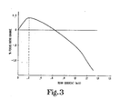
- FIGURE 3 is a graph illustrating a relationship inherent in the operation of the transformer shown in FIGURE 1.
- Referring to FIGURE 1, there is shown a portion of a video display apparatus including a cathode ray tube or picture tube 10 and a high voltage transformer 11.
- Signals illustratively received via
antenna 8 are applied tovideo processing circuitry 9, which demodulates and decodes the signal in an appropriate manner for application tovideo drive circuit 13. The output ofvideo drive circuit 13 is applied to picture tube 10, which incorporates anelectron gun assembly 12.Electron gun assembly 12, when energized, may illustratively produce three electron beams. Various operating voltage levels may be applied toelectron gun assembly 12, including a focus voltage level via aterminal 14. The electron beams are deflected to form a scanned raster bydeflection yoke 15. - A source of
AC voltage 16 is coupled to a rectifyingcircuit 17 which produces an unregulated DC voltage level that is applied to aregulator circuit 20, which may illustratively be of various types, such as switched-mode or SCR regulators. The output ofregulator 20 is a regulated DC voltage that is applied to one terminal of aprimary winding 21 of high voltage transformer 11. The other terminal ofprimary winding 21 is coupled to ahorizontal deflection circuit 22 which generates horizontal deflection signals that are applied to the horizontal deflection windings ofdeflection yoke 15 viaterminal 23. - High voltage transformer 11 includes a high voltage winding 24, comprising
winding segments diodes Winding 24 is energized byprimary winding 21 during the horizontal retrace interval and produces a high voltage level that is applied to the anode terminal of picture tube 10 viaconductor 25.Resistor 26 limits the current that can be provided by high voltage winding 24 in order to protect various electrical components of the video display apparatus. Atap 27 onhigh voltage winding 24 provides a focus voltage that is applied toelectron gun assembly 12 viaterminal 14.Tap 27 is selected so that the focus voltage is nominally of the order of one-third the high voltage level. The focus voltage generating portion of high voltage winding 24 will therefore comprise one-third of the full traverse of high voltage winding 24; i.e., one-third of the total number of winding turns ofhigh voltage winding 24. The focus voltage is supplied fromtap 27 toterminal 14 via anadjustable resistor 30. - High voltage transformer 11 also includes a load circuit supply winding 31 which, via appropriate rectifying diodes and filtering capacitors, produces a voltage level +V1 at a
terminal 32. Voltage level +V1 may illustratively be of the order of +230 volts and may be applied tovideo drive circuit 13. - As the electron beam current is increased due to viewer adjustment of the brightness control or due to changes in the picture scene brightness, the focus ratio, that is, the ratio of the focus voltage level to the high voltage level, may no longer provide the same quality of beam focus or sharpness as that provided at lower beam current levels. The RCA COTY-29 picture tube, for example, experiences improved beam focus at higher beam current levels as a result of a decreasing focus ratio as beam current increases beyond, for example, 0.2 milliamperes. In a typical circuit application, however, the focus ratio will remain constant or tend to increase at higher beam current levels, due to picture tube loading of the high voltage supply circuit.
- FIGURE 2 illustrates an embodiment of a high voltage transformer 11 in which supply winding 31 is wound in a manner that produces the previously described desirable decreasing focus ratio at high increasing beam current levels. Transformer 11 comprises a primary winding
bobbin 33 on which is wound the transformer primary winding 21.Primary winding 21 comprises upper and lower terminals that are connected toterminal stakes tertiary winding bobbin 34 surrounds the primary windingbobbin 33, and has high voltage winding 24 wound thereon. Thelower terminal 35 ofhigh voltage winding 24 is connected via aconductor 36 to aterminal stake 37. The focus-take offtap 27 is connected toterminal stake 40 via a conductor 41. In order to provide a nominal focus ratio of one-third,tap 27 is located at a distance equal to one-third of the total traverse of high voltage winding 24 fromlower terminal 35, thereby forming a focus voltage generatingwinding segment 42 as part ofhigh voltage winding 24. The upper terminal 43 ofhigh voltage winding 24 is connected to the cathode ray tubeanode terminal conductor 25 via aconductor 44. - In accordance with an aspect of the present invention, supply winding 31, which provides power to the
video drive circuit 13, is wound onbobbin 33 and overlaysprimary winding 21. Supply winding 31 is wound to cover or overlay only the upper one-half of the traverse ofprimary winding 21 and does not overlap the focusvoltage generating segment 42 of high voltage winding 24. Supply winding 31 will then be magnetically more tightly coupled to the upper portion of the traverse of high voltage winding 24 and magnetically less tightly coupled to the lower portion of the traverse of high voltage winding 24, which includes the focus voltage generatingwinding segment 42. Thelower terminal 45 andupper terminal 46 of supply winding 31 are illustratively connected toterminal stakes transformer housing 51.Housing 51 is filled with anepoxy compound 52 which pots the windings in a conventional manner. A magnetically permeable core 53 comprising upper andlower core segments primary bobbin 33. Acrushable spacing material 56 separatescore segments primary winding 21. -
Supply winding 31 provides power tovideo drive circuit 13 in order to drive theelectron gun assembly 12 of cathode ray tube 10 and is consequently heavily loaded; therefore an increase in electron beam current causes an increase in loading of supply winding 31. As previously described, supply winding 31 is magnetically coupled tohigh voltage winding 24. This magnetic coupling causes the loading of supply winding 31 to result in a corresponding loading ofhigh voltage winding 24. Substantial loading ofhigh voltage winding 24 by supply winding 31 occurs, however, only in the region closely coupled to supply winding 31, i.e., that portion ofhigh voltage winding 24 not associated with the generation of focus voltage. The primary winding generated retrace pulse appearing across the portion of high voltage winding 24 that is tightly coupled to supply winding 31 becomes flatter and broader because of the loading caused by supply winding 31. Rectifyingdiodes 62 and 63, associated with the loaded portion of winding 24, will conduct for a longer period of time than rectifyingdiode 61,therefore lowering the output impedance of the portion ofhigh voltage winding 24 tightly coupled to supply winding 31. The overall loading of winding 24 due to increasing beam current will therefore cause a greater decrease in focus voltage level relative to the decrease in high voltage level, due to the lowered output impedance of the high voltage generating portion ofhigh voltage winding 24. The focus ratio, i.e., the focus voltage level with respect to the high voltage level, will therefore decrease as the beam current increases. This results in improved electron beam focus characteristics with respect to beam current changes. The previously described winding arrangement of the primary winding with respect to the high voltage winding results in a constant degree of coupling between the primary and high voltage winding. The harmonic tuning of the transformer is not affected by changes in beam current or supply winding 31 loading. The arrangement of the present invention advantageously relies on the loading of the supply winding 31 to control the retrace pulse waveshape in a manner that results in desirable focus ratio changes in response to beam current variations. - FIGURE 3 graphically illustrates the percent change in focus ratio, with respect to a nominal ratio, associated with the use of the inventive transformer structure of FIGURE 2 as a result of beam current changes. At low beam current levels, less than 0.2 milliamperes, for example, an increase in beam current results in an increase in the focus ratio. This is due to the
resistor 30 loading the focus voltage generating portion of winding 24 and lowering the output impedance of the focus voltage generating circuit so that the high voltage level decreases relative to the focus voltage. For low beam current levels, this provides optimum focus characteristics. As the beam current increases, however, the previously described loading of the upper portion of high voltage winding predominates, resulting in a desirable decrease in focus ratio at high beam current levels. - The amount of the traverse of high voltage winding 24 that is overlaid by supply winding 31 may be selected to provide the desired change in focus ratio with respect to beam current in order to achieve optimum electron beam focus for a given cathode ray tube and video display apparatus.
Claims (8)
characterized in that a supply winding (31) energized by said primary winding (21) and located adjacent to said high voltage winding (24) for magnetic coupling thereto, occupies a region that has substantially no overlap with said focus potential generating segment.
Priority Applications (1)
| Application Number | Priority Date | Filing Date | Title |
|---|---|---|---|
| AT86303377T ATE68301T1 (en) | 1985-05-03 | 1986-05-02 | DEVICE FOR ADJUSTING THE FOCUS OF A CATHODE BEAM TUBE. |
Applications Claiming Priority (2)
| Application Number | Priority Date | Filing Date | Title |
|---|---|---|---|
| US73013185A | 1985-05-03 | 1985-05-03 | |
| US730131 | 1985-05-03 |
Publications (3)
| Publication Number | Publication Date |
|---|---|
| EP0200567A2 true EP0200567A2 (en) | 1986-11-05 |
| EP0200567A3 EP0200567A3 (en) | 1988-03-16 |
| EP0200567B1 EP0200567B1 (en) | 1991-10-09 |
Family
ID=24934050
Family Applications (1)
| Application Number | Title | Priority Date | Filing Date |
|---|---|---|---|
| EP86303377A Expired - Lifetime EP0200567B1 (en) | 1985-05-03 | 1986-05-02 | Crt focus tracking arrangement |
Country Status (12)
| Country | Link |
|---|---|
| US (1) | US4825129A (en) |
| EP (1) | EP0200567B1 (en) |
| JP (1) | JP2608050B2 (en) |
| KR (1) | KR950000288B1 (en) |
| AT (1) | ATE68301T1 (en) |
| AU (1) | AU590880B2 (en) |
| CA (1) | CA1262479A (en) |
| DE (1) | DE3681817D1 (en) |
| FI (1) | FI81935C (en) |
| HK (1) | HK189796A (en) |
| MX (1) | MX168060B (en) |
| SG (1) | SG138294G (en) |
Cited By (1)
| Publication number | Priority date | Publication date | Assignee | Title |
|---|---|---|---|---|
| DE3817892A1 (en) * | 1987-05-27 | 1988-12-08 | Rca Licensing Corp | Insulating high-voltage transformer for a video device |
Families Citing this family (5)
| Publication number | Priority date | Publication date | Assignee | Title |
|---|---|---|---|---|
| DE4127836A1 (en) * | 1991-08-22 | 1993-02-25 | Thomson Brandt Gmbh | High voltage diode-split transformer for TV receiver - ensures coupling of compartmented sec. to prim. winding surrounding auxiliary windings within two-part coaxial former |
| US6115085A (en) * | 1998-06-19 | 2000-09-05 | Thomson Licensing S.A. | Focus voltage tracking circuit |
| US5982641A (en) * | 1998-08-07 | 1999-11-09 | Thomson Consumer Electronics, Inc. | High-voltage power supply for video display apparatus |
| US6009006A (en) * | 1998-08-07 | 1999-12-28 | Thomson Consumer Electronics, Inc. | Synchronized high voltage generator |
| AU2003262401A1 (en) * | 2002-04-19 | 2003-11-03 | Thomson Licensing S.A. | Passive compensation of focus tracking utilizing winding and capacitor |
Citations (1)
| Publication number | Priority date | Publication date | Assignee | Title |
|---|---|---|---|---|
| EP0196857A2 (en) | 1985-03-29 | 1986-10-08 | RCA Thomson Licensing Corporation | Transformer winding arrangement especially for video display |
Family Cites Families (12)
| Publication number | Priority date | Publication date | Assignee | Title |
|---|---|---|---|---|
| BE791522A (en) * | 1971-11-18 | 1973-03-16 | Matsushita Electric Ind Co Ltd | HIGH VOLTAGE TRANSFORMER ASSOCIATED WITH A HORIZONTAL DIVIATION CIRCUIT |
| US3866086A (en) * | 1972-06-28 | 1975-02-11 | Matsushita Electric Ind Co Ltd | Flyback transformer apparatus |
| US3886434A (en) * | 1973-09-07 | 1975-05-27 | Warwick Electronics Inc | Flyback transformer |
| DE2514805C3 (en) * | 1975-04-04 | 1978-05-18 | Leybold-Heraeus Gmbh & Co Kg, 5000 Koeln | Arrangement for the power control of high-voltage electron beam generators |
| JPS5285416A (en) * | 1976-01-09 | 1977-07-15 | Hitachi Ltd | High-tension generating unit |
| US4183002A (en) * | 1978-05-26 | 1980-01-08 | Rca Corporation | Winding structure |
| JPS596488B2 (en) * | 1978-12-15 | 1984-02-13 | 三洋電機株式会社 | flyback transformer |
| US4334206A (en) * | 1979-08-23 | 1982-06-08 | Sanyo Electric Co., Ltd. | Ferrite core type transformer |
| JPS5638957U (en) * | 1979-09-03 | 1981-04-11 | ||
| DE3122589A1 (en) * | 1981-06-06 | 1983-01-05 | Standard Elektrik Lorenz Ag, 7000 Stuttgart | LINE TRANSFORMER FOR TELEVISIONS |
| JPS59108454A (en) * | 1982-12-14 | 1984-06-22 | Hitachi Ltd | Focus circuit of television receiver |
| US4587465A (en) * | 1984-11-30 | 1986-05-06 | Rca Corporation | Dynamic focus circuit |
-
1986
- 1986-04-25 FI FI861758A patent/FI81935C/en not_active IP Right Cessation
- 1986-04-28 AU AU56763/86A patent/AU590880B2/en not_active Ceased
- 1986-05-01 CA CA000508066A patent/CA1262479A/en not_active Expired
- 1986-05-02 MX MX002380A patent/MX168060B/en unknown
- 1986-05-02 EP EP86303377A patent/EP0200567B1/en not_active Expired - Lifetime
- 1986-05-02 JP JP61102933A patent/JP2608050B2/en not_active Expired - Lifetime
- 1986-05-02 AT AT86303377T patent/ATE68301T1/en not_active IP Right Cessation
- 1986-05-02 KR KR1019860003467A patent/KR950000288B1/en not_active IP Right Cessation
- 1986-05-02 DE DE8686303377T patent/DE3681817D1/en not_active Expired - Fee Related
-
1987
- 1987-10-29 US US07/115,547 patent/US4825129A/en not_active Expired - Lifetime
-
1994
- 1994-09-27 SG SG138294A patent/SG138294G/en unknown
-
1996
- 1996-10-10 HK HK189796A patent/HK189796A/en not_active IP Right Cessation
Patent Citations (1)
| Publication number | Priority date | Publication date | Assignee | Title |
|---|---|---|---|---|
| EP0196857A2 (en) | 1985-03-29 | 1986-10-08 | RCA Thomson Licensing Corporation | Transformer winding arrangement especially for video display |
Cited By (2)
| Publication number | Priority date | Publication date | Assignee | Title |
|---|---|---|---|---|
| DE3817892A1 (en) * | 1987-05-27 | 1988-12-08 | Rca Licensing Corp | Insulating high-voltage transformer for a video device |
| DE3817892C2 (en) * | 1987-05-27 | 1998-01-29 | Rca Licensing Corp | High voltage transformer |
Also Published As
| Publication number | Publication date |
|---|---|
| AU590880B2 (en) | 1989-11-23 |
| KR950000288B1 (en) | 1995-01-12 |
| US4825129A (en) | 1989-04-25 |
| FI861758A (en) | 1986-11-04 |
| FI81935C (en) | 1990-12-10 |
| JPS61256610A (en) | 1986-11-14 |
| FI861758A0 (en) | 1986-04-25 |
| EP0200567A3 (en) | 1988-03-16 |
| MX168060B (en) | 1993-05-03 |
| ATE68301T1 (en) | 1991-10-15 |
| AU5676386A (en) | 1986-11-06 |
| SG138294G (en) | 1995-01-13 |
| HK189796A (en) | 1996-10-18 |
| JP2608050B2 (en) | 1997-05-07 |
| EP0200567B1 (en) | 1991-10-09 |
| DE3681817D1 (en) | 1991-11-14 |
| CA1262479A (en) | 1989-10-24 |
| KR860009573A (en) | 1986-12-23 |
| FI81935B (en) | 1990-08-31 |
Similar Documents
| Publication | Publication Date | Title |
|---|---|---|
| US4257024A (en) | Color picture tube apparatus | |
| US4967121A (en) | Isolating high voltage transformer for video apparatus | |
| EP0200567B1 (en) | Crt focus tracking arrangement | |
| US5118999A (en) | Focus coil current generator for a cathode ray tube | |
| US5350980A (en) | Nonlinear inductor with magnetic field reduction | |
| US3914650A (en) | Television display apparatus provided with a circuit arrangement for generating a sawtooth current through a line deflection coil | |
| US3732458A (en) | Circuit arrangement for correcting the deflection of at least one electron beam in a television picture tube by means of a transductor | |
| US3609447A (en) | High voltage regulation circuit for a color television receiver | |
| EP0183514A2 (en) | Dynamic focus circuit | |
| CA1269694A (en) | Deflection distortion correction device | |
| US3798497A (en) | Solid-state television receiver with magnetically regulated power supply | |
| US3737572A (en) | Series-connected power supply and deflection circuits utilizing a single shunt regulator | |
| JPH05244448A (en) | Dynamic convergence circuit | |
| US4654564A (en) | Saturable reactor with toroidal shunt paths | |
| EP0013598B1 (en) | Combined linearity and side pincushion correction arrangement | |
| US4823100A (en) | Deflection distortion correction device | |
| CA2039784C (en) | Power supply for an electrode of a crt | |
| US7235935B2 (en) | Passive compensation of focus tracking utilizing winding and capacitor | |
| CA1292561C (en) | Isolating high voltage transformers for video apparatus | |
| US3980821A (en) | Power supply for a television receiver | |
| JPH06103934A (en) | Display device | |
| KR820000746B1 (en) | A circuit for correcting setup error in a color television receiver | |
| JPH0676761A (en) | Deflection yoke | |
| GB2322270A (en) | Circuit for eliminating radiated electric field noise in a video display | |
| KR20000046688A (en) | Apparatus for compensating mis-convergence of cathode ray tube |
Legal Events
| Date | Code | Title | Description |
|---|---|---|---|
| PUAI | Public reference made under article 153(3) epc to a published international application that has entered the european phase |
Free format text: ORIGINAL CODE: 0009012 |
|
| AK | Designated contracting states |
Kind code of ref document: A2 Designated state(s): AT DE FR GB |
|
| PUAL | Search report despatched |
Free format text: ORIGINAL CODE: 0009013 |
|
| AK | Designated contracting states |
Kind code of ref document: A3 Designated state(s): AT DE FR GB |
|
| RAP1 | Party data changed (applicant data changed or rights of an application transferred) |
Owner name: RCA LICENSING CORPORATION |
|
| 17P | Request for examination filed |
Effective date: 19880826 |
|
| 17Q | First examination report despatched |
Effective date: 19900702 |
|
| GRAA | (expected) grant |
Free format text: ORIGINAL CODE: 0009210 |
|
| AK | Designated contracting states |
Kind code of ref document: B1 Designated state(s): AT DE FR GB |
|
| REF | Corresponds to: |
Ref document number: 68301 Country of ref document: AT Date of ref document: 19911015 Kind code of ref document: T |
|
| REF | Corresponds to: |
Ref document number: 3681817 Country of ref document: DE Date of ref document: 19911114 |
|
| ET | Fr: translation filed | ||
| PLBE | No opposition filed within time limit |
Free format text: ORIGINAL CODE: 0009261 |
|
| STAA | Information on the status of an ep patent application or granted ep patent |
Free format text: STATUS: NO OPPOSITION FILED WITHIN TIME LIMIT |
|
| 26N | No opposition filed | ||
| PGFP | Annual fee paid to national office [announced via postgrant information from national office to epo] |
Ref country code: FR Payment date: 19930401 Year of fee payment: 8 |
|
| PGFP | Annual fee paid to national office [announced via postgrant information from national office to epo] |
Ref country code: AT Payment date: 19930421 Year of fee payment: 8 |
|
| PG25 | Lapsed in a contracting state [announced via postgrant information from national office to epo] |
Ref country code: AT Effective date: 19940502 |
|
| PG25 | Lapsed in a contracting state [announced via postgrant information from national office to epo] |
Ref country code: FR Effective date: 19950131 |
|
| REG | Reference to a national code |
Ref country code: FR Ref legal event code: ST |
|
| REG | Reference to a national code |
Ref country code: GB Ref legal event code: 732E |
|
| PGFP | Annual fee paid to national office [announced via postgrant information from national office to epo] |
Ref country code: GB Payment date: 20010319 Year of fee payment: 16 |
|
| PGFP | Annual fee paid to national office [announced via postgrant information from national office to epo] |
Ref country code: DE Payment date: 20010320 Year of fee payment: 16 |
|
| REG | Reference to a national code |
Ref country code: GB Ref legal event code: IF02 |
|
| PG25 | Lapsed in a contracting state [announced via postgrant information from national office to epo] |
Ref country code: GB Free format text: LAPSE BECAUSE OF NON-PAYMENT OF DUE FEES Effective date: 20020502 |
|
| PG25 | Lapsed in a contracting state [announced via postgrant information from national office to epo] |
Ref country code: DE Free format text: LAPSE BECAUSE OF NON-PAYMENT OF DUE FEES Effective date: 20021203 |
|
| GBPC | Gb: european patent ceased through non-payment of renewal fee |
Effective date: 20020502 |