EP0200553A2 - Optical dust detector assembly - Google Patents
Optical dust detector assembly Download PDFInfo
- Publication number
- EP0200553A2 EP0200553A2 EP86303322A EP86303322A EP0200553A2 EP 0200553 A2 EP0200553 A2 EP 0200553A2 EP 86303322 A EP86303322 A EP 86303322A EP 86303322 A EP86303322 A EP 86303322A EP 0200553 A2 EP0200553 A2 EP 0200553A2
- Authority
- EP
- European Patent Office
- Prior art keywords
- duct member
- air
- flow
- detector assembly
- dust
- Prior art date
- Legal status (The legal status is an assumption and is not a legal conclusion. Google has not performed a legal analysis and makes no representation as to the accuracy of the status listed.)
- Granted
Links
- 239000000428 dust Substances 0.000 title claims abstract description 69
- 230000003287 optical effect Effects 0.000 title claims abstract description 31
- 230000002093 peripheral effect Effects 0.000 claims abstract description 14
- 238000001514 detection method Methods 0.000 claims description 13
- 230000004044 response Effects 0.000 claims description 7
- 239000000779 smoke Substances 0.000 claims description 2
- 239000002245 particle Substances 0.000 description 23
- XLYOFNOQVPJJNP-UHFFFAOYSA-N water Substances O XLYOFNOQVPJJNP-UHFFFAOYSA-N 0.000 description 8
- 230000004048 modification Effects 0.000 description 5
- 238000012986 modification Methods 0.000 description 5
- 238000005192 partition Methods 0.000 description 5
- 230000007423 decrease Effects 0.000 description 4
- 230000005540 biological transmission Effects 0.000 description 2
- 238000010586 diagram Methods 0.000 description 2
- 230000000694 effects Effects 0.000 description 2
- 238000000926 separation method Methods 0.000 description 2
- 238000000149 argon plasma sintering Methods 0.000 description 1
- 230000000903 blocking effect Effects 0.000 description 1
- 230000008859 change Effects 0.000 description 1
- 238000010276 construction Methods 0.000 description 1
- 238000011109 contamination Methods 0.000 description 1
- 230000001419 dependent effect Effects 0.000 description 1
- 238000002474 experimental method Methods 0.000 description 1
- 230000002265 prevention Effects 0.000 description 1
Images


Classifications
-
- G—PHYSICS
- G01—MEASURING; TESTING
- G01N—INVESTIGATING OR ANALYSING MATERIALS BY DETERMINING THEIR CHEMICAL OR PHYSICAL PROPERTIES
- G01N21/00—Investigating or analysing materials by the use of optical means, i.e. using sub-millimetre waves, infrared, visible or ultraviolet light
- G01N21/17—Systems in which incident light is modified in accordance with the properties of the material investigated
- G01N21/47—Scattering, i.e. diffuse reflection
- G01N21/49—Scattering, i.e. diffuse reflection within a body or fluid
- G01N21/53—Scattering, i.e. diffuse reflection within a body or fluid within a flowing fluid, e.g. smoke
- G01N21/534—Scattering, i.e. diffuse reflection within a body or fluid within a flowing fluid, e.g. smoke by measuring transmission alone, i.e. determining opacity
-
- F—MECHANICAL ENGINEERING; LIGHTING; HEATING; WEAPONS; BLASTING
- F02—COMBUSTION ENGINES; HOT-GAS OR COMBUSTION-PRODUCT ENGINE PLANTS
- F02B—INTERNAL-COMBUSTION PISTON ENGINES; COMBUSTION ENGINES IN GENERAL
- F02B3/00—Engines characterised by air compression and subsequent fuel addition
- F02B3/06—Engines characterised by air compression and subsequent fuel addition with compression ignition
-
- G—PHYSICS
- G01—MEASURING; TESTING
- G01N—INVESTIGATING OR ANALYSING MATERIALS BY DETERMINING THEIR CHEMICAL OR PHYSICAL PROPERTIES
- G01N1/00—Sampling; Preparing specimens for investigation
- G01N1/02—Devices for withdrawing samples
- G01N1/22—Devices for withdrawing samples in the gaseous state
Definitions
- the present invention relates to an optical , but not necessarily exclusively, detector assembly and more particularly/to an optical dust detector assembly adapted for use in an automotive vehicle for detecting the concentration of dust, smoke or the like contained in a flow of air passing therethrough.
- An optical dust detector assembly of this type has been proposed which /includes a cylindrical air duct member having an introductory portion with an inlet opening, and a base portion with an outlet opening, for permitting dust-containing air to pass therethrough, the air duct member having a pair of radial holes formed in its peripheral wall and opposed to each other, a pair of casings .-at the peripheral wall of the air duct member on both sides thereof with respective opening ends communicating with the interior of the air duct member through the respective radial holes thereof, a light emission element arranged within one of the casings to emit a light beam therefrom and pass it through the radial holes toward the other casing, and a light receiving element arranged within the other casing to receive the light beam emitted from the light emission element and passed through the radial holes, the light receiving element detecting a decrease in the intensity of the received light beam caused in response to an increase of the dust concentration in the air introduced into the air duct member through the introductory portion thereof.
- an object of the present invention to provide an improved optical detector assembly wherein, in view of the fact that dust particles are much smaller in both diameter and mass than the foreign particles such as dirt, rain, snow, sleet or at least some of water splash, / the latter are separated from the flow of dust-containing air passing through the air duct member so as to prevent,adhesion of the foreign particles to the optical elements of the detector assembly, and to enable reliable detection of the dust concentration in the flow of air.
- the object is accomplished by the provision of an optical dust detector assembly of the kind described hereinbefore, wherein to provide the air duct member is;adapted or can be arranged in such a manner as/ therein an inclined internal surface for deflecting the flow of air introduced through the introductory portion thereof, and wherein the radial holes are formed in a peripheral wall of the base portion of the duct member to face the flow of air deflected by the inclined internal surface.
- the optical dust detector assembly is arranged in a fore-and-aft direction on a vehicle body structure
- the introductory portion of the duct member is bent in such a manner as to incline downwardly from the base portion toward the front of the vehicle so as to form an inclined internal surface for deflecting upwardly the flow of air introduced therein, wherein the radial holes are formed in a peripheral wall of the base portion of the duct member to face the air flow deflected upwardly by the inclined internal surface.
- the base, portion of the duct member may be bent in such a manner as to incline upwardly from the introductory portion toward the rear of the vehicle so as to form an inclined internal surface for deflecting upwardly the flow of air introduced therein through the introductory portion, wherein the radial holes are formed in a peripheral wall of the base portion of the duct member to face the flow of air deflected upwardly by the inclined internal surface.
- an electric control apparatus coupled to the dust detector assembly comprises a standard signal generator for producing a standard signal indicative of a predetermined concentration of dust, a comparator responsive to an output signal from the light receiving element and the standard signal from the standard signal generator to produce a high level signal therefrom when the output signal is maintained at a lower level than the standard signal level, a discrimination circuit responsive to the high level signal from the comparator to produce a detection signal therefrom only when the high level signal is maintained for a period of time more than a predetermined duration, and an output signal generator arranged to produce a control signal therefrom in response to the detection signal from the discrimination circuit.
- Figs. 1 through 3 show an optical dust detector assembly S of the light transmission type in accordance with the present invention, which is coupled to an electric control apparatus for an automobile air conditioner.
- the optical dust detector assembly S is fixedly mounted on the central portion of a lateral plate 13 the opposite ends of which are fixed to a pair of parallel chassis arms 12, 12 extending between a radiator 10 in front of a vehicle engine (not shown) and a front bumper 11 of the vehicle.
- the optical dust detector assembly S includes a cylindrical air duct member 20, a pair of cylindrical casings 30, 40, a light emission element 50, and a light receiving element 60.
- the air duct member 20 includes an introductory portion 21 and a base portion 22 and is fixedly mounted on the lateral plate 13 in a fore-and-aft direction of the vehicle.
- the introductory portion 21 has an inlet opening directed toward front bumper 11, being bent to incline downwardly from the base portion 22 toward the front of the vehicle.
- the base portion 22 is arranged parallel to the surface of lateral plate 13 and has a pair of radial holes 22a and 22b formed in its peripheral wall and opposed to each other.
- the casing 30 is arranged in such a manner that the central axis thereof is perpendicular to the central axis of base portion 22 and has an opening end 31 fixed to the periphery of radial hole 22a.
- the casing 40 is arranged symmetrically to the casing 30 with respect to base portion 22 and has an opening end 41 fixed to the periphery of radial hole 22b.
- the central axes of both casings 30 and 40 coincide with each other.
- the light emission element 50 is in the form of a light emitting diode which is fixedly mounted in place within the bottom portion of casing 30 with a light emission surface 51 thereof directed toward opening end 31 in such a manner that the axis of the light beam emitted from the light emission element 50 coincides with the central axis of casing 30.
- a pair of laterally spaced partition plates 32 and 33 which are formed at their central portions with central holes 32a and 33a respectively, the centers of which central holes 32a and 33a are aligned with the axis of the emitted light beam and the inner diameters of which are smaller than that of radial hole 22a of base portion 22.
- the light beam emitted from light emission element 50 passes through the light emission surface 51 and the central holes 32a and 33a.
- the light receiving element 60 is in the form of a photo transistor which is fixedly mounted in place within the bottom portion of casing 40 with a light receiving surface 61 thereof directed toward opening end 41 in such a manner that the axis of the light beam received by light receiving element 60 coincides with the central axis of casing 40.
- a pair of laterally spaced partition plates 42 and 43 which are formed at their central portions with central holes 42a and 43a respectively, the centers of which central holes 42a and 43a are aligned with the axis of the light beam to be received, and the inner diameters of which are smaller than that of radial hole 22b of base portion 22.
- the light receiving element 60 produces an electric output signal indicative of the intensity of the light beam which is emitted from light emission element 50, passes across the interior of base portion 22 of air duct member 20, and is received by light receiving surface 61.
- the light beam emitted from light emission element 50 passes through central holes 32a, 33a in partition plates 32, 33, radial holes 22a, 22b in the peripheral wall of base portion 22, and central holes 42a, 43a in partition plates 42, 43.
- the light beam travels along the light emission axis and then along the light receiving axis and is received by the light receiving element 60, which produces an electric output signal indicative of the intensity of the ligh beam.
- Foreign particles such as dirt, rain, snow, sleet, or water splash, which are carried by the air flow and enter into the air duct member 20 with the dust, flow straight on and are separated from the upwardly bent air flow due to their large size or large inertia in comparison with the dust. They collide with the lower inside surface of introductory portion 21 and fall therealong, thereby to be reliably prevented from entering into base portion 22.
- dust-containing air free from foreign particles flows into the base portion 22.
- the intensity of the light beam received by light receiving element 60 is not affected by the presence of the foreign particles, so that the light receiving element can produce accurately an electric output signal indicative of the dust concentration only in the air flow.
- reliable prevention of the foreign particles from entering into base portion 22 serves for effective protection of both light emission element 50 and light receiving element 60 from contamination by the foreign particles.
- an air duct member 20 whose dimensions and angles are determined as follows is capable of effecting reliable dust separation from foreign particles in order to obtain satisfactory experimental results when the speed of the vehicle is varied between 0 to 110Km/h, corresponding to a speed of the air flow at the optical dust detector assembly S between 0 - 60Km/h:
- a cylindrical air duct member 70 is employed in place of the air duct member 20 in the above-described embodiment.
- the air duct member 70 has an introductory portion 71 directed toward the front bumper 11, and a base portion 72, and is fixedly mounted on the lateral plate 13 .
- the introductory portion 71 is arranged in parallel to the surface of lateral plate 13 and has an inlet opening 71a widened toward the front of the vehicle.
- the base portion 72 is bent in such a manner as to incline upwardly from the introductory portion 21 toward the rear of the vehicle and has a pair of radial holes 72a, 72b formed in its peripheral wall and opposed to each other.
- radial holes 72a, 72b Fixed to the peripheries of radial holes 72a, 72b are a pair of casings 30, 40 with opening ends 31, 41 respectively to communicate with the interior of air duct member 70.
- a series of dimensions and angles applied to the air duct member 70, being F - H and ⁇ d - 8f as designated in Fig. 5, are to be determined by taking the criteria as described in the previous embodiment into consideration.
- the remaining construction is substantially the same as that of the first-described embodiment.
- FIG. 6 there is schematically illustrated a block diagram of an electric control apparatus coupled to the optical dust detector assembly shown in Figs. 1 and
- the electric control apparatus includes a driving circuit 70 connected to the light emitting diode 50, an amplifier 80 connected to the photo transistor 60, a standard signal generator 90, a comparison circuit 100 connected to the amplifier 80 and standard signal generator 90, a discrimination circuit 110 connected to the comparison circuit 100, and an output signal generator 120.
- the driving circuit 70 is connected to an electric power source in the form of a vehicle battery (not shown) through a user actuable switch to energize the light emitting diode 50 in its activated condition.
- the amplifier 80 is arranged to amplify an electric output signal indicative of the dust concentration applied thereto from the photo transistor 60 so as to produce an amplified signal therefrom.
- the standard signal generator 90 is arranged to produce a standard signal indicative of a predetermined concentration of the dust, dirt, rain, snow, sleet, water splash and the like contained in a flow of air introduced into the air duct member 20 of the detector assembly S.
- the comparison circuit 100 is responsive to the amplified signal from amplifier 80 and the standard signal from generator 90 to produce a high level signal therefrom when the amplified signal is maintained at a lower level than the standard signal level.
- the discrimination circuit 110 is responsive to the high level signal from comparison circuit 100 to produce a detection signal therefrom only when the high level signal is maintained for a period of time more than a predetermined duration.
- the output signal generator 120 is arranged to produce a control signal in response to the detection signal from discrimination circuit 110.
- said predetermined duration for discrimination of the high level signal from comparison circuit 100 is determined to be 3ms - 30ms for the following reason.
- the level of an electric output signal of photo transistor 60 decreases in dependence upon an increase of the concentration of dust contained in a flow of air passing through the air duct member 20 of the dust detector assembly S.
- the output signal of photo transistor 60 is amplified by the amplifier 90 and applied to the comparison circuit 100. While the level of the amplified signal is maintained below the level of the standard signal from standard signal generator 90, the comparison circuit 100 produces a high level signal indicative of the concentration of dust.
- the discrimination circuit 110 produces a detection signal therefrom in response to the high level signal of dust in the air flow.
- the output from comparison circuit 100 only in response to the amount/ signal generator 120 produces a control signal therefrom in response to the detection signal from discrimination circuit 110. This enables reliable detection of the dust concentration in the flow of air passing through the air duct member 20 of the detector assembly S.
- the comparison circuit 100 When any dust is not contained in the flow of air, the comparison circuit 100 does not produce any high level signal therefrom because the level of the amplified signal from amplifier 80 is maintained above the standard signal level. If the level of the amplified signal from amplifier 80 drops below the standard signal level due to presence of foreign particles in the base portion 22 of air duct member 20, the high level signal of comparison circuit 100 will disappear within the predetermined duration of 3ms - 30ms. In such a situation, the discrimination circuit 110 does not produce any detection signal therefrom, to avoid errors in detection of the dust concentration in the flow of air. ;
- the present invention is applied to an optical dust detector assembly of the light transmission type, but is applicable also to a detector assembly of the light scattering type.
- the introductory and base portions 21 and 22 may form a continuous tube without any bend in it, and may be so arranged on the vehicle as to be inclined upwardly from the inlet to the outlet to provide the same separating effect as in the previously described and illustrated embodiments.
Abstract
Description
- The present invention relates to an optical , but not necessarily exclusively, detector assembly and more particularly/to an optical dust detector assembly adapted for use in an automotive vehicle for detecting the concentration of dust, smoke or the like contained in a flow of air passing therethrough.
- An optical dust detector assembly of this type has been proposed which /includes a cylindrical air duct member having an introductory portion with an inlet opening, and a base portion with an outlet opening, for permitting dust-containing air to pass therethrough, the air duct member having a pair of radial holes formed in its peripheral wall and opposed to each other, a pair of casings .-at the peripheral wall of the air duct member on both sides thereof with respective opening ends communicating with the interior of the air duct member through the respective radial holes thereof, a light emission element arranged within one of the casings to emit a light beam therefrom and pass it through the radial holes toward the other casing, and a light receiving element arranged within the other casing to receive the light beam emitted from the light emission element and passed through the radial holes, the light receiving element detecting a decrease in the intensity of the received light beam caused in response to an increase of the dust concentration in the air introduced into the air duct member through the introductory portion thereof.
- In such a proposed optical dust detector assembly as described, depending on the position of the detector assembly in the vehicle, small foreign particles such as dirt, rain, snow, sleet or water splash may be present in the dust-containing air introduced through the introductory portion of the air duct member. This causes the intensity of the received light beam to be varied due to the presence of those foreign particles other than dust. In other words, the optical dust detector assembly will detect not only dust to be detected but also those foreign particles other than the dust, resulting in the occurrence of errors in dust detection. Furthermore, by adhesion of the foreign particles to the light emission element, light receiving element or other optical elements, the optical functions of the dust detector assembly may deteriorate.
- It is, therefore, an object of the present invention to provide an improved optical detector assembly wherein, in view of the fact that dust particles are much smaller in both diameter and mass than the foreign particles such as dirt, rain, snow, sleet or at least some of water splash,/the latter are separated from the flow of dust-containing air passing through the air duct member so as to prevent,adhesion of the foreign particles to the optical elements of the detector assembly, and to enable reliable detection of the dust concentration in the flow of air.
- According to the present invention, the object is accomplished by the provision of an optical dust detector assembly of the kind described hereinbefore, wherein to provide the air duct member is;adapted or can be arranged in such a manner as/ therein an inclined internal surface for deflecting the flow of air introduced through the introductory portion thereof, and wherein the radial holes are formed in a peripheral wall of the base portion of the duct member to face the flow of air deflected by the inclined internal surface. In the case that the optical dust detector assembly is arranged in a fore-and-aft direction on a vehicle body structure, it is preferable that the introductory portion of the duct member is bent in such a manner as to incline downwardly from the base portion toward the front of the vehicle so as to form an inclined internal surface for deflecting upwardly the flow of air introduced therein, wherein the radial holes are formed in a peripheral wall of the base portion of the duct member to face the air flow deflected upwardly by the inclined internal surface. Alternatively, the base, portion of the duct member may be bent in such a manner as to incline upwardly from the introductory portion toward the rear of the vehicle so as to form an inclined internal surface for deflecting upwardly the flow of air introduced therein through the introductory portion, wherein the radial holes are formed in a peripheral wall of the base portion of the duct member to face the flow of air deflected upwardly by the inclined internal surface.
- In a practical embodiment of the present invention, an electric control apparatus coupled to the dust detector assembly comprises a standard signal generator for producing a standard signal indicative of a predetermined concentration of dust, a comparator responsive to an output signal from the light receiving element and the standard signal from the standard signal generator to produce a high level signal therefrom when the output signal is maintained at a lower level than the standard signal level, a discrimination circuit responsive to the high level signal from the comparator to produce a detection signal therefrom only when the high level signal is maintained for a period of time more than a predetermined duration, and an output signal generator arranged to produce a control signal therefrom in response to the detection signal from the discrimination circuit.
- Features and advantages of embodiments of the present invention will become more readily apparent from the following detailed description of preferred embodiments thereof when taken together with the accompanying drawings, in which;
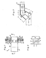
- Fig. 1 is a fragmentary cross-sectional plan view of an optical dust detector assembly in accordance with the present invention;
- Fig. 2 illustrates an arrangement of the detector assembly of Fig. 1 on a vehicle body structure;
- Fig. 3 is a cross-sectional side view taken along line III-III in Fig. 1;
- Fig. 4 is a fragmentary cross-sectional plan view of a modification of the assembly of Figs.1 and 3;
- Fig. 5 is a cross-sectional side view taken along line V-V in Fig. 4;
- Fig. 6 illustrates a block diagram of an electric control apparatus coupled to the optical dust detector assembly shown in Figs. 1 and 3; and
- Fig. 7 is a graph illustrating the 'duration of high level signals indicative of the concentration of rain, snow, sleet, water splash and dust.
- With reference to the drawings, Figs. 1 through 3 show an optical dust detector assembly S of the light transmission type in accordance with the present invention, which is coupled to an electric control apparatus for an automobile air conditioner. As is illustrated in Fig. 2, the optical dust detector assembly S is fixedly mounted on the central portion of a
lateral plate 13 the opposite ends of which are fixed to a pair ofparallel chassis arms radiator 10 in front of a vehicle engine (not shown) and afront bumper 11 of the vehicle. As is illustrated in Figs. 1 and 3, the optical dust detector assembly S includes a cylindricalair duct member 20, a pair ofcylindrical casings light emission element 50, and alight receiving element 60. - The
air duct member 20 includes anintroductory portion 21 and abase portion 22 and is fixedly mounted on thelateral plate 13 in a fore-and-aft direction of the vehicle. Theintroductory portion 21 has an inlet opening directed towardfront bumper 11, being bent to incline downwardly from thebase portion 22 toward the front of the vehicle. Thebase portion 22 is arranged parallel to the surface oflateral plate 13 and has a pair ofradial holes casing 30 is arranged in such a manner that the central axis thereof is perpendicular to the central axis ofbase portion 22 and has anopening end 31 fixed to the periphery ofradial hole 22a. Thecasing 40 is arranged symmetrically to thecasing 30 with respect tobase portion 22 and has anopening end 41 fixed to the periphery ofradial hole 22b. Here the central axes of bothcasings - The
light emission element 50 is in the form of a light emitting diode which is fixedly mounted in place within the bottom portion ofcasing 30 with alight emission surface 51 thereof directed towardopening end 31 in such a manner that the axis of the light beam emitted from thelight emission element 50 coincides with the central axis ofcasing 30. Provided within thecasing 30 betweenlight emission surface 51 and openingend 31 are a pair of laterally spacedpartition plates central holes central holes radial hole 22a ofbase portion 22. The light beam emitted fromlight emission element 50 passes through thelight emission surface 51 and thecentral holes - The
light receiving element 60 is in the form of a photo transistor which is fixedly mounted in place within the bottom portion ofcasing 40 with alight receiving surface 61 thereof directed towardopening end 41 in such a manner that the axis of the light beam received by lightreceiving element 60 coincides with the central axis ofcasing 40. Provided within thecasing 40 betweenlight receiving surface 61 and openingend 41 are a pair of laterally spacedpartition plates central holes central holes radial hole 22b ofbase portion 22. Thelight receiving element 60 produces an electric output signal indicative of the intensity of the light beam which is emitted fromlight emission element 50, passes across the interior ofbase portion 22 ofair duct member 20, and is received bylight receiving surface 61. - In the arrangement of the optical dust detector assembly as described above, a series of dimensions and angles applied to the
air duct member 20, being A - E and 6a - 8c as designated in Fig. 3, are to be determined by taking the following criteria into consideration: - 1. Since the size of dust particles, about 0.02-30Vm in diameter, is smaller than that of foreign particles other than dust, such as dirt, rain, snow, sleet or water splash which are about 0.15mm - 3mm in diameter, the mass of dust is much smaller than that of the foreign particles. As a result, when the vehicle is moving or stationary with the fan of
radiator 10 running, if the flow of air is deflected upwardly, from being parallel tolateral plate 13, by conducting it through the upwardly inclinedintroductory portion 21 ofair duct member 20, dust particles are readily drawn into the upward flow of air while foreign particles flow straight on due to their larger.inertia. This phenomenon is also influenced by the velocity range of the air flow. - 2. In the case that the height A of the inlet opening of
introductory portion 21, or the area of the inlet opening thereof, is properly determined, it is desirable to make the length B-of the upper side ofintroductory portion 21 possibly longer for more effective separation of the foreign particles. - In operation, when the optical dust detector assembly S as described above is activated, the light beam emitted from
light emission element 50 passes throughcentral holes partition plates radial holes base portion 22, andcentral holes partition plates receiving element 60, which produces an electric output signal indicative of the intensity of the ligh beam. When the vehicle is in motion, dust whose mass is as small as described above is readily carried along with the air flow from the inlet opening ofintroductory portion 21, through thebase portion 22 ofduct member 20 toward the rear of the vehicle in such a manner as to change its flow direction smoothly from horizontal to upwardly along the upwardly bentintroductory portion 21, and then back again to horizontal along thebase portion 22. As a result, the intensity of the light beam received bylight receiving element 60 decreases in dependence upon an increase of the dust concentration in the air flow, causing a decrease in the value of the electric output signal. In this case, even when the dust-containing air enters intocasings radial holes light emission element 50 andlight receiving element 60 is reliably protected from dust by the blocking action ofcentral holes partition plates - Foreign particles such as dirt, rain, snow, sleet, or water splash, which are carried by the air flow and enter into the
air duct member 20 with the dust, flow straight on and are separated from the upwardly bent air flow due to their large size or large inertia in comparison with the dust. They collide with the lower inside surface ofintroductory portion 21 and fall therealong, thereby to be reliably prevented from entering intobase portion 22. Thus, dust-containing air free from foreign particles flows into thebase portion 22. As a result, the intensity of the light beam received bylight receiving element 60 is not affected by the presence of the foreign particles, so that the light receiving element can produce accurately an electric output signal indicative of the dust concentration only in the air flow. Furthermore, reliable prevention of the foreign particles from entering intobase portion 22 serves for effective protection of bothlight emission element 50 andlight receiving element 60 from contamination by the foreign particles. - In a practical embodiment, an
air duct member 20 whose dimensions and angles are determined as follows is capable of effecting reliable dust separation from foreign particles in order to obtain satisfactory experimental results when the speed of the vehicle is varied between 0 to 110Km/h, corresponding to a speed of the air flow at the optical dust detector assembly S between 0 - 60Km/h: - θa = 40 - 50°, 8b = 45°, 8c = 55 , B = 40mm,
- C = 40mm, and D = 5mm.
- Describing now a modification of the optical dust detector assembly in accordance with the present invention, as shown in Figs. 4 and 5, a cylindrical
air duct member 70 is employed in place of theair duct member 20 in the above-described embodiment. Theair duct member 70 has anintroductory portion 71 directed toward thefront bumper 11, and abase portion 72, and is fixedly mounted on thelateral plate 13 . Theintroductory portion 71 is arranged in parallel to the surface oflateral plate 13 and has an inlet opening 71a widened toward the front of the vehicle. Thebase portion 72 is bent in such a manner as to incline upwardly from theintroductory portion 21 toward the rear of the vehicle and has a pair ofradial holes 72a, 72b formed in its peripheral wall and opposed to each other. Fixed to the peripheries ofradial holes 72a, 72b are a pair ofcasings opening ends air duct member 70. A series of dimensions and angles applied to theair duct member 70, being F - H and θd - 8f as designated in Fig. 5, are to be determined by taking the criteria as described in the previous embodiment into consideration. The remaining construction is substantially the same as that of the first-described embodiment. - In the operation of this modification, similarly to the first-described embodiment, foreign particles which are carried by the air flow and enter into the
air duct member 70 with the dust flow straight on. They are separated from the upwardly bent air flow at the rear end ofintroductory portion 71 by colliding with the lower inside surface ofbase portion 72 and thus are prevented from entering into bothradial holes 72a and 72b. As a result, the dust-containing air free from foreign particles flows throughbase portion 72 between radial holes 72a and 72b.to achieve the same effects as those of the first-described embodiment. In a practical embodiment of this modification, anair duct member 70 whose dimensions and angles are determined as follows is capable of obtaining substantially the same satisfactory experimental results as those of the first-described embodiment: - θd = 39° - 47°, θe = 27° -37°, θf = 51° - 56°,
- F = 13mm - 15mm, G = 7mm - 13mm, and H = 15mm
- In Fig. 6, there is schematically illustrated a block diagram of an electric control apparatus coupled to the optical dust detector assembly shown in Figs. 1 and
- 3. The electric control apparatus includes a driving
circuit 70 connected to thelight emitting diode 50, anamplifier 80 connected to thephoto transistor 60, astandard signal generator 90, acomparison circuit 100 connected to theamplifier 80 andstandard signal generator 90, adiscrimination circuit 110 connected to thecomparison circuit 100, and anoutput signal generator 120. The drivingcircuit 70 is connected to an electric power source in the form of a vehicle battery (not shown) through a user actuable switch to energize thelight emitting diode 50 in its activated condition. Theamplifier 80 is arranged to amplify an electric output signal indicative of the dust concentration applied thereto from thephoto transistor 60 so as to produce an amplified signal therefrom. Thestandard signal generator 90 is arranged to produce a standard signal indicative of a predetermined concentration of the dust, dirt, rain, snow, sleet, water splash and the like contained in a flow of air introduced into theair duct member 20 of the detector assembly S. Thecomparison circuit 100 is responsive to the amplified signal fromamplifier 80 and the standard signal fromgenerator 90 to produce a high level signal therefrom when the amplified signal is maintained at a lower level than the standard signal level. Thediscrimination circuit 110 is responsive to the high level signal fromcomparison circuit 100 to produce a detection signal therefrom only when the high level signal is maintained for a period of time more than a predetermined duration. Theoutput signal generator 120 is arranged to produce a control signal in response to the detection signal fromdiscrimination circuit 110. In this embodiment, said predetermined duration for discrimination of the high level signal fromcomparison circuit 100 is determined to be 3ms - 30ms for the following reason. - In an experiment, it has been observed that when the concentration of dust, rain, snow, sleet or water splash introduced into the
air duct member 20 exceeds the predetermined value defined by the standard signal, the high level signal fromcomparison circuit 100 is maintained as shown in Fig. 7. The reference characters P1 - P6 in Fig. 7 represent the facts that the high level signal indicative of the concentration of rain in a field is maintained for a period of 1.8ms, that the high level signal indicative of the concentration of rain in a wind tunnel is maintained for a period of 3ms, that the high level signal indicative of the concentration of snow is maintained:for a period of 0.2ms - 1.9ms, that the high level signal indicative of the concentration of sleet is maintained for a period of 0.2ms - 1.7ms, that the high level signal indicative of the concentration of water splash is maintained for a period of 0.3ms - 1.3ms, and that the high level signal indicative of the concentration of dust is maintained for a period of 30ms - 1700ms. - In operation of the electric control apparatus, the level of an electric output signal of
photo transistor 60 decreases in dependence upon an increase of the concentration of dust contained in a flow of air passing through theair duct member 20 of the dust detector assembly S. The output signal ofphoto transistor 60 is amplified by theamplifier 90 and applied to thecomparison circuit 100. While the level of the amplified signal is maintained below the level of the standard signal fromstandard signal generator 90, thecomparison circuit 100 produces a high level signal indicative of the concentration of dust. In such a condition, even if the high level signal ofcomparison circuit 100 is partly caused by presence of foreign particles in thebase portion 22 ofair duct member 20, only the dust-dependent signal which is will be maintained during a period of 30ms - 1700ms,/ more than the predetermined duration of 3ms - 30ms. Thus, thediscrimination circuit 110 produces a detection signal therefrom in response to the high level signal of dust in the air flow. The output fromcomparison circuit 100 only in response to the amount/signal generator 120 produces a control signal therefrom in response to the detection signal fromdiscrimination circuit 110. This enables reliable detection of the dust concentration in the flow of air passing through theair duct member 20 of the detector assembly S. - When any dust is not contained in the flow of air, the
comparison circuit 100 does not produce any high level signal therefrom because the level of the amplified signal fromamplifier 80 is maintained above the standard signal level. If the level of the amplified signal fromamplifier 80 drops below the standard signal level due to presence of foreign particles in thebase portion 22 ofair duct member 20, the high level signal ofcomparison circuit 100 will disappear within the predetermined duration of 3ms - 30ms. In such a situation, thediscrimination circuit 110 does not produce any detection signal therefrom, to avoid errors in detection of the dust concentration in the flow of air. ; - In the above-described embodiments, the present invention is applied to an optical dust detector assembly of the light transmission type, but is applicable also to a detector assembly of the light scattering type.
- Having now fully set forth both structure and operation of certain preferred embodiments of the concept underlying the present invention, various other embodiments as well as certain variations and modifications of the embodiments herein shown- and described will obviously occur to those skilled in the art upon becoming familiar with said underlying concept. It is to be understood, therefore, that within the scope of the appended claims, the invention may be practiced otherwise than as specifically set forth herein.
- For example, in some embodiments the introductory and
base portions
Claims (6)
Applications Claiming Priority (4)
| Application Number | Priority Date | Filing Date | Title |
|---|---|---|---|
| JP9476585A JPS61253445A (en) | 1985-05-01 | 1985-05-01 | Dust sensor for vehicle |
| JP94765/85 | 1985-05-01 | ||
| JP193324/85 | 1985-09-02 | ||
| JP60193324A JPS6252439A (en) | 1985-09-02 | 1985-09-02 | Optical detector for vehicle |
Publications (3)
| Publication Number | Publication Date |
|---|---|
| EP0200553A2 true EP0200553A2 (en) | 1986-11-05 |
| EP0200553A3 EP0200553A3 (en) | 1988-01-13 |
| EP0200553B1 EP0200553B1 (en) | 1990-12-19 |
Family
ID=26436001
Family Applications (1)
| Application Number | Title | Priority Date | Filing Date |
|---|---|---|---|
| EP86303322A Expired - Lifetime EP0200553B1 (en) | 1985-05-01 | 1986-05-01 | Optical dust detector assembly |
Country Status (3)
| Country | Link |
|---|---|
| US (1) | US4748336A (en) |
| EP (1) | EP0200553B1 (en) |
| DE (1) | DE3676221D1 (en) |
Cited By (1)
| Publication number | Priority date | Publication date | Assignee | Title |
|---|---|---|---|---|
| FR3035511A1 (en) * | 2015-04-24 | 2016-10-28 | Peugeot Citroen Automobiles Sa | OPTICAL AIR QUALITY ANALYSIS DEVICE CIRCULATING IN A VEHICLE HEATING / AIR CONDITIONING INSTALLATION |
Families Citing this family (40)
| Publication number | Priority date | Publication date | Assignee | Title |
|---|---|---|---|---|
| US4825094A (en) * | 1988-02-04 | 1989-04-25 | High Yield Technology | Real time particle fallout monitor with tubular structure |
| KR910006887B1 (en) * | 1988-06-15 | 1991-09-10 | 마쯔시다덴기산교 가부시기가이샤 | Dust detector for vacuum cleaner |
| US5252828A (en) * | 1992-04-07 | 1993-10-12 | Hughes Aircraft Company | Mobile exhaust tracking system |
| US5412221A (en) * | 1994-04-26 | 1995-05-02 | The United States Of America As Represented By The Administrator Of The National Aeronautics And Space Administration | Particle fallout/activity sensor |
| US5852398A (en) * | 1998-03-13 | 1998-12-22 | Norman Leon Helman | Apparatus for indicating failure of an air filtration system in a diesel engine |
| ES2160471B1 (en) * | 1999-01-22 | 2002-09-16 | Payper Sa | IMPROVEMENTS IN THE OUTPUT GROUP OF SALADING MACHINES. |
| US8788092B2 (en) | 2000-01-24 | 2014-07-22 | Irobot Corporation | Obstacle following sensor scheme for a mobile robot |
| US8412377B2 (en) | 2000-01-24 | 2013-04-02 | Irobot Corporation | Obstacle following sensor scheme for a mobile robot |
| US6956348B2 (en) * | 2004-01-28 | 2005-10-18 | Irobot Corporation | Debris sensor for cleaning apparatus |
| US7571511B2 (en) | 2002-01-03 | 2009-08-11 | Irobot Corporation | Autonomous floor-cleaning robot |
| US6690134B1 (en) | 2001-01-24 | 2004-02-10 | Irobot Corporation | Method and system for robot localization and confinement |
| US7429843B2 (en) | 2001-06-12 | 2008-09-30 | Irobot Corporation | Method and system for multi-mode coverage for an autonomous robot |
| US8396592B2 (en) | 2001-06-12 | 2013-03-12 | Irobot Corporation | Method and system for multi-mode coverage for an autonomous robot |
| US9128486B2 (en) | 2002-01-24 | 2015-09-08 | Irobot Corporation | Navigational control system for a robotic device |
| US8386081B2 (en) | 2002-09-13 | 2013-02-26 | Irobot Corporation | Navigational control system for a robotic device |
| US8428778B2 (en) | 2002-09-13 | 2013-04-23 | Irobot Corporation | Navigational control system for a robotic device |
| JP3917096B2 (en) * | 2003-03-25 | 2007-05-23 | シャープ株式会社 | Photoelectric dust sensor |
| US7332890B2 (en) | 2004-01-21 | 2008-02-19 | Irobot Corporation | Autonomous robot auto-docking and energy management systems and methods |
| DE112005000738T5 (en) | 2004-03-29 | 2007-04-26 | Evolution Robotics, Inc., Pasadena | Method and device for determining position using reflected light sources |
| US9008835B2 (en) | 2004-06-24 | 2015-04-14 | Irobot Corporation | Remote control scheduler and method for autonomous robotic device |
| US8972052B2 (en) | 2004-07-07 | 2015-03-03 | Irobot Corporation | Celestial navigation system for an autonomous vehicle |
| US7706917B1 (en) | 2004-07-07 | 2010-04-27 | Irobot Corporation | Celestial navigation system for an autonomous robot |
| ATE523132T1 (en) | 2005-02-18 | 2011-09-15 | Irobot Corp | SELF-DRIVEN SURFACE CLEANING ROBOT FOR WET AND DRY CLEANING |
| US8392021B2 (en) | 2005-02-18 | 2013-03-05 | Irobot Corporation | Autonomous surface cleaning robot for wet cleaning |
| US7620476B2 (en) | 2005-02-18 | 2009-11-17 | Irobot Corporation | Autonomous surface cleaning robot for dry cleaning |
| US8930023B2 (en) | 2009-11-06 | 2015-01-06 | Irobot Corporation | Localization by learning of wave-signal distributions |
| EP1969438B1 (en) | 2005-12-02 | 2009-09-09 | iRobot Corporation | Modular robot |
| US8374721B2 (en) | 2005-12-02 | 2013-02-12 | Irobot Corporation | Robot system |
| EP2816434A3 (en) | 2005-12-02 | 2015-01-28 | iRobot Corporation | Autonomous coverage robot |
| EP2251757B1 (en) | 2005-12-02 | 2011-11-23 | iRobot Corporation | Coverage robot mobility |
| ES2706729T3 (en) | 2005-12-02 | 2019-04-01 | Irobot Corp | Robot system |
| US8087117B2 (en) | 2006-05-19 | 2012-01-03 | Irobot Corporation | Cleaning robot roller processing |
| US8417383B2 (en) | 2006-05-31 | 2013-04-09 | Irobot Corporation | Detecting robot stasis |
| KR101393196B1 (en) | 2007-05-09 | 2014-05-08 | 아이로보트 코퍼레이션 | Compact autonomous coverage robot |
| JP5027735B2 (en) * | 2007-05-25 | 2012-09-19 | サッポロビール株式会社 | Method for producing sparkling alcoholic beverage |
| KR101497197B1 (en) | 2010-02-16 | 2015-02-27 | 아이로보트 코퍼레이션 | Vacuum brush |
| DE112015003365T5 (en) | 2014-07-23 | 2017-03-30 | Cummins Filtration Ip, Inc. | CONTROL SYSTEMS AND METHODS FOR THE INFLUENCE FLOW IN THE INTAKE |
| US11470766B2 (en) | 2019-10-31 | 2022-10-18 | Deere & Company | Device and method for detecting objects passing through a passageway |
| US11493426B2 (en) | 2019-10-31 | 2022-11-08 | Deere & Company | Device and method for adjusting a signal for an object detector |
| US11187688B2 (en) | 2019-11-18 | 2021-11-30 | Gm Cruise Holdings Llc | Systems and methods to track cleanliness of vehicle exterior and reduce operating expenses |
Citations (3)
| Publication number | Priority date | Publication date | Assignee | Title |
|---|---|---|---|---|
| US3816004A (en) * | 1971-05-26 | 1974-06-11 | Snam Progetti | Device for measuring the opacity of smokes |
| SU673890A2 (en) * | 1978-02-13 | 1979-07-18 | Институт Газа Ан Украинской Сср | Dust-ridden air investigating device |
| DE3418611A1 (en) * | 1983-05-18 | 1984-11-22 | Nippondenso Co., Ltd., Kariya, Aichi | OPTICAL DETECTOR ARRANGEMENT FOR DETECTING CONCENTRATIONS OF DUST, SMOKE, OR THE LIKE |
Family Cites Families (4)
| Publication number | Priority date | Publication date | Assignee | Title |
|---|---|---|---|---|
| US3313946A (en) * | 1962-11-30 | 1967-04-11 | Goodwin | Smoke, flame, critical temperature and rate of temperature rise detector |
| US3659278A (en) * | 1970-04-15 | 1972-04-25 | Jensen Ind Inc | Fire and smoke alarm device |
| GB1478124A (en) * | 1973-08-31 | 1977-06-29 | Emi Ltd | Apparatus for examining bodies by means of penetrating radiation |
| SU679904A1 (en) * | 1978-02-09 | 1979-08-15 | Государственное Специальное Конструкторское Бюро Теплофизического Приборостроения | Ice nuclei counter |
-
1986
- 1986-05-01 EP EP86303322A patent/EP0200553B1/en not_active Expired - Lifetime
- 1986-05-01 DE DE8686303322T patent/DE3676221D1/en not_active Expired - Lifetime
- 1986-05-01 US US06/858,168 patent/US4748336A/en not_active Expired - Fee Related
Patent Citations (3)
| Publication number | Priority date | Publication date | Assignee | Title |
|---|---|---|---|---|
| US3816004A (en) * | 1971-05-26 | 1974-06-11 | Snam Progetti | Device for measuring the opacity of smokes |
| SU673890A2 (en) * | 1978-02-13 | 1979-07-18 | Институт Газа Ан Украинской Сср | Dust-ridden air investigating device |
| DE3418611A1 (en) * | 1983-05-18 | 1984-11-22 | Nippondenso Co., Ltd., Kariya, Aichi | OPTICAL DETECTOR ARRANGEMENT FOR DETECTING CONCENTRATIONS OF DUST, SMOKE, OR THE LIKE |
Non-Patent Citations (1)
| Title |
|---|
| SOVIET INVENTIONS ILLUSTRATED, section R, week C12, April 30, 1980, DERWENT PUBLICATIONS LTD., London, R16; & SU-A-673 890 (AS UKR GAS INST) * |
Cited By (1)
| Publication number | Priority date | Publication date | Assignee | Title |
|---|---|---|---|---|
| FR3035511A1 (en) * | 2015-04-24 | 2016-10-28 | Peugeot Citroen Automobiles Sa | OPTICAL AIR QUALITY ANALYSIS DEVICE CIRCULATING IN A VEHICLE HEATING / AIR CONDITIONING INSTALLATION |
Also Published As
| Publication number | Publication date |
|---|---|
| EP0200553A3 (en) | 1988-01-13 |
| US4748336A (en) | 1988-05-31 |
| EP0200553B1 (en) | 1990-12-19 |
| DE3676221D1 (en) | 1991-01-31 |
Similar Documents
| Publication | Publication Date | Title |
|---|---|---|
| EP0200553A2 (en) | Optical dust detector assembly | |
| US5847826A (en) | Sensor for detecting raindrops, wiper drive apparatus using the device, and vehicle using them | |
| EP0740280A3 (en) | Disturbance detection method for road traffic | |
| KR920005758A (en) | Optical detection device and method | |
| US5613571A (en) | Rotational speed/tip sensor | |
| EP2320398A1 (en) | Fire sensor and method of detecting fire | |
| JP2002257934A (en) | Road surface condition detector for vehicle and range- finder for vehicle | |
| CN209712763U (en) | A kind of sweeping robot | |
| JP3012271B2 (en) | air purifier | |
| SE416924B (en) | DEVICE FOR MOTOR-DRIVEN VEHICLES TO DISCOVER ONE OF THE VEHICLES EXISTING IN THE WAY OF THE VEHICLE | |
| CN216081528U (en) | Sensor device | |
| JPS6252439A (en) | Optical detector for vehicle | |
| JP3250429B2 (en) | Electric vehicle battery cooling system | |
| JPH04291190A (en) | Detecting device of inter-vehicle distance | |
| JP4259916B2 (en) | WIPER CONTROL METHOD AND WIPER CONTROL DEVICE | |
| JPS621663A (en) | Raindrop sensitive type intermittent windshield wiper | |
| GB2251067A (en) | Smoke detector | |
| JPH1062558A (en) | Rain drop detector | |
| KR900008132Y1 (en) | Infrared rays sensor | |
| JPH046883B2 (en) | ||
| JP2532435B2 (en) | Vehicle entry and exit detection device | |
| KR0131054Y1 (en) | Displaying device of the distance level for a vehicle | |
| JPH0544775Y2 (en) | ||
| JPH1082741A (en) | Apparatus for identifying coming object flying, vehicle controller using the apparatus, and apparatus for identifying precipitating object | |
| JPS6287828A (en) | Optical detection apparatus |
Legal Events
| Date | Code | Title | Description |
|---|---|---|---|
| PUAI | Public reference made under article 153(3) epc to a published international application that has entered the european phase |
Free format text: ORIGINAL CODE: 0009012 |
|
| AK | Designated contracting states |
Kind code of ref document: A2 Designated state(s): DE FR GB IT |
|
| PUAL | Search report despatched |
Free format text: ORIGINAL CODE: 0009013 |
|
| RHK1 | Main classification (correction) |
Ipc: G01N 21/53 |
|
| AK | Designated contracting states |
Kind code of ref document: A3 Designated state(s): DE FR GB IT |
|
| 17P | Request for examination filed |
Effective date: 19880216 |
|
| 17Q | First examination report despatched |
Effective date: 19890627 |
|
| GRAA | (expected) grant |
Free format text: ORIGINAL CODE: 0009210 |
|
| ITF | It: translation for a ep patent filed |
Owner name: DR. ING. A. RACHELI & C. |
|
| AK | Designated contracting states |
Kind code of ref document: B1 Designated state(s): DE FR GB IT |
|
| ET | Fr: translation filed | ||
| REF | Corresponds to: |
Ref document number: 3676221 Country of ref document: DE Date of ref document: 19910131 |
|
| PGFP | Annual fee paid to national office [announced via postgrant information from national office to epo] |
Ref country code: GB Payment date: 19910419 Year of fee payment: 6 |
|
| PGFP | Annual fee paid to national office [announced via postgrant information from national office to epo] |
Ref country code: FR Payment date: 19910522 Year of fee payment: 6 |
|
| ITTA | It: last paid annual fee | ||
| PGFP | Annual fee paid to national office [announced via postgrant information from national office to epo] |
Ref country code: DE Payment date: 19910531 Year of fee payment: 6 |
|
| REG | Reference to a national code |
Ref country code: GB Ref legal event code: 746 |
|
| PLBE | No opposition filed within time limit |
Free format text: ORIGINAL CODE: 0009261 |
|
| STAA | Information on the status of an ep patent application or granted ep patent |
Free format text: STATUS: NO OPPOSITION FILED WITHIN TIME LIMIT |
|
| ITPR | It: changes in ownership of a european patent |
Owner name: OFFERTA DI LICENZA AL PUBBLICO |
|
| REG | Reference to a national code |
Ref country code: FR Ref legal event code: DL |
|
| 26N | No opposition filed | ||
| PG25 | Lapsed in a contracting state [announced via postgrant information from national office to epo] |
Ref country code: GB Effective date: 19920501 |
|
| GBPC | Gb: european patent ceased through non-payment of renewal fee |
Effective date: 19920501 |
|
| PG25 | Lapsed in a contracting state [announced via postgrant information from national office to epo] |
Ref country code: FR Effective date: 19930129 |
|
| PG25 | Lapsed in a contracting state [announced via postgrant information from national office to epo] |
Ref country code: DE Effective date: 19930202 |
|
| REG | Reference to a national code |
Ref country code: FR Ref legal event code: ST |
|
| PG25 | Lapsed in a contracting state [announced via postgrant information from national office to epo] |
Ref country code: IT Free format text: LAPSE BECAUSE OF NON-PAYMENT OF DUE FEES;WARNING: LAPSES OF ITALIAN PATENTS WITH EFFECTIVE DATE BEFORE 2007 MAY HAVE OCCURRED AT ANY TIME BEFORE 2007. THE CORRECT EFFECTIVE DATE MAY BE DIFFERENT FROM THE ONE RECORDED. Effective date: 20050501 |