EP0200544B1 - Improvements relating to rolling mills - Google Patents
Improvements relating to rolling mills Download PDFInfo
- Publication number
- EP0200544B1 EP0200544B1 EP19860303280 EP86303280A EP0200544B1 EP 0200544 B1 EP0200544 B1 EP 0200544B1 EP 19860303280 EP19860303280 EP 19860303280 EP 86303280 A EP86303280 A EP 86303280A EP 0200544 B1 EP0200544 B1 EP 0200544B1
- Authority
- EP
- European Patent Office
- Prior art keywords
- coupling box
- latch
- roll
- saddle
- box
- Prior art date
- Legal status (The legal status is an assumption and is not a legal conclusion. Google has not performed a legal analysis and makes no representation as to the accuracy of the status listed.)
- Expired
Links
Images
Classifications
-
- B—PERFORMING OPERATIONS; TRANSPORTING
- B21—MECHANICAL METAL-WORKING WITHOUT ESSENTIALLY REMOVING MATERIAL; PUNCHING METAL
- B21B—ROLLING OF METAL
- B21B35/00—Drives for metal-rolling mills, e.g. hydraulic drives
- B21B35/14—Couplings, driving spindles, or spindle carriers specially adapted for, or specially arranged in, metal-rolling mills
- B21B35/148—Spindle carriers or balancers
Definitions
- This invention relates to rolling mills and, in particular, to the couplings by which the drive spindles are releasably connected to the ends of the driven rolls of the mill.
- each driven roll of a rolling mill is connected at one end to its drive spindle by way of a coupling box which is connected through a joint to the spindle.
- the joint permits the spindles to be inclined to each other as the rolls are moved towards and away from each other and also permit rolls of different diameters to be employed.
- care has to be taken that the roll end does not become withdrawn from the coupling box.
- the roll end has to be withdrawn from the coupling box and, in order to reduce the roll change time as much as possible, it is desirable that the withdrawal of the roll end from the coupling box should be accomplished quickly.
- the present invention resides in the combination of a drive spindle having a coupling box at one end, the box being arranged to receive one end of a rolling mill roll and having a latch pivotally mounted on the coupling box and biased to its latching position to engage and prevent withdrawal of a roll end inserted in the coupling box, and a support carrier displaceable to support the coupling box, characterised in that angular rotation of the coupling box relative to the support carrier causes a cam surface on the support carrier to progressively engage a part of the latch to displace the latch to a position to release the roll end.
- the coupling box is latched on to the roll end and this serves to prevent axial withdrawal of the roll end from the coupling box.
- the displaceable support carrier is displaced to a position where it supports the coupling box and, in this position, relative movement between the coupling box and the support carrier releases the latch to enable the roll end to be withdrawn from the coupling box.
- the carrier supports the coupling box until another roll end is introduced into the coupling box and, thereafter, the latch is reengaged on to the roll end to prevent withdrawal of the roll end from the coupling box.
- the latch is pivotally mounted on the coupling box and it is biased to its latching position.
- the latch remains biased into its latching position while the support carrier is moved into a position where it can support the coupling box and then engagement between a part of the latch and the support carrier causes the latch to pivot against the bias to release the roll end.
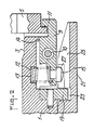
- reference 1 indicates part of a generally cylindrical coupling box having a central opening 3 for receiving an end of a rolling mill roll.
- the coupling box is mounted through a flexible joint to one end of a telescopic drive spindle (not shown).
- a drive pertains between the spindle and the roll.
- Reference 5 indicates a ring fitted around and projecting radially outwardly of the periphery of the roll end.
- the coupling box has at least one, and preferably of pair of, latches 9 which are pivotally mounted on the outside of the coupling box.
- Each latch is pivotally mounted on the coupling box by way of a pivot 10 intermediate the ends of the latch.
- a hook 11 At one end of the latch there is a hook 11 which enables the latch to fit around the outer edge of the ring 5 on the roll and thus prevent the roll from being withdrawn from the coupling box.
- At the opposite, inner, end of the latch there is a recess which receives one end of a coil spring 12 while the other end of the spring is located in a recess 13 formed in the wall of the coupling box.
- the spring is arranged to bias the latch in the anticlockwise direction, shown in Figure 2, against a stop 14.
- the coupling box On the outside of the latch, at the end to which the spring is attached, there is a button 15. Also on the coupling box, adjacent the button 15, there is an outwardly extending peg 19 which is aligned with the button 15. When the coupling box is provided with a pair of latches, it is convenient for there also to be a pair of pegs 19 and they are arranged to lie diametrically opposite to each other.
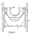
- a spindle support carrier is employed.
- the support carrier is indicated generally by reference 7 in Figure 1.
- the carrier is displaceable on a frame structure 8 in the direction of the axial length of the rolls.
- the support carrier has a saddle 20 which is capable of receiving and supporting the coupling box 1.
- hydraulic cylinders are provided for displacing the saddle vertically perpendicular to the axial length of the rolls. In this way, the saddle supporting a coupling box can be aligned with the end of a roll.
- the saddle has a forwardly projecting portion 2' and internally of this portion there is a groove 23 which extends around most of the internal periphery of the saddle. There is also a slot 25 which leads from the forward end of the projecting portion of the saddle to the recess 23.
- the carrier 7 When the mill is in use, and the rolls are being rotated, the carrier 7 is withdrawn away from the coupling box so as not to interfere with the coupling box or its spindle.
- the roll When, at roll changing time, the roll is to be removed from the coupling box, it is necessary to support the coupling box and, hence, the drive spindle, while the roll end is withdrawn from the coupling box.
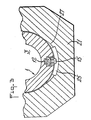
- the spindles When the roll is to be withdrawn from the coupling box, the spindles are indexed into a predetermined angular position and, at this position, the spindle support carrier 7 is moved forwards towards the roll so that, as it moves towards the roll, the peg 19 enters into, and moves along, the slot 25 into the recess 23. At this time the button 15 is positioned in the slot 25.
- the spring 12 is urging the button outwardly and the roll end is still latched in the coupling box.
- the spindle is then rotated relative to the support carrier so that the button 15 moves along an inclined surface 27 on the slot 25 of the carrier and this inclined surface forces the button to move inwardly against the action of the spring thus pivoting the latch about its pivot 10 to a position where the hook portion 11 of the latch is disconnected from the rind 5 at the roll end.
- the rotation of the coupling box is stopped and, with the coupling box supported on the support carrier, the spindle is retracted causing the carrier to be retracted due to the action of the peg 19 in the groove 23.
- the coupling box is drawn away from the roll end.
- a pair of support carriers are conveniently provided, one for each coupling of the two drive rolls.
Description
- This invention relates to rolling mills and, in particular, to the couplings by which the drive spindles are releasably connected to the ends of the driven rolls of the mill.
- It is well known that each driven roll of a rolling mill is connected at one end to its drive spindle by way of a coupling box which is connected through a joint to the spindle. The joint permits the spindles to be inclined to each other as the rolls are moved towards and away from each other and also permit rolls of different diameters to be employed. Clearly, when the mill is in use, care has to be taken that the roll end does not become withdrawn from the coupling box. At roll change time, however, the roll end has to be withdrawn from the coupling box and, in order to reduce the roll change time as much as possible, it is desirable that the withdrawal of the roll end from the coupling box should be accomplished quickly.
- It is known from DE-A-1 527 724 to provide a rolling mill with a coupling box secured by latches to an end of a rolling mill roll, and to provide a support carrier having provision for releasing the latch to enable the roll end to be withdrawn from the coupling box when the coupling box is supported on the support carrier.
- It is an object of the present invention to provide means by which a coupling box can readily and rapidly release the end of the roll.
- The present invention resides in the combination of a drive spindle having a coupling box at one end, the box being arranged to receive one end of a rolling mill roll and having a latch pivotally mounted on the coupling box and biased to its latching position to engage and prevent withdrawal of a roll end inserted in the coupling box, and a support carrier displaceable to support the coupling box, characterised in that angular rotation of the coupling box relative to the support carrier causes a cam surface on the support carrier to progressively engage a part of the latch to displace the latch to a position to release the roll end.
- The coupling box is latched on to the roll end and this serves to prevent axial withdrawal of the roll end from the coupling box. When, however, it is desirable to withdraw the roll end from the coupling box, as at roll changing time, the displaceable support carrier is displaced to a position where it supports the coupling box and, in this position, relative movement between the coupling box and the support carrier releases the latch to enable the roll end to be withdrawn from the coupling box. The carrier supports the coupling box until another roll end is introduced into the coupling box and, thereafter, the latch is reengaged on to the roll end to prevent withdrawal of the roll end from the coupling box.
- Conveniently, the latch is pivotally mounted on the coupling box and it is biased to its latching position. The latch remains biased into its latching position while the support carrier is moved into a position where it can support the coupling box and then engagement between a part of the latch and the support carrier causes the latch to pivot against the bias to release the roll end.
- Conveniently, it is the relative angular rotation between the coupling box and the support carrier which causes the cam surface on the coupling box to progressively engage said part of the latch to displace the latch to the position in which the roll end is released. Furthermore, a part of the coupling box is held fast relative to the carrier so that withdrawal of the spindle causes the coupling box to be displaced away from the end of the roll.
- In order that the invention may be more readily understood, it will now be described, by way of example only, with reference to the accompanying drawings, in which:
- Figure 1 is an end view of part of a spindle support carrier;
- Figure 2 is a sectional view of part of the spindle support carrier and part of the coupling box provided with a latch for latching a roll in the coupling box; and
- Figure 3 is a scrap view showing part of the coupling box and the support carrier.
- Referring to Figure 2,
reference 1 indicates part of a generally cylindrical coupling box having acentral opening 3 for receiving an end of a rolling mill roll. The coupling box is mounted through a flexible joint to one end of a telescopic drive spindle (not shown). When the roll end is firmly located in the central opening in the coupling box, a drive pertains between the spindle and the roll. Reference 5 indicates a ring fitted around and projecting radially outwardly of the periphery of the roll end. - The coupling box has at least one, and preferably of pair of,
latches 9 which are pivotally mounted on the outside of the coupling box. Each latch is pivotally mounted on the coupling box by way of apivot 10 intermediate the ends of the latch. At one end of the latch there is ahook 11 which enables the latch to fit around the outer edge of the ring 5 on the roll and thus prevent the roll from being withdrawn from the coupling box. At the opposite, inner, end of the latch there is a recess which receives one end of acoil spring 12 while the other end of the spring is located in arecess 13 formed in the wall of the coupling box. The spring is arranged to bias the latch in the anticlockwise direction, shown in Figure 2, against astop 14. On the outside of the latch, at the end to which the spring is attached, there is abutton 15. Also on the coupling box, adjacent thebutton 15, there is an outwardly extendingpeg 19 which is aligned with thebutton 15. When the coupling box is provided with a pair of latches, it is convenient for there also to be a pair ofpegs 19 and they are arranged to lie diametrically opposite to each other. - At roll changing time, it is necessary to support the coupling box, and hence the end of the drive spindle, while the roll end is withdrawn from the coupling box. To this end, a spindle support carrier is employed. The support carrier is indicated generally by
reference 7 in Figure 1. The carrier is displaceable on a frame structure 8 in the direction of the axial length of the rolls. The support carrier has asaddle 20 which is capable of receiving and supporting thecoupling box 1. In addition to being displaceable in the direction of the length of the rolls, hydraulic cylinders are provided for displacing the saddle vertically perpendicular to the axial length of the rolls. In this way, the saddle supporting a coupling box can be aligned with the end of a roll. The saddle has a forwardly projecting portion 2' and internally of this portion there is agroove 23 which extends around most of the internal periphery of the saddle. There is also aslot 25 which leads from the forward end of the projecting portion of the saddle to therecess 23. - When the mill is in use, and the rolls are being rotated, the
carrier 7 is withdrawn away from the coupling box so as not to interfere with the coupling box or its spindle. When, at roll changing time, the roll is to be removed from the coupling box, it is necessary to support the coupling box and, hence, the drive spindle, while the roll end is withdrawn from the coupling box. When the roll is to be withdrawn from the coupling box, the spindles are indexed into a predetermined angular position and, at this position, thespindle support carrier 7 is moved forwards towards the roll so that, as it moves towards the roll, thepeg 19 enters into, and moves along, theslot 25 into therecess 23. At this time thebutton 15 is positioned in theslot 25. Thespring 12 is urging the button outwardly and the roll end is still latched in the coupling box. The spindle is then rotated relative to the support carrier so that thebutton 15 moves along aninclined surface 27 on theslot 25 of the carrier and this inclined surface forces the button to move inwardly against the action of the spring thus pivoting the latch about itspivot 10 to a position where thehook portion 11 of the latch is disconnected from the rind 5 at the roll end. In this position, the rotation of the coupling box is stopped and, with the coupling box supported on the support carrier, the spindle is retracted causing the carrier to be retracted due to the action of thepeg 19 in thegroove 23. The coupling box is drawn away from the roll end. A pair of support carriers are conveniently provided, one for each coupling of the two drive rolls. When a new roll has been fitted into the mill, the coupling box, while still supported on the support carrier, is accurately aligned with the roll end. The coupling box is then moved forwards on to the end of the roll and, thereafter, the coupling box is rotated to allow thebutton 15 to move down the inclined surface, thus allowing thelatch 9 to pivot into the position where it hooks over the ring 5 on the roll to retain the roll in the coupling box.
Claims (3)
Applications Claiming Priority (2)
| Application Number | Priority Date | Filing Date | Title |
|---|---|---|---|
| GB8510976 | 1985-04-30 | ||
| GB858510976A GB8510976D0 (en) | 1985-04-30 | 1985-04-30 | Rolling mills |
Publications (3)
| Publication Number | Publication Date |
|---|---|
| EP0200544A2 EP0200544A2 (en) | 1986-11-05 |
| EP0200544A3 EP0200544A3 (en) | 1987-05-20 |
| EP0200544B1 true EP0200544B1 (en) | 1989-04-19 |
Family
ID=10578445
Family Applications (1)
| Application Number | Title | Priority Date | Filing Date |
|---|---|---|---|
| EP19860303280 Expired EP0200544B1 (en) | 1985-04-30 | 1986-04-30 | Improvements relating to rolling mills |
Country Status (3)
| Country | Link |
|---|---|
| EP (1) | EP0200544B1 (en) |
| DE (1) | DE3662843D1 (en) |
| GB (1) | GB8510976D0 (en) |
Family Cites Families (4)
| Publication number | Priority date | Publication date | Assignee | Title |
|---|---|---|---|---|
| DE7344551U (en) * | 1977-07-14 | Schloemann-Siemag Ag, 4000 Duesseldorf | Flat pin coupling for roll stands | |
| BE569805A (en) * | 1957-07-26 | |||
| DE1945612U (en) * | 1960-09-10 | 1966-09-08 | Siemag Siegener Masch Bau | HEADSTAIR FOR ROLLING MILLS. |
| DE1527724A1 (en) * | 1966-12-07 | 1970-02-12 | Schloemann Ag | Rolling mill coupling, especially for heavy rolling mill drives |
-
1985
- 1985-04-30 GB GB858510976A patent/GB8510976D0/en active Pending
-
1986
- 1986-04-30 EP EP19860303280 patent/EP0200544B1/en not_active Expired
- 1986-04-30 DE DE8686303280T patent/DE3662843D1/en not_active Expired
Also Published As
| Publication number | Publication date |
|---|---|
| DE3662843D1 (en) | 1989-05-24 |
| EP0200544A3 (en) | 1987-05-20 |
| EP0200544A2 (en) | 1986-11-05 |
| GB8510976D0 (en) | 1985-06-05 |
Similar Documents
| Publication | Publication Date | Title |
|---|---|---|
| JP2558229B2 (en) | Roll-shaped article loading device and loading method | |
| US6287059B1 (en) | Machine tool clamping device | |
| CA2214071A1 (en) | An adapter for rotatably supporting a yarn carrier in a winding assembly of a yarn processing machine | |
| US4676448A (en) | Winding machine for winding and/or unwinding web-like guided materials | |
| US4230286A (en) | Core holder for reeling | |
| US4655275A (en) | Tool, particularly an injection mold | |
| EP0200544B1 (en) | Improvements relating to rolling mills | |
| EP0390211A3 (en) | Disk-cassette loading mechanism | |
| US4910860A (en) | Toolholder for a machine tool | |
| US4199963A (en) | Overload couplings | |
| US4174077A (en) | Core holder for reeling | |
| CA2041715A1 (en) | Device for temporarily axially immobilizing a shaft in a body such as a steering column casing tube | |
| AU657762B2 (en) | Tool for mounting to a parcel containing a coil of a continuous flexible object | |
| CN216829743U (en) | Thin-wall pipe spare excircle processing centre gripping frock | |
| JPS5852132A (en) | Supporting means for sheet winding and unwinding core tube | |
| JPS5853132Y2 (en) | Dummy block attaching/detaching device in extrusion processing machine | |
| JPH0218045Y2 (en) | ||
| JPS6013534Y2 (en) | Roll chock device for rolling mill | |
| KR200194311Y1 (en) | Fixing device of rubber slieve | |
| JPH0143416Y2 (en) | ||
| JPS583633Y2 (en) | tool clamp device | |
| JPH0531901Y2 (en) | ||
| JP2571853Y2 (en) | Connection bracket | |
| US3293842A (en) | Spindle mounted automatically doffable warp bobbin | |
| KR960008488Y1 (en) | Heli coil inserting device |
Legal Events
| Date | Code | Title | Description |
|---|---|---|---|
| PUAI | Public reference made under article 153(3) epc to a published international application that has entered the european phase |
Free format text: ORIGINAL CODE: 0009012 |
|
| AK | Designated contracting states |
Kind code of ref document: A2 Designated state(s): DE GB IT SE |
|
| PUAL | Search report despatched |
Free format text: ORIGINAL CODE: 0009013 |
|
| AK | Designated contracting states |
Kind code of ref document: A3 Designated state(s): DE GB IT SE |
|
| 17P | Request for examination filed |
Effective date: 19870626 |
|
| 17Q | First examination report despatched |
Effective date: 19880601 |
|
| GRAA | (expected) grant |
Free format text: ORIGINAL CODE: 0009210 |
|
| AK | Designated contracting states |
Kind code of ref document: B1 Designated state(s): DE GB IT SE |
|
| REF | Corresponds to: |
Ref document number: 3662843 Country of ref document: DE Date of ref document: 19890524 |
|
| ITF | It: translation for a ep patent filed |
Owner name: STUDIO CONS. BREVETTUALE S.R.L. |
|
| PLBE | No opposition filed within time limit |
Free format text: ORIGINAL CODE: 0009261 |
|
| STAA | Information on the status of an ep patent application or granted ep patent |
Free format text: STATUS: NO OPPOSITION FILED WITHIN TIME LIMIT |
|
| 26N | No opposition filed | ||
| ITTA | It: last paid annual fee | ||
| PGFP | Annual fee paid to national office [announced via postgrant information from national office to epo] |
Ref country code: GB Payment date: 19940425 Year of fee payment: 9 |
|
| PGFP | Annual fee paid to national office [announced via postgrant information from national office to epo] |
Ref country code: DE Payment date: 19940428 Year of fee payment: 9 |
|
| PGFP | Annual fee paid to national office [announced via postgrant information from national office to epo] |
Ref country code: SE Payment date: 19940429 Year of fee payment: 9 |
|
| EAL | Se: european patent in force in sweden |
Ref document number: 86303280.1 |
|
| PG25 | Lapsed in a contracting state [announced via postgrant information from national office to epo] |
Ref country code: GB Effective date: 19950430 |
|
| PG25 | Lapsed in a contracting state [announced via postgrant information from national office to epo] |
Ref country code: SE Effective date: 19950501 |
|
| GBPC | Gb: european patent ceased through non-payment of renewal fee |
Effective date: 19950430 |
|
| PG25 | Lapsed in a contracting state [announced via postgrant information from national office to epo] |
Ref country code: DE Effective date: 19960103 |
|
| EUG | Se: european patent has lapsed |
Ref document number: 86303280.1 |
|
| PG25 | Lapsed in a contracting state [announced via postgrant information from national office to epo] |
Ref country code: IT Free format text: LAPSE BECAUSE OF NON-PAYMENT OF DUE FEES;WARNING: LAPSES OF ITALIAN PATENTS WITH EFFECTIVE DATE BEFORE 2007 MAY HAVE OCCURRED AT ANY TIME BEFORE 2007. THE CORRECT EFFECTIVE DATE MAY BE DIFFERENT FROM THE ONE RECORDED. Effective date: 20050430 |