EP0200535A2 - Überprüfung eines von der Oberfläche aus gesteuerten Untertagsteuergerätes - Google Patents
Überprüfung eines von der Oberfläche aus gesteuerten Untertagsteuergerätes Download PDFInfo
- Publication number
- EP0200535A2 EP0200535A2 EP86303259A EP86303259A EP0200535A2 EP 0200535 A2 EP0200535 A2 EP 0200535A2 EP 86303259 A EP86303259 A EP 86303259A EP 86303259 A EP86303259 A EP 86303259A EP 0200535 A2 EP0200535 A2 EP 0200535A2
- Authority
- EP
- European Patent Office
- Prior art keywords
- valve
- subsurface
- signal
- data
- state
- Prior art date
- Legal status (The legal status is an assumption and is not a legal conclusion. Google has not performed a legal analysis and makes no representation as to the accuracy of the status listed.)
- Granted
Links
Images

Classifications
-
- G—PHYSICS
- G08—SIGNALLING
- G08C—TRANSMISSION SYSTEMS FOR MEASURED VALUES, CONTROL OR SIMILAR SIGNALS
- G08C25/00—Arrangements for preventing or correcting errors; Monitoring arrangements
- G08C25/04—Arrangements for preventing or correcting errors; Monitoring arrangements by recording transmitted signals
-
- E—FIXED CONSTRUCTIONS
- E21—EARTH OR ROCK DRILLING; MINING
- E21B—EARTH OR ROCK DRILLING; OBTAINING OIL, GAS, WATER, SOLUBLE OR MELTABLE MATERIALS OR A SLURRY OF MINERALS FROM WELLS
- E21B34/00—Valve arrangements for boreholes or wells
- E21B34/16—Control means therefor being outside the borehole
-
- E—FIXED CONSTRUCTIONS
- E21—EARTH OR ROCK DRILLING; MINING
- E21B—EARTH OR ROCK DRILLING; OBTAINING OIL, GAS, WATER, SOLUBLE OR MELTABLE MATERIALS OR A SLURRY OF MINERALS FROM WELLS
- E21B47/00—Survey of boreholes or wells
- E21B47/12—Means for transmitting measuring-signals or control signals from the well to the surface, or from the surface to the well, e.g. for logging while drilling
- E21B47/13—Means for transmitting measuring-signals or control signals from the well to the surface, or from the surface to the well, e.g. for logging while drilling by electromagnetic energy, e.g. radio frequency
-
- E—FIXED CONSTRUCTIONS
- E21—EARTH OR ROCK DRILLING; MINING
- E21B—EARTH OR ROCK DRILLING; OBTAINING OIL, GAS, WATER, SOLUBLE OR MELTABLE MATERIALS OR A SLURRY OF MINERALS FROM WELLS
- E21B47/00—Survey of boreholes or wells
- E21B47/26—Storing data down-hole, e.g. in a memory or on a record carrier
-
- Y—GENERAL TAGGING OF NEW TECHNOLOGICAL DEVELOPMENTS; GENERAL TAGGING OF CROSS-SECTIONAL TECHNOLOGIES SPANNING OVER SEVERAL SECTIONS OF THE IPC; TECHNICAL SUBJECTS COVERED BY FORMER USPC CROSS-REFERENCE ART COLLECTIONS [XRACs] AND DIGESTS
- Y10—TECHNICAL SUBJECTS COVERED BY FORMER USPC
- Y10T—TECHNICAL SUBJECTS COVERED BY FORMER US CLASSIFICATION
- Y10T137/00—Fluid handling
- Y10T137/402—Distribution systems involving geographic features
-
- Y—GENERAL TAGGING OF NEW TECHNOLOGICAL DEVELOPMENTS; GENERAL TAGGING OF CROSS-SECTIONAL TECHNOLOGIES SPANNING OVER SEVERAL SECTIONS OF THE IPC; TECHNICAL SUBJECTS COVERED BY FORMER USPC CROSS-REFERENCE ART COLLECTIONS [XRACs] AND DIGESTS
- Y10—TECHNICAL SUBJECTS COVERED BY FORMER USPC
- Y10T—TECHNICAL SUBJECTS COVERED BY FORMER US CLASSIFICATION
- Y10T137/00—Fluid handling
- Y10T137/8158—With indicator, register, recorder, alarm or inspection means
- Y10T137/8225—Position or extent of motion indicator
- Y10T137/8242—Electrical
Definitions
- This invention relates in general to the art of extracting a liquid fossil fuel (oil, gas or liquified coal) from beneath the earth's surface and other such underground activities.
- Subsurface actuators are used in the drilling, testing, completing, and producing phases of oil field activity.
- the primary application of this invention is to subsurface safety valves for installation in wells that are already producing oil or gas.
- the principles of the invention have other applications as well.
- the present invention is directed to an arrangement for verifying correct operation or determining intermittent or marginal performance, of a subsurface device, such as a valve, that is controlled by an electromagnetic signal transmitted by a control station located at the earth's surface, such as at a ground station or on a well platform in a sea.
- a subsurface device such as a valve
- a control station located at the earth's surface, such as at a ground station or on a well platform in a sea.
- a significant problem with valves or other actuating devices installed downhole is that it is not possible, to know for certain whether a pa l cicular installation is working properly.
- the low frequency communication channel between the earth's surface and the subsurface valve is a noisy one (low S/N ratio). Not all control information transmitted at the surface is properly received and acted upon.
- the subsurface installed device may be called upon many times to respond to various control signals transmitted at the earth's surface for opening and closing a valve. Later, when the valve or other device is removed from its subsurface installation, it is not known whether the device responded properly to the various signals transmitted to it. In other words, there is no presently known system for verifying that a transmission of control information from the surface to a downhole installation was effective.
- U.S. Patent 4,216,536 Verification of data transmitted from a subsurface installation to the earth's surface was addressed in U.S. Patent 4,216,536 - More (August 5, 1980).
- U.S. Patent 4,216,536 there is described a system for storing downhole data (measurements of various physical parameters at the downhole location) sensed by a subsurface device, transmitting that data to the surface whereat it is received and stored. Later, after retrieving the subsurface device from its downhole installation, the data stored downhole is read from storage and compared with the data received and stored at the surface. Thus, the effectiveness of the transmission of data from the downhole installation to the earth's surface can be determined.
- the problem remains as to how to verify correct operation or determine intermittent or marginal performance of a downhole actuating device, such as a valve, in'response to control signals transmitted from the earth's surface to the downhole device over a noisy.communication channel.
- a downhole actuating device such as a valve
- This invention provides an arrangement including apparatus and method for providing effective verification of the operation of surface controlled actuating devices such as valves installed subsurface. Use of this invention insures that nonfunctional or marginally operating downhole actuators are reliably detected so that corrective steps can be taken, if necessary.
- the invention is particularly applicable to multiple well head oil or gas field installations wherein valves are installed in each of the wells. Control of all valves is from a surface control(led) system which transmits signals addressing any particular valve to be actuated.
- the surface control system includes a surface control station installed at a convenient surface location. It can be operated locally via a key pad input or remotely via a remote control system.
- the surface control system includes a transmitter at the earth's surface for transmitting signals to a receiver associated with the subsurface installed actuable device.
- the subsurface actuating device in the preferred embodiment, is a subsurface actuating valve (SAV).
- SAV subsurface actuating valve
- the SAV is most effectively installed in a tubing nipple below the packer of a well.
- the valve mechanism controls the flow of oil or gas from the casing of the well below the packer into the tubing.
- Electromagnetic signals transmitted by the transmitter of the surface control system are sensed by an antenna and processed by a receiver which includes means for amplifying and filtering signals from the antenna. Ultimately, these signals are converted into a digital data format and processed by a microprocessor operating under program control to decode a received message.
- the microprocessor determines whether a particular received signal is intended for its associated valve (as opposed to some other valve), and if so, what valve response is being commanded.
- a real time clock provides a time reference that can be tagged to the recording of received commands.
- the microprocessor determines a received signal to be a valve command for its associated SAV, it actuates a valve control which in turn actuates the valve to assume the commanded state.
- a sensor is provided at the downhole location for mechanically sensing valve motion and providing a signal indicative of the valve state. This signal is input to the microprocessor for ultimate storage in a bulk memory along with time information from the real time clock and information about the received signal, such as measured signal to noise (S/N) ratio.
- S/N measured signal to noise
- the control information stored in the bulk memory is read via a communications interface by the surface control system.
- the surface control system correlates data, previously stored at the surface relating to its transmissions to the various valves, with control information read from the bulk memory of each valve or valves and determines the effectiveness of remote actuation of such valve or valves.
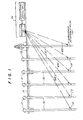
- FIGURE 1 there is schematically shown an oil or gas production field having a plurality of well heads 10.
- a well bore 12 beneath the surface of the earth represented by ground level 14.
- ground level 14 The invention is equally applicable to a sea installation in which the earth's surface is represented by a sea level.
- a subsurface actuating valve (SAV), referred to generally by reference numeral 16 is installed downhole in each of well bores 12.
- the SAVs 16 are controlled by signals transmitted by a transmitter 18.
- the electromagnetic signals transmitted by transmitter 18 are symbolized by lines 22.
- FIGURE 2 there is shown a schematic diagram of the general arrangement of a SAV 16.
- SAV 16 is shown installed downhole in a well bore 12.
- the installation of SAV 16 within well bore 12 is such that it is wire line retrievable. It is installed in a tubing nipple 28 below a packer 30.
- a valve mechanism 32 controls the flow of produced fluids from inside a casing 34 of the well to the inside of the tubing nipple 28.
- a lock 36 is positioned above valve mechanism 32 to hold the assembly in the tubing nipple.
- Signals transmitted by transmitter 18 at the earth's surface are picked up by an antenna 38.
- the signals are decoded by an electronic system 40 which determines whether a received signal is intended to command this particular valve as opposed to some other valve, and if so, what valve control is being commanded.
- Power for SAV 16 is provided by a battery system 42 which could include a single or multiple batteries. It can even include a secondary battery charged by a device for extracting energy from the flow of fluids produced by the well.
- a proximity sensor 44 is positioned so as to sense movement of a moving part of valve mechanism 32. Sensor 44 provides a signal to electronic system 40 indicative of the state of valve mechanism 32. While in this preferred embodiment a physical sensor of valve position is provided, it will be recognized that the state of the valve can be sensed indirectly by sensing, for example, fluid flow through the valve. This state information is recorded by electronic system 40 and saved for later use when SAV 16 is extracted from its downhole installation.
- the various parts of SAV 16 are housed within a pressure housing 46 for their protection.
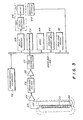
- FIGURE 3 there is shown a block diagram of various electronic portions of SAV 16. Aside from antenna 38, valve mechanism 32, and proximity sensor 44, the other blocks shown in FIGURE 3 are part of electronic system 40 shown in FIGURE 2.
- Antenna 38 includes a magnetic core 48 wrapped with a winding 50.
- Electromagnetic signals from transmitter 18 are received by antenna 38.
- the electromagnetic signal induces an electrical signal on leads 52 which are amplified by a differential amplifier 54 acting as a preamplifier.
- An output signal from amplifier 54 is filtered by a bandpass filter 56 and further amplified by an amplifier 58.
- the analog signal output from amplifier 58 is converted into a digital data format by an A/D converter 60.-
- the resulting data from A/D converter 60 is coupled to a data bus 62.
- Bandpass filter 56 restricts signals flowing through it to a frequency range of signals transmitted by transmitter 18.
- microprocessor 64 coupled to data bus 62. It is presently preferred that microprocessor 64 be a low power device such as, for example, an RCA 1802 or 1805, an NSC 800 (National Semiconductor), or Motorola 146805 or MC 68HCil. Each of the aforementioned microprocessor chips is a CMOS device which operates on a 8-bit bus structure. Microprocessor 64 operates according to a program code stored in program memory of a read only memory (ROM) 66, also coupled to data bus 62. Scratch pad memory is provided by a random access memory (RAM) 68, and a real time clock 70, coupled to data bus 62, provides a real time signal.
- ROM read only memory
- RAM random access memory
- the clock is synchronized at initialization of SAV 16 before downhole installation to a corresponding real time clock 72 (shown in FIGURE 4) in surface control system 26.
- Input to SAV 16 at the time of initialization is by means of a communications interface 74 coupled to data bus 62 (FIGURE 3) and a corresponding communications interface 76 of surface control system 26 (FIGURE 4).
- communication interfaces 74 and 76 are electrically coupled either directly or indirectly via some other communication channel such as a radio channel, optical interface, etc.
- microprocessor 64 determines that a valve actuation is necessary, it sends a signal to a valve control 78 of valve mechanism 32 which in turn actuates a valve 80 of valve mechanism 32.
- Valve actuation is sensed by proximity sensor 44 which provides a signal to data bus 62.
- a bulk memory 82 is provided for storing data as to attempted and actual valve actuations along with other data related to a valve actuation command, such as time according to real time clock 72, signal to noise (S/N) ratio of a received signal, etc.
- microprocessor 64 can determine whether or not it is receiving commands directed to its specific channel number to open or close its associated valve. If it should determine that the valve is to be opened, microprocessor 64 sends the appropriate signal to valve control 78. If nicroprocessor 64 should determine that the valve is to be closed, it sends the appropriate signal to valve control 78. If no signals are received at all or if transmission from the surface ceased, the valve would be commanded by microprocessor 64 to close or remain closed.
- microprocessor 64 Whenever any of these commands or events are recognized, microprocessor 64 also reads real time clock 70. Furthermore, it calculates a measure of the signal-to-noise (S/N) ratio of the signal being received from the surface. Time and S/N ratio data are then stored in bulk memory 82, downhole. This stored data indicates activity such as opening or closing of a valve, battery status, S/N ratio below a predetermined threshold, etc. Such activity data preferably would be identified by a four bit . digital code. Also stored would be the date and time of day which preferably would constitute 24 bits of digital data. Signal strength data would preferably comprise 8 bits of recorded digital data.
- S/N signal-to-noise
- Stored data could also include information resulting from false recognitions as well as indications of low battery voltage and low S/N ratio of a received signal.
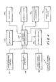
- FIGURE 4 there is shown a block diagram of surface control system 26.
- the heart of surface control system 26 is surface control station 24 which is also shown in FIGURE 1.
- a SAV 16 At such time as a SAV 16 becomes inoperative due, for example, to an exhausted battery or system malfunction, it would be retrieved by wire line and positioned at the surface such that its communication interface 74 could be connected with communications interface 76 of surface control system 26.
- Microprocessor 64 would be instructed to read out the contents of bulk memory 82 into surface control system 26.
- the surface control system 26 can be instructed via a key pad 84 to display or print, as represented by the representation 86 of an output device, the contents of bulk memories 82 and 88.
- Bulk memory 88 would have stored in it information about transmissions sent to the various SAVs 16. The information from bulk memory 88 relating to the particular SAV 16 being read would be correlated with the information read from bulk memory 82 of the SAV. Review of these two sets of data allows an assessment to be made of the ability of the valve assembly to receive commands from the surface and provides an indication of the inherent signal-to-noise ratio and its probability of error over the period of time the valve was installed.
- Surface control station 24 is preferably a computer implemented station which can receive inputs from key pad 84, a local control panel 90, and a remote control system 92 so that the surface control system 92 can be operated either locally or remotely.
- Surface control station 24 also accepts inputs from a well head control system 94 which includes emergency valve closure switches located in close proximity to their respective well heads.
- SAV 16 Before a SAV 16 is to be delivered to a well head for installation, communication interface 74 is connected to communications interface 76 of surface control system 26. SAV 16 is initialized and instructed to respond to signals of a particular command channel representing the well into which it is to be installed. In addition, the time of day is transmitted to the SAV 16. Preferably, the following information is stored in SAV 16 at the time of initialization. Initialization-4 bits: year 4 bits, month 4 bits, day 5 bits, hour 5 bits, minutes 6 bits, for a total of 24 bits or 3 bytes of information. Also, a channel number such as, for example, 1 of 27 channels is stored in a 5 bit data word.
- SAV 16 is prepared and run into the well by wire line, typically by using a lubricator on the well head into which the SAV 16 is being installed.
- wire line typically by using a lubricator on the well head into which the SAV 16 is being installed.
Landscapes
- Engineering & Computer Science (AREA)
- Physics & Mathematics (AREA)
- Geology (AREA)
- Life Sciences & Earth Sciences (AREA)
- Mining & Mineral Resources (AREA)
- Geochemistry & Mineralogy (AREA)
- Fluid Mechanics (AREA)
- General Life Sciences & Earth Sciences (AREA)
- Environmental & Geological Engineering (AREA)
- Geophysics (AREA)
- Remote Sensing (AREA)
- General Physics & Mathematics (AREA)
- Electromagnetism (AREA)
- Geophysics And Detection Of Objects (AREA)
- Arrangements For Transmission Of Measured Signals (AREA)
- Testing Of Devices, Machine Parts, Or Other Structures Thereof (AREA)
Applications Claiming Priority (2)
| Application Number | Priority Date | Filing Date | Title |
|---|---|---|---|
| US730705 | 1985-05-03 | ||
| US06/730,705 US4617960A (en) | 1985-05-03 | 1985-05-03 | Verification of a surface controlled subsurface actuating device |
Publications (3)
| Publication Number | Publication Date |
|---|---|
| EP0200535A2 true EP0200535A2 (de) | 1986-11-05 |
| EP0200535A3 EP0200535A3 (en) | 1988-06-22 |
| EP0200535B1 EP0200535B1 (de) | 1991-04-10 |
Family
ID=24936481
Family Applications (1)
| Application Number | Title | Priority Date | Filing Date |
|---|---|---|---|
| EP86303259A Expired - Lifetime EP0200535B1 (de) | 1985-05-03 | 1986-04-29 | Überprüfung eines von der Oberfläche aus gesteuerten Untertagsteuergerätes |
Country Status (6)
| Country | Link |
|---|---|
| US (1) | US4617960A (de) |
| EP (1) | EP0200535B1 (de) |
| JP (1) | JPS6233994A (de) |
| CA (1) | CA1255375A (de) |
| DE (1) | DE3678605D1 (de) |
| NO (1) | NO861716L (de) |
Cited By (12)
| Publication number | Priority date | Publication date | Assignee | Title |
|---|---|---|---|---|
| EP0476653A3 (en) * | 1990-09-20 | 1992-07-08 | Kawasaki Jukogyo Kabushiki Kaisha | Monitoring device for multiplex data communication equipment |
| EP0604156A1 (de) * | 1992-12-18 | 1994-06-29 | Halliburton Company | Drucksignal zur Fernsteuerung eines Bohrlochwerkzeuges |
| WO1996024749A1 (en) * | 1995-02-09 | 1996-08-15 | Baker Hughes Incorporated | Method and apparatus for the remote control and monitoring of production wells |
| US5597042A (en) * | 1995-02-09 | 1997-01-28 | Baker Hughes Incorporated | Method for controlling production wells having permanent downhole formation evaluation sensors |
| US5662165A (en) * | 1995-02-09 | 1997-09-02 | Baker Hughes Incorporated | Production wells having permanent downhole formation evaluation sensors |
| US5960883A (en) * | 1995-02-09 | 1999-10-05 | Baker Hughes Incorporated | Power management system for downhole control system in a well and method of using same |
| US6006832A (en) * | 1995-02-09 | 1999-12-28 | Baker Hughes Incorporated | Method and system for monitoring and controlling production and injection wells having permanent downhole formation evaluation sensors |
| US6065538A (en) * | 1995-02-09 | 2000-05-23 | Baker Hughes Corporation | Method of obtaining improved geophysical information about earth formations |
| US6192980B1 (en) * | 1995-02-09 | 2001-02-27 | Baker Hughes Incorporated | Method and apparatus for the remote control and monitoring of production wells |
| GB2382603A (en) * | 2001-11-28 | 2003-06-04 | Halliburton Energy Serv Inc | Electromagnetic telemetry actuated firing system for well perforating gun |
| WO2005124717A1 (de) | 2004-06-21 | 2005-12-29 | E. Hawle Armaturenwerke Gmbh | Ortungs- und betätigungseinrichtung für erdverlegte armaturen |
| GB2591839A (en) * | 2019-10-11 | 2021-08-11 | Schlumberger Technology Bv | Multiple valve control system and method |
Families Citing this family (46)
| Publication number | Priority date | Publication date | Assignee | Title |
|---|---|---|---|---|
| US4878053A (en) * | 1985-05-03 | 1989-10-31 | Develco, Inc. | Actuation method |
| US4708163A (en) * | 1987-01-28 | 1987-11-24 | Otis Engineering Corporation | Safety valve |
| US4839644A (en) * | 1987-06-10 | 1989-06-13 | Schlumberger Technology Corp. | System and method for communicating signals in a cased borehole having tubing |
| US4798247A (en) * | 1987-07-15 | 1989-01-17 | Otis Engineering Corporation | Solenoid operated safety valve and submersible pump system |
| US5343963A (en) * | 1990-07-09 | 1994-09-06 | Bouldin Brett W | Method and apparatus for providing controlled force transference to a wellbore tool |
| US5160925C1 (en) * | 1991-04-17 | 2001-03-06 | Halliburton Co | Short hop communication link for downhole mwd system |
| US5283768A (en) | 1991-06-14 | 1994-02-01 | Baker Hughes Incorporated | Borehole liquid acoustic wave transducer |
| US5299640A (en) * | 1992-10-19 | 1994-04-05 | Halliburton Company | Knife gate valve stage cementer |
| US5329956A (en) * | 1993-05-28 | 1994-07-19 | Combustion Engineering, Inc. | Pneumatic operated valve stroke timing |
| US6012015A (en) * | 1995-02-09 | 2000-01-04 | Baker Hughes Incorporated | Control model for production wells |
| US5966679A (en) * | 1995-10-30 | 1999-10-12 | Fisher Controls International, Inc. | Method of and apparatus for nonobtrusively obtaining on-line measurements of a process control device parameter |
| US5687098A (en) * | 1995-10-30 | 1997-11-11 | Fisher Controls International, Inc. | Device data acquisition |
| EP0877853A2 (de) * | 1996-02-03 | 1998-11-18 | Ocre (Scotland) Limited | Bohrlochventil |
| US6199629B1 (en) | 1997-09-24 | 2001-03-13 | Baker Hughes Incorporated | Computer controlled downhole safety valve system |
| US6466893B1 (en) | 1997-09-29 | 2002-10-15 | Fisher Controls International, Inc. | Statistical determination of estimates of process control loop parameters |
| US6804618B2 (en) * | 1997-09-29 | 2004-10-12 | Fisher Controls International, Llc | Detection and discrimination of instabilities in process control loops |
| US6192321B1 (en) | 1997-09-29 | 2001-02-20 | Fisher Controls International, Inc. | Method of and apparatus for deterministically obtaining measurements |
| US6075462A (en) * | 1997-11-24 | 2000-06-13 | Smith; Harrison C. | Adjacent well electromagnetic telemetry system and method for use of the same |
| US6177882B1 (en) * | 1997-12-01 | 2001-01-23 | Halliburton Energy Services, Inc. | Electromagnetic-to-acoustic and acoustic-to-electromagnetic repeaters and methods for use of same |
| US6144316A (en) * | 1997-12-01 | 2000-11-07 | Halliburton Energy Services, Inc. | Electromagnetic and acoustic repeater and method for use of same |
| US6018501A (en) * | 1997-12-10 | 2000-01-25 | Halliburton Energy Services, Inc. | Subsea repeater and method for use of the same |
| US6160492A (en) * | 1998-07-17 | 2000-12-12 | Halliburton Energy Services, Inc. | Through formation electromagnetic telemetry system and method for use of the same |
| US6216784B1 (en) | 1999-07-29 | 2001-04-17 | Halliburton Energy Services, Inc. | Subsurface electro-hydraulic power unit |
| US6597175B1 (en) | 1999-09-07 | 2003-07-22 | Halliburton Energy Services, Inc. | Electromagnetic detector apparatus and method for oil or gas well, and circuit-bearing displaceable object to be detected therein |
| US6343649B1 (en) | 1999-09-07 | 2002-02-05 | Halliburton Energy Services, Inc. | Methods and associated apparatus for downhole data retrieval, monitoring and tool actuation |
| CA2389621A1 (en) | 1999-11-16 | 2001-05-25 | Schlumberger Canada Limited | Downhole valve |
| US7451809B2 (en) * | 2002-10-11 | 2008-11-18 | Weatherford/Lamb, Inc. | Apparatus and methods for utilizing a downhole deployment valve |
| CN104088622A (zh) * | 2003-02-14 | 2014-10-08 | 贝克休斯公司 | 在非钻井井眼操作期间检测井下条件的系统及操作方法 |
| GB0425008D0 (en) * | 2004-11-12 | 2004-12-15 | Petrowell Ltd | Method and apparatus |
| US8517113B2 (en) * | 2004-12-21 | 2013-08-27 | Schlumberger Technology Corporation | Remotely actuating a valve |
| US7738975B2 (en) * | 2005-10-04 | 2010-06-15 | Fisher-Rosemount Systems, Inc. | Analytical server integrated in a process control network |
| US8036760B2 (en) | 2005-10-04 | 2011-10-11 | Fisher-Rosemount Systems, Inc. | Method and apparatus for intelligent control and monitoring in a process control system |
| US7444191B2 (en) | 2005-10-04 | 2008-10-28 | Fisher-Rosemount Systems, Inc. | Process model identification in a process control system |
| US10262168B2 (en) | 2007-05-09 | 2019-04-16 | Weatherford Technology Holdings, Llc | Antenna for use in a downhole tubular |
| US8651174B2 (en) | 2007-05-16 | 2014-02-18 | Gulfstream Services, Inc. | Method and apparatus for dropping a pump down plug or ball |
| GB0720421D0 (en) | 2007-10-19 | 2007-11-28 | Petrowell Ltd | Method and apparatus for completing a well |
| GB0804306D0 (en) | 2008-03-07 | 2008-04-16 | Petrowell Ltd | Device |
| US8159365B2 (en) * | 2008-04-16 | 2012-04-17 | Hydril Usa Manufacturing Llc | Distributed databases for a well control drilling system |
| GB0822144D0 (en) | 2008-12-04 | 2009-01-14 | Petrowell Ltd | Flow control device |
| GB0914650D0 (en) | 2009-08-21 | 2009-09-30 | Petrowell Ltd | Apparatus and method |
| US9121250B2 (en) * | 2011-03-19 | 2015-09-01 | Halliburton Energy Services, Inc. | Remotely operated isolation valve |
| US20130054034A1 (en) * | 2011-08-30 | 2013-02-28 | Hydril Usa Manufacturing Llc | Method, device and system for monitoring subsea components |
| WO2020157829A1 (ja) * | 2019-01-29 | 2020-08-06 | 株式会社エイシン技研 | サーボ弁ユニット |
| US11231315B2 (en) * | 2019-09-05 | 2022-01-25 | Baker Hughes Oilfield Operations Llc | Acoustic detection of position of a component of a fluid control device |
| EP3901407B1 (de) * | 2020-04-24 | 2023-06-07 | Metrol Technology Ltd | Bohrlochinstallationen und unterirdische sicherheitsventile |
| GB2612075A (en) | 2021-10-21 | 2023-04-26 | Metrol Tech Ltd | Well installation electrical transmission systems |
Family Cites Families (12)
| Publication number | Priority date | Publication date | Assignee | Title |
|---|---|---|---|---|
| US3209323A (en) * | 1962-10-02 | 1965-09-28 | Texaco Inc | Information retrieval system for logging while drilling |
| US3865142A (en) * | 1970-05-19 | 1975-02-11 | Fmc Corp | Electric remote control system for underwater wells |
| US3697952A (en) * | 1970-06-08 | 1972-10-10 | Harbhajan Singh Hayre | Remote actuated pollution and oil flow control system |
| US3665955A (en) * | 1970-07-20 | 1972-05-30 | George Eugene Conner Sr | Self-contained valve control system |
| US3737845A (en) * | 1971-02-17 | 1973-06-05 | H Maroney | Subsurface well control apparatus and method |
| US3975674A (en) * | 1972-09-29 | 1976-08-17 | Mceuen Robert B | Geothermal exploration method utilizing electrical resistivity and seismic velocity |
| US3967201A (en) * | 1974-01-25 | 1976-06-29 | Develco, Inc. | Wireless subterranean signaling method |
| US3977245A (en) * | 1975-04-21 | 1976-08-31 | Geophysical Research Corporation | Down hole apparatus for sensing and storing values of physical parameters |
| US4216536A (en) * | 1978-10-10 | 1980-08-05 | Exploration Logging, Inc. | Transmitting well logging data |
| US4337829A (en) * | 1979-04-05 | 1982-07-06 | Tecnomare, S.P.A. | Control system for subsea well-heads |
| US4468665A (en) * | 1981-01-30 | 1984-08-28 | Tele-Drill, Inc. | Downhole digital power amplifier for a measurements-while-drilling telemetry system |
| US4337653A (en) * | 1981-04-29 | 1982-07-06 | Koomey, Inc. | Blowout preventer control and recorder system |
-
1985
- 1985-05-03 US US06/730,705 patent/US4617960A/en not_active Expired - Fee Related
-
1986
- 1986-04-29 EP EP86303259A patent/EP0200535B1/de not_active Expired - Lifetime
- 1986-04-29 DE DE8686303259T patent/DE3678605D1/de not_active Expired - Lifetime
- 1986-04-30 NO NO861716A patent/NO861716L/no unknown
- 1986-05-02 JP JP61101208A patent/JPS6233994A/ja active Pending
- 1986-05-02 CA CA000508258A patent/CA1255375A/en not_active Expired
Cited By (23)
| Publication number | Priority date | Publication date | Assignee | Title |
|---|---|---|---|---|
| EP0476653A3 (en) * | 1990-09-20 | 1992-07-08 | Kawasaki Jukogyo Kabushiki Kaisha | Monitoring device for multiplex data communication equipment |
| EP0604156A1 (de) * | 1992-12-18 | 1994-06-29 | Halliburton Company | Drucksignal zur Fernsteuerung eines Bohrlochwerkzeuges |
| WO1996024749A1 (en) * | 1995-02-09 | 1996-08-15 | Baker Hughes Incorporated | Method and apparatus for the remote control and monitoring of production wells |
| GB2302115A (en) * | 1995-02-09 | 1997-01-08 | Baker Hughes Inc | Method and apparatus for the remote control and monitoring of production wells |
| US5597042A (en) * | 1995-02-09 | 1997-01-28 | Baker Hughes Incorporated | Method for controlling production wells having permanent downhole formation evaluation sensors |
| US5662165A (en) * | 1995-02-09 | 1997-09-02 | Baker Hughes Incorporated | Production wells having permanent downhole formation evaluation sensors |
| US5706896A (en) * | 1995-02-09 | 1998-01-13 | Baker Hughes Incorporated | Method and apparatus for the remote control and monitoring of production wells |
| GB2302115B (en) * | 1995-02-09 | 1999-08-18 | Baker Hughes Inc | Method and apparatus for the remote control and monitoring of production wells |
| US5960883A (en) * | 1995-02-09 | 1999-10-05 | Baker Hughes Incorporated | Power management system for downhole control system in a well and method of using same |
| US5975204A (en) * | 1995-02-09 | 1999-11-02 | Baker Hughes Incorporated | Method and apparatus for the remote control and monitoring of production wells |
| US6006832A (en) * | 1995-02-09 | 1999-12-28 | Baker Hughes Incorporated | Method and system for monitoring and controlling production and injection wells having permanent downhole formation evaluation sensors |
| US6065538A (en) * | 1995-02-09 | 2000-05-23 | Baker Hughes Corporation | Method of obtaining improved geophysical information about earth formations |
| US6176312B1 (en) | 1995-02-09 | 2001-01-23 | Baker Hughes Incorporated | Method and apparatus for the remote control and monitoring of production wells |
| US6192980B1 (en) * | 1995-02-09 | 2001-02-27 | Baker Hughes Incorporated | Method and apparatus for the remote control and monitoring of production wells |
| US6209640B1 (en) | 1995-02-09 | 2001-04-03 | Baker Hughes Incorporated | Method of obtaining improved geophysical information about earth formations |
| US6253848B1 (en) | 1995-02-09 | 2001-07-03 | Baker Hughes Incorporated | Method of obtaining improved geophysical information about earth formations |
| US6302204B1 (en) | 1995-02-09 | 2001-10-16 | Baker Hughes Incorporated | Method of obtaining improved geophysical information about earth formations |
| GB2382603A (en) * | 2001-11-28 | 2003-06-04 | Halliburton Energy Serv Inc | Electromagnetic telemetry actuated firing system for well perforating gun |
| US6820693B2 (en) | 2001-11-28 | 2004-11-23 | Halliburton Energy Services, Inc. | Electromagnetic telemetry actuated firing system for well perforating gun |
| WO2005124717A1 (de) | 2004-06-21 | 2005-12-29 | E. Hawle Armaturenwerke Gmbh | Ortungs- und betätigungseinrichtung für erdverlegte armaturen |
| GB2591839A (en) * | 2019-10-11 | 2021-08-11 | Schlumberger Technology Bv | Multiple valve control system and method |
| GB2591839B (en) * | 2019-10-11 | 2023-01-18 | Schlumberger Technology Bv | Multiple valve control system and method |
| US11815922B2 (en) | 2019-10-11 | 2023-11-14 | Schlumberger Technology Corporation | Multiple valve control system and method |
Also Published As
| Publication number | Publication date |
|---|---|
| CA1255375A (en) | 1989-06-06 |
| EP0200535A3 (en) | 1988-06-22 |
| DE3678605D1 (de) | 1991-05-16 |
| JPS6233994A (ja) | 1987-02-13 |
| NO861716L (no) | 1986-11-04 |
| US4617960A (en) | 1986-10-21 |
| EP0200535B1 (de) | 1991-04-10 |
Similar Documents
| Publication | Publication Date | Title |
|---|---|---|
| EP0200535B1 (de) | Überprüfung eines von der Oberfläche aus gesteuerten Untertagsteuergerätes | |
| US6006832A (en) | Method and system for monitoring and controlling production and injection wells having permanent downhole formation evaluation sensors | |
| CA2226923C (en) | Power management system for downhole control system in a well and method of using same | |
| US5941307A (en) | Production well telemetry system and method | |
| AU697668B2 (en) | Method and apparatus for the remote control and monitoring of production wells | |
| US5730219A (en) | Production wells having permanent downhole formation evaluation sensors | |
| US5597042A (en) | Method for controlling production wells having permanent downhole formation evaluation sensors | |
| US6046685A (en) | Redundant downhole production well control system and method | |
| US5662165A (en) | Production wells having permanent downhole formation evaluation sensors | |
| US5803167A (en) | Computer controlled downhole tools for production well control | |
| US4783995A (en) | Logging tool | |
| CA2215628C (en) | Well control systems employing downhole network | |
| CA2187424C (en) | Method and apparatus for the remote control and monitoring of production wells | |
| AU734599B2 (en) | Computer controlled downhole tools for production well control |
Legal Events
| Date | Code | Title | Description |
|---|---|---|---|
| PUAI | Public reference made under article 153(3) epc to a published international application that has entered the european phase |
Free format text: ORIGINAL CODE: 0009012 |
|
| AK | Designated contracting states |
Kind code of ref document: A2 Designated state(s): DE FR GB NL |
|
| PUAL | Search report despatched |
Free format text: ORIGINAL CODE: 0009013 |
|
| AK | Designated contracting states |
Kind code of ref document: A3 Designated state(s): DE FR GB NL |
|
| 17P | Request for examination filed |
Effective date: 19881205 |
|
| 17Q | First examination report despatched |
Effective date: 19900110 |
|
| GRAA | (expected) grant |
Free format text: ORIGINAL CODE: 0009210 |
|
| AK | Designated contracting states |
Kind code of ref document: B1 Designated state(s): DE FR GB NL |
|
| PGFP | Annual fee paid to national office [announced via postgrant information from national office to epo] |
Ref country code: NL Payment date: 19910430 Year of fee payment: 6 |
|
| ET | Fr: translation filed | ||
| REF | Corresponds to: |
Ref document number: 3678605 Country of ref document: DE Date of ref document: 19910516 |
|
| PGFP | Annual fee paid to national office [announced via postgrant information from national office to epo] |
Ref country code: FR Payment date: 19910614 Year of fee payment: 6 |
|
| PGFP | Annual fee paid to national office [announced via postgrant information from national office to epo] |
Ref country code: DE Payment date: 19910627 Year of fee payment: 6 |
|
| PGFP | Annual fee paid to national office [announced via postgrant information from national office to epo] |
Ref country code: GB Payment date: 19910723 Year of fee payment: 6 |
|
| PLBE | No opposition filed within time limit |
Free format text: ORIGINAL CODE: 0009261 |
|
| STAA | Information on the status of an ep patent application or granted ep patent |
Free format text: STATUS: NO OPPOSITION FILED WITHIN TIME LIMIT |
|
| 26N | No opposition filed | ||
| PG25 | Lapsed in a contracting state [announced via postgrant information from national office to epo] |
Ref country code: GB Effective date: 19920429 |
|
| PG25 | Lapsed in a contracting state [announced via postgrant information from national office to epo] |
Ref country code: NL Effective date: 19921101 |
|
| NLV4 | Nl: lapsed or anulled due to non-payment of the annual fee | ||
| GBPC | Gb: european patent ceased through non-payment of renewal fee | ||
| PG25 | Lapsed in a contracting state [announced via postgrant information from national office to epo] |
Ref country code: FR Effective date: 19921230 |
|
| PG25 | Lapsed in a contracting state [announced via postgrant information from national office to epo] |
Ref country code: DE Effective date: 19930101 |
|
| REG | Reference to a national code |
Ref country code: FR Ref legal event code: ST |