EP0200400B1 - Sheathed composite blind rivet - Google Patents
Sheathed composite blind rivet Download PDFInfo
- Publication number
- EP0200400B1 EP0200400B1 EP86302669A EP86302669A EP0200400B1 EP 0200400 B1 EP0200400 B1 EP 0200400B1 EP 86302669 A EP86302669 A EP 86302669A EP 86302669 A EP86302669 A EP 86302669A EP 0200400 B1 EP0200400 B1 EP 0200400B1
- Authority
- EP
- European Patent Office
- Prior art keywords
- rivet
- sheath
- head
- mandrel
- tubular body
- Prior art date
- Legal status (The legal status is an assumption and is not a legal conclusion. Google has not performed a legal analysis and makes no representation as to the accuracy of the status listed.)
- Expired
Links
- 239000002131 composite material Substances 0.000 title claims description 5
- OKTJSMMVPCPJKN-UHFFFAOYSA-N Carbon Chemical compound [C] OKTJSMMVPCPJKN-UHFFFAOYSA-N 0.000 claims description 10
- 229910052799 carbon Inorganic materials 0.000 claims description 10
- 229920005989 resin Polymers 0.000 claims description 9
- 239000011347 resin Substances 0.000 claims description 9
- 239000011159 matrix material Substances 0.000 claims description 8
- 239000004033 plastic Substances 0.000 claims description 7
- 230000006835 compression Effects 0.000 claims description 3
- 238000007906 compression Methods 0.000 claims description 3
- 239000002184 metal Substances 0.000 claims 1
- 239000000835 fiber Substances 0.000 description 4
- 239000000463 material Substances 0.000 description 4
- 235000001674 Agaricus brunnescens Nutrition 0.000 description 2
- 229920000049 Carbon (fiber) Polymers 0.000 description 2
- 239000004917 carbon fiber Substances 0.000 description 2
- 230000000295 complement effect Effects 0.000 description 2
- 230000001186 cumulative effect Effects 0.000 description 2
- 230000000694 effects Effects 0.000 description 2
- 238000010438 heat treatment Methods 0.000 description 2
- 239000004634 thermosetting polymer Substances 0.000 description 2
- RTAQQCXQSZGOHL-UHFFFAOYSA-N Titanium Chemical compound [Ti] RTAQQCXQSZGOHL-UHFFFAOYSA-N 0.000 description 1
- 230000001154 acute effect Effects 0.000 description 1
- 230000015572 biosynthetic process Effects 0.000 description 1
- 239000007795 chemical reaction product Substances 0.000 description 1
- 230000001010 compromised effect Effects 0.000 description 1
- 238000012423 maintenance Methods 0.000 description 1
- 238000002407 reforming Methods 0.000 description 1
- 229910052719 titanium Inorganic materials 0.000 description 1
- 239000010936 titanium Substances 0.000 description 1
Images
Classifications
-
- F—MECHANICAL ENGINEERING; LIGHTING; HEATING; WEAPONS; BLASTING
- F16—ENGINEERING ELEMENTS AND UNITS; GENERAL MEASURES FOR PRODUCING AND MAINTAINING EFFECTIVE FUNCTIONING OF MACHINES OR INSTALLATIONS; THERMAL INSULATION IN GENERAL
- F16B—DEVICES FOR FASTENING OR SECURING CONSTRUCTIONAL ELEMENTS OR MACHINE PARTS TOGETHER, e.g. NAILS, BOLTS, CIRCLIPS, CLAMPS, CLIPS OR WEDGES; JOINTS OR JOINTING
- F16B19/00—Bolts without screw-thread; Pins, including deformable elements; Rivets
- F16B19/04—Rivets; Spigots or the like fastened by riveting
- F16B19/08—Hollow rivets; Multi-part rivets
- F16B19/10—Hollow rivets; Multi-part rivets fastened by expanding mechanically
- F16B19/1027—Multi-part rivets
- F16B19/1036—Blind rivets
- F16B19/1045—Blind rivets fastened by a pull - mandrel or the like
- F16B19/1054—Blind rivets fastened by a pull - mandrel or the like the pull-mandrel or the like being frangible
-
- F—MECHANICAL ENGINEERING; LIGHTING; HEATING; WEAPONS; BLASTING
- F16—ENGINEERING ELEMENTS AND UNITS; GENERAL MEASURES FOR PRODUCING AND MAINTAINING EFFECTIVE FUNCTIONING OF MACHINES OR INSTALLATIONS; THERMAL INSULATION IN GENERAL
- F16B—DEVICES FOR FASTENING OR SECURING CONSTRUCTIONAL ELEMENTS OR MACHINE PARTS TOGETHER, e.g. NAILS, BOLTS, CIRCLIPS, CLAMPS, CLIPS OR WEDGES; JOINTS OR JOINTING
- F16B19/00—Bolts without screw-thread; Pins, including deformable elements; Rivets
- F16B19/04—Rivets; Spigots or the like fastened by riveting
- F16B19/08—Hollow rivets; Multi-part rivets
- F16B19/10—Hollow rivets; Multi-part rivets fastened by expanding mechanically
- F16B19/1027—Multi-part rivets
Definitions
- the blind rivet of the instant invention is an improvement on the composite rivet disclosed in our prior US-A-4 478 544 which forms the basis for the prior art portion of claim 1.
- Carbon fibre reinforced materials are now widely used in the aircraft industry for airframe structural components.
- the use of carbon fibre reinforced resins in blind rivets has been limited by the difficulty of properly forming the blind head.
- One characteristic of composite materials utilising carbon fibres is that the material often exhibits a rough finish after reforming due to protrusion or breakage of the carbon fibres. While structural integrity of the material may not be compromised, the end product is abrasive and aesthetically unsatisfactory.
- the problem becomes acute since the blind head is exposed on the rear surface of the workpiece.
- the rivet of the present invention as characterised in claim 1 in that the carbon fibres and resin matrix of the blind head thereof are encapsulated in a tensioned sheath.
- the sheath is so formed as to control deflection and projection of the carbon fibres upon formation of the rivet head and to aid in creating and maintaining pretension on the rivet.
- compression of the resin matrix which is softened due to the application of heat, forms a radially extending rivet head that is integral with the shear portion of the rivet and which, when fully polymerised, forms a riveted connection that exhibits relatively high shear strength.
- the configuration of the sheath and the mandrel of the rivet aids the maintenance of clamp-up forces and ensures that the blind head portion of the carbon fibre reinforced matrix of the rivet is entirely covered and protected by the sheath.
- a rivet 10 in accordance with a constructed embodiment of the instant invention comprises a carbon fibre- reinforced resin matrix, preferably a "B"-stage thermoset resin preform 11 having a head portion 12, a shear portion 14, and a blind head forming portion 16.
- a mandrel 18 is disposed centrally of the preform 11 and has an anvil 20 at one end thereof and a tensioning stem 22 at the other end thereof.
- the mandrel 18 is journalled in a complementary aperture 24 that extends through the head, shear and head forming portions 12, 14 and 16, respectively, of the preform 11.
- the shear portion 14 of the rivet 10 is coextensive with the cumulative thickness of a pair of workpieces 30 and 32.
- the mandrel 18 is adapted to be pulled, after heating of the preform 11, by a tool (not shown) of conventional design resulting in deformation of head forming portion 16 of the rivet 10 into the mushroom configuration shown.
- the head forming portion 16, of the rivet 10 is encapsulated by a sheath 34, preferably Titanium or suitable plastic, which expands to the configuration of the blind head and completely covers said head eliminating protrusion of carbon fibers 36 that are impregnated or encapsulated in the resin matrix.
- the sheath 34 has a uniform external diameter prior to deformation but has an upper end portion 37 of reduced internal diameter that controls collapse and maintains a bias on the reformed resin matrix after deformation. It is to be noted that the thickened wall section 37 commences well above the workpiece 30 whereby the relatively thin section thereof accommodates radial deflection of the sheath 34 and helps define the ultimate truncated conical cross section of the upper portion 37 thereof.
- the mandrel 18 is provided with an annular groove 40 in the stem 22 thereof into which resin flows thereby tensioning the mandrel and locking it within the head forming portion 16 of the rivet 10.
- a breakoff groove 44 is provided in the stem 22 to facilitate removal of excess stem portion after setting of the rivet 10.
- a rivet 50 comprises a carbon fibre reinforced preform 51, preferably a "B"-stage thermoset resin, having a head portion 52 of any desired configuration, a shear portion 54, and a blind head forming portion 56.
- a centrally disposed mandrel 58 has a head or anvil 60 at one end thereof and a tensioning stem 62 at the other end thereof.
- the mandrel 58 is journalled in a complementary aperture 64 that extends through the head, shear and head forming portions 52, 54 and 56, respectively, of the rivet 50.
- the shear portion 54 of the rivet 50 is coextensive with the cumulative thickness of a pair of workpieces 70 and 72.
- the mandrel 58 is adapted to be pulled, after heating of the preform 51, by a tool (not shown) resulting in deformation of the head forming portion 56 of the rivet 50 into the mushroom configuration shown.
- the head forming portion 56, of the rivet 50 is encapsulated by a plastic sheath 74 which expands to the configuration of the blind head eliminating protrusion of carbon fibers 76 that are impregnated or encapsulated in the resin matrix.
- the sheath 74 has a thickened upper end portion 78 that effects controlled deformation thereof and is reformed into a conical configuration that maintains pretension on the rivet 50. It is to be noted that the sheath 74 extends entirely through the workpiece 70 and into a counterbore 80 in the workpiece 72.
- a breakoff groove 82 is provided in the stem 62 to facilitate removal of the excess stem portion after setting of the rivet 50.
Description
- The blind rivet of the instant invention is an improvement on the composite rivet disclosed in our prior US-A-4 478 544 which forms the basis for the prior art portion of
claim 1. - Carbon fibre reinforced materials are now widely used in the aircraft industry for airframe structural components. However, the use of carbon fibre reinforced resins in blind rivets has been limited by the difficulty of properly forming the blind head. One characteristic of composite materials utilising carbon fibres is that the material often exhibits a rough finish after reforming due to protrusion or breakage of the carbon fibres. While structural integrity of the material may not be compromised, the end product is abrasive and aesthetically unsatisfactory. When such material is employed in the reformable head of a blind rivet, the problem becomes acute since the blind head is exposed on the rear surface of the workpiece.
- Another problem that must be addressed is that plastic cold flow of the rivet tends to reduce clamp-up forces on a workpiece. Thus, pretensioning of the rivet is highly desirable to offset ultimate relaxation of the tensile forces.
- The aforesaid problems are solved by the rivet of the present invention as characterised in
claim 1 in that the carbon fibres and resin matrix of the blind head thereof are encapsulated in a tensioned sheath. The sheath is so formed as to control deflection and projection of the carbon fibres upon formation of the rivet head and to aid in creating and maintaining pretension on the rivet. In both disclosed embodiments of the invention, compression of the resin matrix, which is softened due to the application of heat, forms a radially extending rivet head that is integral with the shear portion of the rivet and which, when fully polymerised, forms a riveted connection that exhibits relatively high shear strength. The configuration of the sheath and the mandrel of the rivet aids the maintenance of clamp-up forces and ensures that the blind head portion of the carbon fibre reinforced matrix of the rivet is entirely covered and protected by the sheath. -
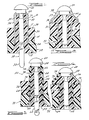
- Figure 1 is an elevational view, partially in cross section, of one embodiment of the blind rivet of the instant invention;
- Figure 2 is a view of the rivet of Figure 1 after tensioning of the rivet mandrel to form a blind head on the rivet;
- Figure 3 is a view similar to Figure 1 of another embodiment of the instant invention; and
- Figure 4 is a view of the rivet of Figure 3 after tensioning of the mandrel thereof to form a blind head on the rivet.
- As best seen in Fig. 1 of the drawings, a
rivet 10 in accordance with a constructed embodiment of the instant invention comprises a carbon fibre- reinforced resin matrix, preferably a "B"-stage thermoset resin preform 11 having ahead portion 12, ashear portion 14, and a blind head forming portion 16. Amandrel 18 is disposed centrally of the preform 11 and has ananvil 20 at one end thereof and atensioning stem 22 at the other end thereof. Themandrel 18 is journalled in acomplementary aperture 24 that extends through the head, shear andhead forming portions shear portion 14 of therivet 10 is coextensive with the cumulative thickness of a pair ofworkpieces 30 and 32. - As seen in Fig. 2 of the drawings, the
mandrel 18 is adapted to be pulled, after heating of the preform 11, by a tool (not shown) of conventional design resulting in deformation of head forming portion 16 of therivet 10 into the mushroom configuration shown. - In accordance with one feature of the instant invention, the head forming portion 16, of the
rivet 10 is encapsulated by asheath 34, preferably Titanium or suitable plastic, which expands to the configuration of the blind head and completely covers said head eliminating protrusion ofcarbon fibers 36 that are impregnated or encapsulated in the resin matrix. Thesheath 34 has a uniform external diameter prior to deformation but has an upper end portion 37 of reduced internal diameter that controls collapse and maintains a bias on the reformed resin matrix after deformation. It is to be noted that the thickened wall section 37 commences well above the workpiece 30 whereby the relatively thin section thereof accommodates radial deflection of thesheath 34 and helps define the ultimate truncated conical cross section of the upper portion 37 thereof. - From the foregoing it should be apparent that a smooth exterior surface is presented on the blind head which is not abrasive and is aesthetically pleasing. The
sheath 34 is mechanically collapsed by theanvil portion 20 of themandrel 18 in a manner that maintains the clamp-up force of therivet 10 in the event of plastic cold flow of theshear portion 14 thereof. - The
mandrel 18 is provided with an annular groove 40 in thestem 22 thereof into which resin flows thereby tensioning the mandrel and locking it within the head forming portion 16 of therivet 10. Abreakoff groove 44 is provided in thestem 22 to facilitate removal of excess stem portion after setting of therivet 10. - As seen in Figs. 3 and 4 of the drawings, a
rivet 50 comprises a carbon fibre reinforcedpreform 51, preferably a "B"-stage thermoset resin, having a head portion 52 of any desired configuration, a shear portion 54, and a blind head forming portion 56. A centrally disposedmandrel 58 has a head or anvil 60 at one end thereof and a tensioning stem 62 at the other end thereof. Themandrel 58 is journalled in acomplementary aperture 64 that extends through the head, shear and head forming portions 52, 54 and 56, respectively, of therivet 50. The shear portion 54 of therivet 50 is coextensive with the cumulative thickness of a pair ofworkpieces - As seen in Fig. 4 of the drawings, the
mandrel 58 is adapted to be pulled, after heating of thepreform 51, by a tool (not shown) resulting in deformation of the head forming portion 56 of therivet 50 into the mushroom configuration shown. - The head forming portion 56, of the
rivet 50, is encapsulated by aplastic sheath 74 which expands to the configuration of the blind head eliminating protrusion ofcarbon fibers 76 that are impregnated or encapsulated in the resin matrix. Thesheath 74 has a thickenedupper end portion 78 that effects controlled deformation thereof and is reformed into a conical configuration that maintains pretension on therivet 50. It is to be noted that thesheath 74 extends entirely through theworkpiece 70 and into acounterbore 80 in theworkpiece 72. Thus, plastic cold flow of the shear portion 54 of therivet 50 will not effect a reduction in clamp-up force of therivet 50 since tension induced by deformation of thesheath 74 will continue to pinch theworkpieces breakoff groove 82 is provided in the stem 62 to facilitate removal of the excess stem portion after setting of therivet 50.
Claims (3)
Applications Claiming Priority (2)
| Application Number | Priority Date | Filing Date | Title |
|---|---|---|---|
| US72778185A | 1985-04-26 | 1985-04-26 | |
| US727781 | 1985-04-26 |
Publications (2)
| Publication Number | Publication Date |
|---|---|
| EP0200400A1 EP0200400A1 (en) | 1986-11-05 |
| EP0200400B1 true EP0200400B1 (en) | 1988-09-21 |
Family
ID=24924040
Family Applications (1)
| Application Number | Title | Priority Date | Filing Date |
|---|---|---|---|
| EP86302669A Expired EP0200400B1 (en) | 1985-04-26 | 1986-04-10 | Sheathed composite blind rivet |
Country Status (6)
| Country | Link |
|---|---|
| EP (1) | EP0200400B1 (en) |
| JP (1) | JPS61248911A (en) |
| CA (1) | CA1275190C (en) |
| DE (1) | DE3660779D1 (en) |
| ES (1) | ES296524Y (en) |
| IL (1) | IL78313A0 (en) |
Cited By (1)
| Publication number | Priority date | Publication date | Assignee | Title |
|---|---|---|---|---|
| DE102006019156A1 (en) * | 2006-04-21 | 2007-10-25 | Universität Rostock | Blind rivet for aircraft construction, has hollow rivet body with setting head and rivet pin that has pin head arranged in setting head, where rivet body is formed from fiber-plastic composite in its socket-shaped area |
Families Citing this family (3)
| Publication number | Priority date | Publication date | Assignee | Title |
|---|---|---|---|---|
| US4859128A (en) * | 1985-04-26 | 1989-08-22 | Microdot Inc. | Sheathed composite blind rivet |
| US4838746A (en) * | 1988-01-12 | 1989-06-13 | Grumman Aerospace Corporation | Break-away rivet configuration |
| JP2792716B2 (en) * | 1990-06-04 | 1998-09-03 | 北川工業株式会社 | Fastener |
Family Cites Families (8)
| Publication number | Priority date | Publication date | Assignee | Title |
|---|---|---|---|---|
| US2410398A (en) * | 1945-08-24 | 1946-10-29 | Douglas Aircraft Co Inc | Rivet |
| FR1491499A (en) * | 1966-06-30 | 1967-08-11 | Cap especially for engine casing | |
| US3613495A (en) * | 1969-08-06 | 1971-10-19 | Henry J Podgursky | Fastener means including an interior expansible core |
| US3641865A (en) * | 1970-04-20 | 1972-02-15 | Blake Rivet Co | Sealing shear fastener |
| US4010519A (en) * | 1975-11-24 | 1977-03-08 | Shur-Lok Corporation | Fastener structures utilizing a thermoplastic adhesive |
| US4405256A (en) * | 1981-04-14 | 1983-09-20 | King John O Jun | Cushioned fastener joint |
| SE445166B (en) * | 1981-12-28 | 1986-06-09 | Goran Rutgersson | FIXING DEVICE AS A REINFORCEMENT RING SPECIFICALLY INTENDED FOR CANVAS OR OTHER THIN MATERIALS |
| US4478544A (en) * | 1982-06-04 | 1984-10-23 | Microdot Inc. | Composite rivet |
-
1986
- 1986-03-28 IL IL78313A patent/IL78313A0/en unknown
- 1986-04-03 CA CA000505806A patent/CA1275190C/en not_active Expired - Fee Related
- 1986-04-10 EP EP86302669A patent/EP0200400B1/en not_active Expired
- 1986-04-10 DE DE8686302669T patent/DE3660779D1/en not_active Expired
- 1986-04-24 JP JP61095841A patent/JPS61248911A/en active Granted
- 1986-04-25 ES ES1986296524U patent/ES296524Y/en not_active Expired
Cited By (1)
| Publication number | Priority date | Publication date | Assignee | Title |
|---|---|---|---|---|
| DE102006019156A1 (en) * | 2006-04-21 | 2007-10-25 | Universität Rostock | Blind rivet for aircraft construction, has hollow rivet body with setting head and rivet pin that has pin head arranged in setting head, where rivet body is formed from fiber-plastic composite in its socket-shaped area |
Also Published As
| Publication number | Publication date |
|---|---|
| IL78313A0 (en) | 1986-07-31 |
| ES296524U (en) | 1987-10-16 |
| EP0200400A1 (en) | 1986-11-05 |
| ES296524Y (en) | 1988-04-16 |
| DE3660779D1 (en) | 1988-10-27 |
| JPH0259323B2 (en) | 1990-12-12 |
| JPS61248911A (en) | 1986-11-06 |
| CA1275190C (en) | 1990-10-16 |
Similar Documents
| Publication | Publication Date | Title |
|---|---|---|
| US4877362A (en) | Sheathed composite blind rivet | |
| CA1303393C (en) | Sheathed composite blind rivet | |
| EP0203748B1 (en) | Composite rivet | |
| US4687396A (en) | One-piece composite rivet with deformable head portion and mandrel | |
| US4687398A (en) | Composite rivet with collar reinforced with circumferential fibers | |
| US4687397A (en) | Composite rivet with strippable mandrel | |
| US5361483A (en) | Composite fasteners and method for fastening structural components therewith | |
| US4407619A (en) | Blind fastener with deformable clamping means | |
| JP2965692B2 (en) | Swage fastener with strong separation collar | |
| US4627775A (en) | Blind fastener with grip compensating means | |
| US4595324A (en) | Impulse resistant blind fastener | |
| EP0063181B1 (en) | Composite buckling blind fastener | |
| US4687394A (en) | Composite rivet with deformable plastic locking ring | |
| EP0174406B1 (en) | Composite rivet | |
| US5359765A (en) | Rivet for composite material and composite material assembly process | |
| US4531871A (en) | Multigrip fastener | |
| US5049016A (en) | Swage fasteners with a high stand-off collar | |
| CA2050493A1 (en) | Fit up swage fastener with a variable and selectively high initial clamp pre-load and method | |
| US5620287A (en) | Fastener system with controlled clamping load | |
| US5171115A (en) | Swage collar with pintail and fastening system and method | |
| EP0200400B1 (en) | Sheathed composite blind rivet | |
| WO1987005672A1 (en) | Fastener for securing panels of composite materials | |
| US5580202A (en) | Crowned solid rivet | |
| GB2076493A (en) | Blind Fastener with Deformable Clamping Means | |
| RU2006692C1 (en) | Rivet for one-sided riveting |
Legal Events
| Date | Code | Title | Description |
|---|---|---|---|
| PUAI | Public reference made under article 153(3) epc to a published international application that has entered the european phase |
Free format text: ORIGINAL CODE: 0009012 |
|
| AK | Designated contracting states |
Kind code of ref document: A1 Designated state(s): DE FR GB IT |
|
| 17P | Request for examination filed |
Effective date: 19861006 |
|
| 17Q | First examination report despatched |
Effective date: 19870615 |
|
| GRAA | (expected) grant |
Free format text: ORIGINAL CODE: 0009210 |
|
| AK | Designated contracting states |
Kind code of ref document: B1 Designated state(s): DE FR GB IT |
|
| ITF | It: translation for a ep patent filed |
Owner name: MODIANO & ASSOCIATI S.R.L. |
|
| REF | Corresponds to: |
Ref document number: 3660779 Country of ref document: DE Date of ref document: 19881027 |
|
| ET | Fr: translation filed | ||
| PLBE | No opposition filed within time limit |
Free format text: ORIGINAL CODE: 0009261 |
|
| STAA | Information on the status of an ep patent application or granted ep patent |
Free format text: STATUS: NO OPPOSITION FILED WITHIN TIME LIMIT |
|
| 26N | No opposition filed | ||
| ITTA | It: last paid annual fee | ||
| PGFP | Annual fee paid to national office [announced via postgrant information from national office to epo] |
Ref country code: GB Payment date: 19940331 Year of fee payment: 9 |
|
| PGFP | Annual fee paid to national office [announced via postgrant information from national office to epo] |
Ref country code: DE Payment date: 19940408 Year of fee payment: 9 |
|
| PGFP | Annual fee paid to national office [announced via postgrant information from national office to epo] |
Ref country code: FR Payment date: 19940411 Year of fee payment: 9 |
|
| PG25 | Lapsed in a contracting state [announced via postgrant information from national office to epo] |
Ref country code: GB Effective date: 19950410 |
|
| GBPC | Gb: european patent ceased through non-payment of renewal fee |
Effective date: 19950410 |
|
| PG25 | Lapsed in a contracting state [announced via postgrant information from national office to epo] |
Ref country code: FR Effective date: 19951229 |
|
| REG | Reference to a national code |
Ref country code: FR Ref legal event code: ST |
|
| PG25 | Lapsed in a contracting state [announced via postgrant information from national office to epo] |
Ref country code: DE Effective date: 19970501 |
|
| PG25 | Lapsed in a contracting state [announced via postgrant information from national office to epo] |
Ref country code: IT Free format text: LAPSE BECAUSE OF NON-PAYMENT OF DUE FEES Effective date: 20050410 |