EP0200331B1 - Pressure regulator - Google Patents
Pressure regulator Download PDFInfo
- Publication number
- EP0200331B1 EP0200331B1 EP86302028A EP86302028A EP0200331B1 EP 0200331 B1 EP0200331 B1 EP 0200331B1 EP 86302028 A EP86302028 A EP 86302028A EP 86302028 A EP86302028 A EP 86302028A EP 0200331 B1 EP0200331 B1 EP 0200331B1
- Authority
- EP
- European Patent Office
- Prior art keywords
- outlet chamber
- pressure
- plunger
- hydraulic
- chamber
- Prior art date
- Legal status (The legal status is an assumption and is not a legal conclusion. Google has not performed a legal analysis and makes no representation as to the accuracy of the status listed.)
- Expired
Links
- 239000012530 fluid Substances 0.000 claims description 26
- 230000004044 response Effects 0.000 claims description 3
- 230000001419 dependent effect Effects 0.000 claims 1
- 230000007246 mechanism Effects 0.000 description 12
- 230000001965 increasing effect Effects 0.000 description 5
- 230000001105 regulatory effect Effects 0.000 description 4
- 238000004891 communication Methods 0.000 description 2
- 230000001276 controlling effect Effects 0.000 description 2
- 230000003247 decreasing effect Effects 0.000 description 2
- CWYNVVGOOAEACU-UHFFFAOYSA-N Fe2+ Chemical group [Fe+2] CWYNVVGOOAEACU-UHFFFAOYSA-N 0.000 description 1
- 230000001939 inductive effect Effects 0.000 description 1
- 238000000034 method Methods 0.000 description 1
- 238000012986 modification Methods 0.000 description 1
- 230000004048 modification Effects 0.000 description 1
- 230000008569 process Effects 0.000 description 1
- 238000005086 pumping Methods 0.000 description 1
- 238000011144 upstream manufacturing Methods 0.000 description 1
Images


Classifications
-
- B—PERFORMING OPERATIONS; TRANSPORTING
- B60—VEHICLES IN GENERAL
- B60T—VEHICLE BRAKE CONTROL SYSTEMS OR PARTS THEREOF; BRAKE CONTROL SYSTEMS OR PARTS THEREOF, IN GENERAL; ARRANGEMENT OF BRAKING ELEMENTS ON VEHICLES IN GENERAL; PORTABLE DEVICES FOR PREVENTING UNWANTED MOVEMENT OF VEHICLES; VEHICLE MODIFICATIONS TO FACILITATE COOLING OF BRAKES
- B60T8/00—Arrangements for adjusting wheel-braking force to meet varying vehicular or ground-surface conditions, e.g. limiting or varying distribution of braking force
- B60T8/32—Arrangements for adjusting wheel-braking force to meet varying vehicular or ground-surface conditions, e.g. limiting or varying distribution of braking force responsive to a speed condition, e.g. acceleration or deceleration
- B60T8/34—Arrangements for adjusting wheel-braking force to meet varying vehicular or ground-surface conditions, e.g. limiting or varying distribution of braking force responsive to a speed condition, e.g. acceleration or deceleration having a fluid pressure regulator responsive to a speed condition
- B60T8/42—Arrangements for adjusting wheel-braking force to meet varying vehicular or ground-surface conditions, e.g. limiting or varying distribution of braking force responsive to a speed condition, e.g. acceleration or deceleration having a fluid pressure regulator responsive to a speed condition having expanding chambers for controlling pressure, i.e. closed systems
- B60T8/4208—Debooster systems
- B60T8/4266—Debooster systems having an electro-mechanically actuated expansion unit, e.g. solenoid, electric motor, piezo stack
-
- B—PERFORMING OPERATIONS; TRANSPORTING
- B60—VEHICLES IN GENERAL
- B60T—VEHICLE BRAKE CONTROL SYSTEMS OR PARTS THEREOF; BRAKE CONTROL SYSTEMS OR PARTS THEREOF, IN GENERAL; ARRANGEMENT OF BRAKING ELEMENTS ON VEHICLES IN GENERAL; PORTABLE DEVICES FOR PREVENTING UNWANTED MOVEMENT OF VEHICLES; VEHICLE MODIFICATIONS TO FACILITATE COOLING OF BRAKES
- B60T8/00—Arrangements for adjusting wheel-braking force to meet varying vehicular or ground-surface conditions, e.g. limiting or varying distribution of braking force
- B60T8/32—Arrangements for adjusting wheel-braking force to meet varying vehicular or ground-surface conditions, e.g. limiting or varying distribution of braking force responsive to a speed condition, e.g. acceleration or deceleration
- B60T8/34—Arrangements for adjusting wheel-braking force to meet varying vehicular or ground-surface conditions, e.g. limiting or varying distribution of braking force responsive to a speed condition, e.g. acceleration or deceleration having a fluid pressure regulator responsive to a speed condition
- B60T8/36—Arrangements for adjusting wheel-braking force to meet varying vehicular or ground-surface conditions, e.g. limiting or varying distribution of braking force responsive to a speed condition, e.g. acceleration or deceleration having a fluid pressure regulator responsive to a speed condition including a pilot valve responding to an electromagnetic force
-
- B—PERFORMING OPERATIONS; TRANSPORTING
- B60—VEHICLES IN GENERAL
- B60T—VEHICLE BRAKE CONTROL SYSTEMS OR PARTS THEREOF; BRAKE CONTROL SYSTEMS OR PARTS THEREOF, IN GENERAL; ARRANGEMENT OF BRAKING ELEMENTS ON VEHICLES IN GENERAL; PORTABLE DEVICES FOR PREVENTING UNWANTED MOVEMENT OF VEHICLES; VEHICLE MODIFICATIONS TO FACILITATE COOLING OF BRAKES
- B60T8/00—Arrangements for adjusting wheel-braking force to meet varying vehicular or ground-surface conditions, e.g. limiting or varying distribution of braking force
- B60T8/32—Arrangements for adjusting wheel-braking force to meet varying vehicular or ground-surface conditions, e.g. limiting or varying distribution of braking force responsive to a speed condition, e.g. acceleration or deceleration
- B60T8/34—Arrangements for adjusting wheel-braking force to meet varying vehicular or ground-surface conditions, e.g. limiting or varying distribution of braking force responsive to a speed condition, e.g. acceleration or deceleration having a fluid pressure regulator responsive to a speed condition
- B60T8/42—Arrangements for adjusting wheel-braking force to meet varying vehicular or ground-surface conditions, e.g. limiting or varying distribution of braking force responsive to a speed condition, e.g. acceleration or deceleration having a fluid pressure regulator responsive to a speed condition having expanding chambers for controlling pressure, i.e. closed systems
- B60T8/4208—Debooster systems
Definitions
- This invention relates to a pressure regulator for braking systems, variously known as anti-locking or anti-skid braking systems.
- FR-A-2551007 discloses the use of a three-dimensional cam whose cross-sectional shape varies along its length. Rotation of the cam causes push rods abutting the surface of the cam to move pistons within hydraulic cylinders thus opening and closing a valve within the cylinder. The periods of time for which pressure is increasing or decreasing within an outlet chamber of the cylinder depends on the part of the cam surface with which the push rods come into contact.
- US-A-3,544,171 discloses the use of a servo controlled piston to move a cylinder into or out of a chamber to vary the chamber volume and hence decrease the braking pressure when skidding occurs.
- US-A-4,046,427 discloses an inertial cam which is responsive to the skidding of a rear wheel, and requires a complex fly-wheel arrangement to regulate the braking pressure.
- US-A-3,724,914 teaches the use of a rotary cam to actuate a pump thereby increasing braking pressure after the brake pressure has been released.
- US-A-3,752,268 describes a complex system for controlling the braking pressure on a mountain railway.
- the invention provides a pressure regulator for an anti-lock hydraulic braking system, the regulator including a housing with an inlet chamber and an outlet chamber ; an inlet for hydraulic fluid to the inlet chamber, an outlet for hydraulic fluid from the outlet chamber and a passage for the hydraulic fluid between the inlet chamber and the outlet chamber ; valve means which can be opened and closed to control the flow of hydraulic fluid through the passage between the inlet chamber and the outlet chamber ; and a plunger locatable in the outlet chamber and capable of being moved therein to vary the volume of the outlet chamber occupied by the hydraulic fluid to modulate the pressure within the outlet chamber when the fluid connection between the inlet and outlet chambers is cut off, characterised in that the plunger is rotatable in the outlet chamber and comprises a cam in contact with the valve means, the cam being arranged upon rotation of the plunger to open and close the valve means.
- an anti-lock hydraulic braking system including : at least one pressure regulator as described in the preceding paragraph ; at least one hydraulic actuating means, each arranged to apply a brake to a moving object ; at least one sensor, each sensor at or adjacent each moving object ; a hydraulic pressure generator adapted to supply hydraulic fluid under pressure to said hydraulic actuating means to apply said brakes ; and at least one of said pressure regulators between said pressure generator and said actuating means to regulate the hydraulic fluid pressure reaching the actuating means in response to signals from said sensor (s).
- the plunger extends into the outlet chamber and the pressure modulation is effected by varying the volume of the outlet chamber available to the hydraulic fluid by moving the bulk of the plunger into or out of the chamber.
- the plunger extends through apertures in the housing and the plunger has one region of reduced cross-section and one region of a larger cross-section, so that movement of the plunger in one direction will withdraw a portion of the larger cross-section of the plunger from the outlet chamber whilst allowing a portion of the reduced cross-section of the plunger to enter the outlet chamber whereby the available fluid volume of the outlet chamber is reduced.
- the cam is integral with the plunger.
- the valve means comprises two valve members, a first, main, valve member and a second, pilot, valve member each of which can be opened by the cam.
- the valve means comprises two valve members, a first, main, valve member normally open but arranged to be closed by the operating means when the sensor causes the operating means to close the valve, and a second pilot valve member normally closed, but arranged to be opened if the sensor indicates that the moving object, once freed from locking, is rotating more freely, so that further pressure can be transmitted to the moving object.
- the plunger is operated by an electric solenoid receiving an electrical signal from a sensor.
- the pressure regulator can be a compact unit allowing for a simple and relatively lightweight anti-lock braking system.
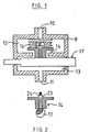
- the preferred regulator shown in the drawings comprises a housing 9 with a fluid inlet 10 and a fluid outlet 11. Between the inlet and outlet are an inlet chamber 12, an outlet chamber 13 and a valve 14 between them which can open and close communication between the chambers. This valve is urged into the closed position by a spring 16. Below the valve is a plunger or cam rod 17, the cross-sectional profile of which can be seen in Figures 2, 4 and 6.
- the central portion 20 of the cam rod comprises an oval cam section while the end portions 21, 22 are cylindrical, but of different diameters.
- the smaller diameter portion at the left of Figure 1 passes through a sealed aperture in the housing.
- the larger diameter portion at the right of Figure 1 also passes through a sealed aperture so that the plunger can move axially with respect to the housing and can also rotate with respect to the housing without allowing fluid to escape passed the seals.
- the cam rod is arranged to move in two different modes.
- the two modes are rotational and axial movements within the chamber 13.
- These movements can be effected by any appropriate operating mechanism such as a solenoid or servo-mechanism arrangement, typically controlled by electronic circuitry such as a micro-processor or other electronic control circuit.
- valve Normally, the valve will be held open as shown in Figures 1 and 2. However, if a wheel of the vehicle locks up under heavy braking, a sensor at the wheel will detect that it is moving more slowly than the other wheels. This will cause the electronic operating circuit to rotate the cam rod 17 into the position shown in Figure 4, so that the valve 14 is closed under the urging of the spring 16, as shown in Figure 3. The valve thereby disrupts communication between the master cylinder (pressure generating mechanism) and the slave cylinder (hydraulic actuating means). No further pressure therefore can be applied to the brake on that wheel, regardless of how much pressure is applied to the rest of the system.
- this is done by moving the cam rod 17 to the right in the arrangement shown in Figure 3. This means that the volume of the chamber 13 is increased as the wider diameter portion 22 enters it. The increase in volume will, of course, reduce the pressure of the brake fluid within the chamber, and also at the slave cylinder.
- valve can be opened again effectively to restore the valve to normal operating conditions.
- a pilot valve e. g. a needle valve 23 is provided within the main valve 14 and this can be opened by further rotation of the cam member 17, as shown in Figures 5 and 6.
- the valve 23 is normally urged to the closed position by a biasing means, such as a spring 24, except when pushed open by the cam 17.
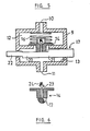
- Figure 7 shows an anti-lock braking system applied to one wheel of a motorcycle having a brake disc 30, a wheel cylinder 31 capable of applying disc brakes, and operated hydraulically from a master cylinder 32 via hydraulic line 33.
- the rotation of the disc 30 is monitored by an inductive wheel sensor 35 which sends an electrical signal to an electronic control unit 36 (e. g. a micro-processor capable of controlling more than one wheel cylinder).
- an electronic control unit 36 e. g. a micro-processor capable of controlling more than one wheel cylinder.
- the pressure regulator 37 is shown schematically in line 33 and its valve can interrupt the application of brake pressure from the master cylinder 32 to the wheel cylinder 31.
- a solenoid 40 is controlled by the unit 36 and can be operated to cause a ferrous core plunger 41 to rotate or reciprocate as described with reference to Figures 1-6.
- the pressure regulator of the preferred embodiment provides a simple and effective means of regulating or modulating the. pressure to the wheel cylinders of a vehicle braking system.
- Such a regulator controlled by a electric solenoid in response to electrical signals from a wheel sensor allows an anti-lock braking system to be installed on small vehicles without the need for pumps or servo-mechanisms to assist with the hydraulic fluid pressure.
- an anti-locking braking system can be installed on motorcycles or small cars using only the hydraulic braking pressure generated by the rider or driver (although the regulator can also be used with servo-assisted brakes).
- a single regulator may serve two or more wheels.
- valve 14 may be biased to its position, it may be biased to its open position, to remain there until a cam or other mechanism pushes it closed.
- the by-pass valve 23 need not necessarily be mounted within the main valve 14, but could be located elsewhere between the chambers 12 and 13.
- the rod 17 which combines the functions of opening and closing the valve and of increasing and decreasing the volume of the chamber 13 could be replaced by two separate members each performing a separate task. In other words, one member would operate the valve, while the other, typically a diaphragm or a piston-and-cylinder arrangement, would control the volume of the chamber.
- the present invention may be provided for use in machinery, other than vehicles, where it may be required to apply braking to more than one part of the machine at a time.
- Any suitable sensing arrangement for detecting the speed of the wheels may be used, and any suitable operating system or electronic or fluidic control circuitry may be used between the sensing device and the regulator.
Landscapes
- Engineering & Computer Science (AREA)
- Physics & Mathematics (AREA)
- Fluid Mechanics (AREA)
- Transportation (AREA)
- Mechanical Engineering (AREA)
- Electromagnetism (AREA)
- Regulating Braking Force (AREA)
Description
- This invention relates to a pressure regulator for braking systems, variously known as anti-locking or anti-skid braking systems.
- In the past, various attempts have been made to provide a regulating mechanism for the hydraulic pressure of a vehicular brake mechanism. The purpose is to decrease the pressure on a hydraulic brake when a sensor detects that the wheel locks up and thus risk skidding on the road surface. Such attempts have generally been made by providing means for pumping fluid away from the operating or slave cylinder of the brake on the locked wheel.
- Examples of prior art anti-locking braking systems include :
- Lester et al US-A-3,544,171
- Skoyles US-A-3,724,914
- Gfeller US-A-3,752,268
- Baynes et al US-A-4,046,427
- Alfred Teves GmbH FR-A-2551007
- FR-A-2551007 discloses the use of a three-dimensional cam whose cross-sectional shape varies along its length. Rotation of the cam causes push rods abutting the surface of the cam to move pistons within hydraulic cylinders thus opening and closing a valve within the cylinder. The periods of time for which pressure is increasing or decreasing within an outlet chamber of the cylinder depends on the part of the cam surface with which the push rods come into contact.
- US-A-3,544,171 discloses the use of a servo controlled piston to move a cylinder into or out of a chamber to vary the chamber volume and hence decrease the braking pressure when skidding occurs.
- US-A-4,046,427 discloses an inertial cam which is responsive to the skidding of a rear wheel, and requires a complex fly-wheel arrangement to regulate the braking pressure.
- US-A-3,724,914 teaches the use of a rotary cam to actuate a pump thereby increasing braking pressure after the brake pressure has been released.
- US-A-3,752,268 describes a complex system for controlling the braking pressure on a mountain railway.
- Such regulators have, however, been expensive to construct and install.
- Their complexity and need for servos on pumps increase the size and weight of the entire braking system.
- It is an object of the present invention to provide a simple pressure regulating means for hydraulic brake mechanisms, or which will at least provide brake manufacturers with a useful choice.
- In a first aspect the invention provides a pressure regulator for an anti-lock hydraulic braking system, the regulator including a housing with an inlet chamber and an outlet chamber ; an inlet for hydraulic fluid to the inlet chamber, an outlet for hydraulic fluid from the outlet chamber and a passage for the hydraulic fluid between the inlet chamber and the outlet chamber ; valve means which can be opened and closed to control the flow of hydraulic fluid through the passage between the inlet chamber and the outlet chamber ; and a plunger locatable in the outlet chamber and capable of being moved therein to vary the volume of the outlet chamber occupied by the hydraulic fluid to modulate the pressure within the outlet chamber when the fluid connection between the inlet and outlet chambers is cut off, characterised in that the plunger is rotatable in the outlet chamber and comprises a cam in contact with the valve means, the cam being arranged upon rotation of the plunger to open and close the valve means.
- In a second aspect the invention provides an anti-lock hydraulic braking system including : at least one pressure regulator as described in the preceding paragraph ; at least one hydraulic actuating means, each arranged to apply a brake to a moving object ; at least one sensor, each sensor at or adjacent each moving object ; a hydraulic pressure generator adapted to supply hydraulic fluid under pressure to said hydraulic actuating means to apply said brakes ; and at least one of said pressure regulators between said pressure generator and said actuating means to regulate the hydraulic fluid pressure reaching the actuating means in response to signals from said sensor (s).
- Preferably, the plunger extends into the outlet chamber and the pressure modulation is effected by varying the volume of the outlet chamber available to the hydraulic fluid by moving the bulk of the plunger into or out of the chamber.
- It is further preferred that the plunger extends through apertures in the housing and the plunger has one region of reduced cross-section and one region of a larger cross-section, so that movement of the plunger in one direction will withdraw a portion of the larger cross-section of the plunger from the outlet chamber whilst allowing a portion of the reduced cross-section of the plunger to enter the outlet chamber whereby the available fluid volume of the outlet chamber is reduced. Preferably, the cam is integral with the plunger. Preferably the valve means comprises two valve members, a first, main, valve member and a second, pilot, valve member each of which can be opened by the cam.
- Preferably, the valve means comprises two valve members, a first, main, valve member normally open but arranged to be closed by the operating means when the sensor causes the operating means to close the valve, and a second pilot valve member normally closed, but arranged to be opened if the sensor indicates that the moving object, once freed from locking, is rotating more freely, so that further pressure can be transmitted to the moving object.
- Preferably the plunger is operated by an electric solenoid receiving an electrical signal from a sensor.
- By using the combined cam/plunger with a solenoid to rotate the plunger and to move the plunger axially the pressure regulator can be a compact unit allowing for a simple and relatively lightweight anti-lock braking system.
- The above gives a broad description of the present invention, a preferred form of which will now be described by way of example with reference to the accompanying drawings in which :
- Figure 1 as a cross-sectional view of a pressure regulator in accordance with the present invention.
- Figure 2 is a sectional view of part of the mechanism shown in Figure 1.
- Figure 3 is a view similar to Figure 1 showing the mechanism in a second configuration.
- Figure 4 is a sectional view of part of the mechanism shown in Figure 3.
- Figure 5 is the mechanism shown in Figures 1 and 3 in a third configuration.
- Figure 6 is a sectional view of part of the mechanism shown in Figure 5.
- Figure 7 is a schematic view of an anti-lock braking system applied to the disc brake of one wheel.
- The preferred regulator shown in the drawings comprises a
housing 9 with afluid inlet 10 and afluid outlet 11. Between the inlet and outlet are aninlet chamber 12, anoutlet chamber 13 and avalve 14 between them which can open and close communication between the chambers. This valve is urged into the closed position by aspring 16. Below the valve is a plunger orcam rod 17, the cross-sectional profile of which can be seen in Figures 2, 4 and 6. The central portion 20 of the cam rod comprises an oval cam section while theend portions 21, 22 are cylindrical, but of different diameters. The smaller diameter portion at the left of Figure 1 passes through a sealed aperture in the housing. The larger diameter portion at the right of Figure 1 also passes through a sealed aperture so that the plunger can move axially with respect to the housing and can also rotate with respect to the housing without allowing fluid to escape passed the seals. - The cam rod is arranged to move in two different modes. In this instance the two modes are rotational and axial movements within the
chamber 13. These movements can be effected by any appropriate operating mechanism such as a solenoid or servo-mechanism arrangement, typically controlled by electronic circuitry such as a micro-processor or other electronic control circuit. - Normally, the valve will be held open as shown in Figures 1 and 2. However, if a wheel of the vehicle locks up under heavy braking, a sensor at the wheel will detect that it is moving more slowly than the other wheels. This will cause the electronic operating circuit to rotate the
cam rod 17 into the position shown in Figure 4, so that thevalve 14 is closed under the urging of thespring 16, as shown in Figure 3. The valve thereby disrupts communication between the master cylinder (pressure generating mechanism) and the slave cylinder (hydraulic actuating means). No further pressure therefore can be applied to the brake on that wheel, regardless of how much pressure is applied to the rest of the system. - If the system is such that the sensor is able to detect a wheel that is just about to lock, such an arrangement may be sufficient for most circumstances. However, it is more likely that it will now be desirable to reduce the pressure to the brake to allow the wheel to start moving again. This is done by increasing the volume of the fluid downstream of the valve.
- In the illustrated embodiment, this is done by moving the
cam rod 17 to the right in the arrangement shown in Figure 3. This means that the volume of thechamber 13 is increased as thewider diameter portion 22 enters it. The increase in volume will, of course, reduce the pressure of the brake fluid within the chamber, and also at the slave cylinder. - Normally, only small movements of the
rod 17 will be required to enable the brake pressure at the slave cylinder to be reduced sufficiently to release the brakes. When this happens, the sensor at the wheel will detect the renewed movement of the wheel, and further movement of therod 17 can then be prevented. If the wheel starts to move a bit too freely, therod 17 can be moved back again under the control of the control circuitry so that the volume within thechamber 13 is reduced again to increase the pressure. This process can be continued back and forth until the pressure is just sufficient to provide the correct amount of braking of the wheel. - If it is required to apply more pressure than can be achieved by longitudinal movement of the rod, the valve can be opened again effectively to restore the valve to normal operating conditions. However, while pressure is still being applied in the
upstream chamber 12, it will be difficult to open thevalve 14 against the pressure. Instead, a pilot valve, e. g. aneedle valve 23, is provided within themain valve 14 and this can be opened by further rotation of thecam member 17, as shown in Figures 5 and 6. Thevalve 23 is normally urged to the closed position by a biasing means, such as aspring 24, except when pushed open by thecam 17. - If the pressure at the brake is sufficient once again to cause the wheel to lock up, further rotation of the
cam member 17 back to the position shown in Figure 3 will once again cut off the further supply of pressure to the brake cylinder, and the pressure can once again be adjusted by longitudinal movement of therod 17. - Figure 7 shows an anti-lock braking system applied to one wheel of a motorcycle having a
brake disc 30, awheel cylinder 31 capable of applying disc brakes, and operated hydraulically from a master cylinder 32 viahydraulic line 33. - The rotation of the
disc 30 is monitored by aninductive wheel sensor 35 which sends an electrical signal to an electronic control unit 36 (e. g. a micro-processor capable of controlling more than one wheel cylinder). - The
pressure regulator 37 is shown schematically inline 33 and its valve can interrupt the application of brake pressure from the master cylinder 32 to thewheel cylinder 31. Asolenoid 40 is controlled by theunit 36 and can be operated to cause aferrous core plunger 41 to rotate or reciprocate as described with reference to Figures 1-6. - Thus, the pressure regulator of the preferred embodiment provides a simple and effective means of regulating or modulating the. pressure to the wheel cylinders of a vehicle braking system.
- By using the combined cam and plunger to vary the volume of the outlet chamber and to control the opening of the valve means between the inlet and outlet chamber it is possible to provide a compact pressure regulator.
- Such a regulator controlled by a electric solenoid in response to electrical signals from a wheel sensor allows an anti-lock braking system to be installed on small vehicles without the need for pumps or servo-mechanisms to assist with the hydraulic fluid pressure.
- Thus an anti-locking braking system can be installed on motorcycles or small cars using only the hydraulic braking pressure generated by the rider or driver (although the regulator can also be used with servo-assisted brakes).
- Many modifications to the above may be made without departing from the scope of the present invention.
- For example, instead of there being a separate regulating mechanism for each wheel of the vehicle, a single regulator may serve two or more wheels.
- Instead of the
valve 14 being spring biased to its closed position, it may be biased to its position, it may be biased to its open position, to remain there until a cam or other mechanism pushes it closed. The by-pass valve 23 need not necessarily be mounted within themain valve 14, but could be located elsewhere between thechambers - The
rod 17 which combines the functions of opening and closing the valve and of increasing and decreasing the volume of thechamber 13 could be replaced by two separate members each performing a separate task. In other words, one member would operate the valve, while the other, typically a diaphragm or a piston-and-cylinder arrangement, would control the volume of the chamber. - The present invention may be provided for use in machinery, other than vehicles, where it may be required to apply braking to more than one part of the machine at a time.
- Any suitable sensing arrangement for detecting the speed of the wheels may be used, and any suitable operating system or electronic or fluidic control circuitry may be used between the sensing device and the regulator.
Claims (7)
Applications Claiming Priority (2)
| Application Number | Priority Date | Filing Date | Title |
|---|---|---|---|
| NZ211548A NZ211548A (en) | 1985-03-22 | 1985-03-22 | Pressure regulator for anti lock hydraulic braking systems |
| NZ211548 | 1985-03-22 |
Publications (2)
| Publication Number | Publication Date |
|---|---|
| EP0200331A1 EP0200331A1 (en) | 1986-11-05 |
| EP0200331B1 true EP0200331B1 (en) | 1988-12-21 |
Family
ID=19921144
Family Applications (1)
| Application Number | Title | Priority Date | Filing Date |
|---|---|---|---|
| EP86302028A Expired EP0200331B1 (en) | 1985-03-22 | 1986-03-19 | Pressure regulator |
Country Status (6)
| Country | Link |
|---|---|
| US (1) | US4695101A (en) |
| EP (1) | EP0200331B1 (en) |
| JP (1) | JPS61241250A (en) |
| AU (1) | AU5474086A (en) |
| DE (1) | DE3661471D1 (en) |
| NZ (1) | NZ211548A (en) |
Families Citing this family (2)
| Publication number | Priority date | Publication date | Assignee | Title |
|---|---|---|---|---|
| AU7563487A (en) * | 1986-07-22 | 1988-01-28 | Dfc New Zealand Ltd. | Anti-skid braking system |
| CN112138363B (en) * | 2020-09-25 | 2022-05-13 | 重庆第二师范学院 | Anti-lock roller skating structure and anti-lock cross-country roller skating shoe |
Family Cites Families (10)
| Publication number | Priority date | Publication date | Assignee | Title |
|---|---|---|---|---|
| US3466098A (en) * | 1968-05-21 | 1969-09-09 | Topia Sa | Anti-lock device for the braked wheels of motor vehicles |
| JPS5528898B2 (en) * | 1972-07-25 | 1980-07-31 | ||
| CH1827672A4 (en) * | 1972-12-15 | 1974-11-29 | ||
| DE2316786A1 (en) * | 1973-04-04 | 1974-10-17 | Daimler Benz Ag | PRESSURE REGULATING DEVICE FOR VEHICLES WITH AN ANTI-LOCKING DEVICE |
| SE392435B (en) * | 1975-02-19 | 1977-03-28 | Blomberg Folke Ivar | LOAD PREVENTION UNIT FOR BUILDING INTO A HYDRAULIC FLUID CIRCUIT |
| US4095851A (en) * | 1975-12-04 | 1978-06-20 | Aisin Seiki Kabushiki Kaisha | Modulator for anti-skid brake control system |
| DE2631346A1 (en) * | 1976-07-13 | 1978-01-19 | Bosch Gmbh Robert | ANTI-SKID DEVICE FOR AIR-ACTUATED BRAKES OF A MOTOR VEHICLE |
| CS192760B1 (en) * | 1977-03-31 | 1979-09-17 | Josef Kovar | Dynamic pressure regulator especially for the antiblocking devices of the vehicles brakes |
| DE3133283A1 (en) * | 1981-08-22 | 1983-03-03 | FAG Kugelfischer Georg Schäfer & Co, 8720 Schweinfurt | Displacement piston unit for antilock hydraulic brake systems |
| DE3330483A1 (en) * | 1983-08-24 | 1985-03-07 | Alfred Teves Gmbh, 6000 Frankfurt | BRAKE SLIP-CONTROLLED BRAKE SYSTEM FOR MOTOR VEHICLES |
-
1985
- 1985-03-22 NZ NZ211548A patent/NZ211548A/en unknown
-
1986
- 1986-03-11 US US06/838,597 patent/US4695101A/en not_active Expired - Fee Related
- 1986-03-14 AU AU54740/86A patent/AU5474086A/en not_active Abandoned
- 1986-03-19 EP EP86302028A patent/EP0200331B1/en not_active Expired
- 1986-03-19 DE DE8686302028T patent/DE3661471D1/en not_active Expired
- 1986-03-20 JP JP61063868A patent/JPS61241250A/en active Pending
Also Published As
| Publication number | Publication date |
|---|---|
| JPS61241250A (en) | 1986-10-27 |
| US4695101A (en) | 1987-09-22 |
| AU5474086A (en) | 1986-09-25 |
| NZ211548A (en) | 1987-03-31 |
| EP0200331A1 (en) | 1986-11-05 |
| DE3661471D1 (en) | 1989-01-26 |
Similar Documents
| Publication | Publication Date | Title |
|---|---|---|
| US4662687A (en) | Anti-skid brake system and anti-drive-slip system | |
| EP0389993B1 (en) | Electronically controlled brake device | |
| EP0297797B1 (en) | An hydraulic anti-skid vehicle braking system | |
| JP3620108B2 (en) | Accumulation control device | |
| GB2134200A (en) | Anti-locking system for a two-wheel road vehicle with hydraulic dual circuit braking installation | |
| US4547022A (en) | Hydraulic anti-skid braking systems for vehicles | |
| US4556260A (en) | Apparatus for preventing the locking of a wheel | |
| CN109733355A (en) | An integrated electronic hydraulic braking system and method | |
| US4552413A (en) | Anti-skid brake control system for automobiles | |
| US4005759A (en) | Solenoid-operated valve | |
| US5029950A (en) | Anti-lock braking and traction control system | |
| US4068904A (en) | Anti-locking brake apparatus and method | |
| US3677608A (en) | Adaptive braking system with hydraulically powered modulator | |
| US4275934A (en) | Anti-lock brake devices | |
| EP0200331B1 (en) | Pressure regulator | |
| EP0227332B1 (en) | Vehicle anti-skid braking systems | |
| US3695732A (en) | Pressure modulating device for use in anti-skid brake system | |
| US3905441A (en) | Method and apparatus for controlling the brakes of vehicles | |
| US5503250A (en) | Traction control system | |
| US4730878A (en) | Skid-controlled hydraulic brake system | |
| US6276765B1 (en) | Integrated anti-skid and hydraulic booster braking control | |
| US3603649A (en) | Hydraulic braking systems for vehicles | |
| US6092881A (en) | Traction control system | |
| JP3867308B2 (en) | Fault detection method for hydraulic control device | |
| EP0507492B1 (en) | Improvement in hydraulic anti-lock braking systems for vehicles |
Legal Events
| Date | Code | Title | Description |
|---|---|---|---|
| PUAI | Public reference made under article 153(3) epc to a published international application that has entered the european phase |
Free format text: ORIGINAL CODE: 0009012 |
|
| AK | Designated contracting states |
Kind code of ref document: A1 Designated state(s): AT BE CH DE FR GB IT LI LU NL SE |
|
| 17P | Request for examination filed |
Effective date: 19870401 |
|
| 17Q | First examination report despatched |
Effective date: 19880317 |
|
| GRAA | (expected) grant |
Free format text: ORIGINAL CODE: 0009210 |
|
| AK | Designated contracting states |
Kind code of ref document: B1 Designated state(s): BE DE FR GB IT SE |
|
| PG25 | Lapsed in a contracting state [announced via postgrant information from national office to epo] |
Ref country code: BE Effective date: 19881221 |
|
| REF | Corresponds to: |
Ref document number: 3661471 Country of ref document: DE Date of ref document: 19890126 |
|
| PGFP | Annual fee paid to national office [announced via postgrant information from national office to epo] |
Ref country code: FR Payment date: 19890316 Year of fee payment: 4 |
|
| PGFP | Annual fee paid to national office [announced via postgrant information from national office to epo] |
Ref country code: DE Payment date: 19890318 Year of fee payment: 4 |
|
| ITF | It: translation for a ep patent filed | ||
| PGFP | Annual fee paid to national office [announced via postgrant information from national office to epo] |
Ref country code: SE Payment date: 19890320 Year of fee payment: 4 |
|
| ET | Fr: translation filed | ||
| PLBE | No opposition filed within time limit |
Free format text: ORIGINAL CODE: 0009261 |
|
| STAA | Information on the status of an ep patent application or granted ep patent |
Free format text: STATUS: NO OPPOSITION FILED WITHIN TIME LIMIT |
|
| 26N | No opposition filed | ||
| PG25 | Lapsed in a contracting state [announced via postgrant information from national office to epo] |
Ref country code: GB Effective date: 19900319 |
|
| PG25 | Lapsed in a contracting state [announced via postgrant information from national office to epo] |
Ref country code: SE Effective date: 19900320 |
|
| ITTA | It: last paid annual fee | ||
| GBPC | Gb: european patent ceased through non-payment of renewal fee | ||
| PG25 | Lapsed in a contracting state [announced via postgrant information from national office to epo] |
Ref country code: FR Effective date: 19901130 |
|
| PG25 | Lapsed in a contracting state [announced via postgrant information from national office to epo] |
Ref country code: DE Effective date: 19901201 |
|
| REG | Reference to a national code |
Ref country code: FR Ref legal event code: ST |
|
| EUG | Se: european patent has lapsed |
Ref document number: 86302028.5 Effective date: 19910110 |
|
| PG25 | Lapsed in a contracting state [announced via postgrant information from national office to epo] |
Ref country code: IT Free format text: LAPSE BECAUSE OF NON-PAYMENT OF DUE FEES;WARNING: LAPSES OF ITALIAN PATENTS WITH EFFECTIVE DATE BEFORE 2007 MAY HAVE OCCURRED AT ANY TIME BEFORE 2007. THE CORRECT EFFECTIVE DATE MAY BE DIFFERENT FROM THE ONE RECORDED. Effective date: 20050319 |