EP0200238B1 - Optical multiplexer device - Google Patents
Optical multiplexer device Download PDFInfo
- Publication number
- EP0200238B1 EP0200238B1 EP86200423A EP86200423A EP0200238B1 EP 0200238 B1 EP0200238 B1 EP 0200238B1 EP 86200423 A EP86200423 A EP 86200423A EP 86200423 A EP86200423 A EP 86200423A EP 0200238 B1 EP0200238 B1 EP 0200238B1
- Authority
- EP
- European Patent Office
- Prior art keywords
- face
- optical
- fibre
- wavelength
- fibres
- Prior art date
- Legal status (The legal status is an assumption and is not a legal conclusion. Google has not performed a legal analysis and makes no representation as to the accuracy of the status listed.)
- Expired
Links
Images


Classifications
-
- G—PHYSICS
- G02—OPTICS
- G02B—OPTICAL ELEMENTS, SYSTEMS OR APPARATUS
- G02B6/00—Light guides; Structural details of arrangements comprising light guides and other optical elements, e.g. couplings
- G02B6/24—Coupling light guides
- G02B6/26—Optical coupling means
- G02B6/28—Optical coupling means having data bus means, i.e. plural waveguides interconnected and providing an inherently bidirectional system by mixing and splitting signals
- G02B6/293—Optical coupling means having data bus means, i.e. plural waveguides interconnected and providing an inherently bidirectional system by mixing and splitting signals with wavelength selective means
- G02B6/29304—Optical coupling means having data bus means, i.e. plural waveguides interconnected and providing an inherently bidirectional system by mixing and splitting signals with wavelength selective means operating by diffraction, e.g. grating
- G02B6/29305—Optical coupling means having data bus means, i.e. plural waveguides interconnected and providing an inherently bidirectional system by mixing and splitting signals with wavelength selective means operating by diffraction, e.g. grating as bulk element, i.e. free space arrangement external to a light guide
- G02B6/2931—Diffractive element operating in reflection
-
- G—PHYSICS
- G02—OPTICS
- G02B—OPTICAL ELEMENTS, SYSTEMS OR APPARATUS
- G02B6/00—Light guides; Structural details of arrangements comprising light guides and other optical elements, e.g. couplings
- G02B6/24—Coupling light guides
- G02B6/26—Optical coupling means
- G02B6/28—Optical coupling means having data bus means, i.e. plural waveguides interconnected and providing an inherently bidirectional system by mixing and splitting signals
- G02B6/293—Optical coupling means having data bus means, i.e. plural waveguides interconnected and providing an inherently bidirectional system by mixing and splitting signals with wavelength selective means
- G02B6/29379—Optical coupling means having data bus means, i.e. plural waveguides interconnected and providing an inherently bidirectional system by mixing and splitting signals with wavelength selective means characterised by the function or use of the complete device
- G02B6/2938—Optical coupling means having data bus means, i.e. plural waveguides interconnected and providing an inherently bidirectional system by mixing and splitting signals with wavelength selective means characterised by the function or use of the complete device for multiplexing or demultiplexing, i.e. combining or separating wavelengths, e.g. 1xN, NxM
-
- G—PHYSICS
- G02—OPTICS
- G02B—OPTICAL ELEMENTS, SYSTEMS OR APPARATUS
- G02B6/00—Light guides; Structural details of arrangements comprising light guides and other optical elements, e.g. couplings
- G02B6/24—Coupling light guides
- G02B6/26—Optical coupling means
- G02B6/28—Optical coupling means having data bus means, i.e. plural waveguides interconnected and providing an inherently bidirectional system by mixing and splitting signals
- G02B6/293—Optical coupling means having data bus means, i.e. plural waveguides interconnected and providing an inherently bidirectional system by mixing and splitting signals with wavelength selective means
- G02B6/29379—Optical coupling means having data bus means, i.e. plural waveguides interconnected and providing an inherently bidirectional system by mixing and splitting signals with wavelength selective means characterised by the function or use of the complete device
- G02B6/29395—Optical coupling means having data bus means, i.e. plural waveguides interconnected and providing an inherently bidirectional system by mixing and splitting signals with wavelength selective means characterised by the function or use of the complete device configurable, e.g. tunable or reconfigurable
Definitions
- the invention relates to an optical multiplexer device which includes a plurality of optical fibres, one end face of each optical fibre being arranged in a common plane, which plurality includes a first optical fibre for conducting several light signals of different wavelength and at least two second optical fibres, each of which serves to conduct a light signal in a given waveband, a wavelength-selective element and a lens system which is arranged between the wavelength-selective element on the one side and the common plane on the other side, the arrangement being such that a low-attenuation transmission path which is dependent of the wavelength of the light is formed between the first optical fibre and each of the second optical fibres.
- the optical multiplexer device may be a multiplexer as well as a demultiplexer.
- the second optical fibres serve for the input signals whilst the first optical fibre serves for the output signal.
- the first optical fibre constitutes the input fibre whilst the second optical fibres constitute output fibres.
- a device of the kind set forth is known from EP-A 74152).
- the construction of the known device is comparatively complex; this is inter aria due to the fact that therein the orientation of the wavelength-selective element with respect to the incident light beam is adjustable. In many cases, however, it is sufficient to adjust the device properly during assembly; adjustability during operation is then no longer necessary. In such cases it is notably important that the cost price of the device is as low as possible.
- the device in accordance with the invention is characterized in that the lens system includes a plane parallel, transparent plate, a first main surface of which is arranged against the end faces of the optical fibres arranged in the common plane, and also includes a piano-spherical lens whose plane surface is arranged against the second main surface.
- the thickness of the transparent plate determines the distance between the lens and the end faces of the fibres. This thickness can be preselected so that the focal point of the lens is situated in the common plane and the focal distance of the lens need not be adjusted.
- the direction of the light beams emerging from the lens can be simply adjusted during assembly by displacing the lens across the plate. When the correct position is reached, the lens can be secured in that position by means of a suitable adhesive.
- the device in accordance with the invention it is particularly simple to secure the transparent plate against the end faces of the fibres and to mount the wavelength-selective element, because the common plane in which the end faces of the optical fibres are situated coincides with an end face of a fibre holder in which the end portions of the fibres are retained, the first main surface of the transparent plate bearing against said end face, the lens system being accommodated in a wedge-shaped space which is recessed in a housing and which is bounded by a first wedge face which extends parallel to said end face of the fibre holder and by a second wedge face where against the wavelength-selective element is arranged.
- Figure 1 shows a multiplexer device which includes a plurality of optical fibres which are adjacently arranged so as to form a ribbon 1.
- the protective sheath of the fibres has been removed, so that the width at this end is smaller than that of the remainder of the ribbon.
- the end portions of the fibres are retained in a fibre holder 5 having an end face 7 which coincides with a common plane in which the end faces of the optical fibres are situated.
- Figure 2 shows a part of the end face 7, together with the end faces 9, 11 of the optical fibres 13, 15.
- the optical fibres include a first fibre 13 for conducting various light signals of different wavelength, and four second optical fibres 15, each of which serves to conduct a light signal in a given waveband.
- the fibre holder 5 of the embodiment shown consists of two portions 17 and 19, each of which has a mainly plane side 21, 23, respectively, said sides being arranged one against the other.
- a step 25 and 27 respectively, so that between the portions 17 and 19 there is formed a rectangular space 29 in which the end portions of the optical fibres 13, 15 are retained.
- the end portions of all optical fibres 13, 15 have the same diameter and the two portions 17, 19 of the fibre holder 5 are arranged one against the other in such a manner that the width of the rectangular space 29 is equal to this diameter and its length is equal to the diameter multiplied by the number of fibres, so in this embodiment it equals five times the diameter.
- the space 29 is filled with an adhesive which has not yet set, for example an epoxy glue.
- an adhesive which has not yet set, for example an epoxy glue.
- the two portions 17, 19 and the fibres 13, 15 form a rigid assembly which can be polished so that the end faces 9, 11 and the end face 7 are situated in a common plane.
- the ribbon 1 formed by the further portions of the optical fibres can be secured to the fibre holder 5 by means of a further glued joint 31 (see Figure 1).
- a wavelength-selective element 33 in the form of a reflection grating.
- the wavelength-selective element is secured on a wedge-shaped housing 35.
- the housing 35 includes two wedge faces, the first wedge face 37 bearing against the holder 5 whilst the wavelength-selective element 33 is secured against the second wedge face 39, for example by means of a suitable glue such as a cyano-acrylate glue.
- the first wedge face 37 bears on an edge 41 which is formed on the fibre holder 5 and which encloses the end face 7, so that the first wedge face extends parallel to the end face.
- the angle enclosed by the two wedge faces 37, 39 determines the angle between the axes of the optical fibres 13, 15 on the one side and the plane of the grating 33 on the other side.
- FIG 3 is a plan view at a reduced scale of the housing 35.
- the housing includes an annular base portion 43 which is provided with a central aperture 44 for accommodating the end face 7.
- In the base portion there are formed two semicircular recesses 45 which adjoin the central aperture 44 and which serve to accommodate screws (not shown) for securing the housing 35 to the fibre holder 5.
- Some clearance exists between the screws and the recesses 45 so that, prior to the tightening of the screws, the housing can still be shifted slightly for exact adjustment of the grating 33 with respect to the end faces 9, 11 of the fibres 13, 15.
- On both sides of the central aperture 44 there are provided two ridges 47, the upper faces of which define the second wedge face 39.
- a wedge-shaped space 49 which is bounded by the two wedge faces 37, 39 (see Figure 1) and which accommodates a lens system which includes a plane parallel transparent plate 51 (for example, a glass plate) on which a plano-spherical lens 53 (for example, a sapphire lens) is secured.
- a first main surface 55 of the plate 51 bears against the end face 7 of the fibre holder 5 and against the end faces 9, 11 of the optical fibres 13, 15 which are flush with this end face.
- the plate 51 is secured to the fibre holder 5 by means of a suitable glue (for example, Norland UV setting lens cement).
- the glued joint is denoted by the reference numeral 57 in Figure 1.
- the flat surface 59 of the lens 53 bears against the second main surface 61 of the plate 51 and is secured to the plate by means of a glued joint 63 which may be made of the same type of glue as used for the joint 57.
- the lens 53 is displaced across the plate 51 until it reaches the correct position.
- Figures 4A and B These Figures diagrammatically show one of the two optical fibres 15 and the plate 51 and the lens 53.
- the thickness of the plate 51 has been chosen so that the focal plane of the lens 53 coincides with the first main surface 55 of the plate. Because the end face 11 of the fibre 15 bears against this first main surface, the light emerging from this end face is shaped into a parallel light beam 65 by the lens 53.
- the centre of the lens 53 is denoted by the reference numeral 67 in the Figures 4A and B.
- the beam 65 encloses an angle with respect to the normal to the plate 51 (see Figure 4A).
- this angle changes and when the centre 67 is situated on the prolongation of the axis of the optical fibre 15, this angle equals zero, which means that the beam 65 is directed perpendicularly to the plate 51.
- the angle at which light is reflected by a grating depends not only on the properties of the grating and the wavelength of the light, but also on the angle of incidence of the light on the grating. Because this angle of incidence can be simply changed in the described manner, the multiplexer device can be so adjusted by shifting the lens 53 that light of a given wavelength (or in a given narrow waveband) from one of the second optical fibres 15 is reflected to the first optical fibre 13 by the grating 33. Because the second optical fibres 15 are adjacently arranged, the distance between the centre 67 of the lens 53 and the prolongation of the axis of each fibre will differ.
- the light reflected from each of these fibres to the first optical fibre 13 will form part of a different waveband.
- a low-attenuation transmission path which depends on the wavelength of the light is thus formed between each of the second optical fibres 15 on the one side and the first optical fibre 13 on the other side. Because the path of the light rays is reversible, these wavelength-dependent paths also exist in the reverse direction, so that the device can be used not only as a muliplexer but also as a demultiplexer.
- the lens 53 can be displaced across the plate 51 for as long as the glue forming the glued joints 63 (see Figure 1) has not yet set. Once the lens 53 reaches the desired position, the glue is exposed to ultraviolet light, after which the lens will be rigidly secured to the plate 51.
- the wavebands conducted by the various optical fibres are thus defined.
- the multiplexer device shown in Figure 5 includes a cable 101 in which a number of optical fibres are arranged in a rather arbitrary manner.
- the protective envelope has been removed from the free end portions of the fibres which are arranged so as to form a ribbon 103 which is retained in a fibre holder which consists of an inner portion 105 and an outer portion 106.
- the inner portion 105 itself consists of two portions wherebetween the fibres in the form of a ribbon are retained in the same ways as between the two portions 17, 19 of the fibre holder 5 (see Figures 1 and 2).
- the inner portion is secured in the outer portion 106 which will now be described in detail with reference to the Figures 6 and 7.
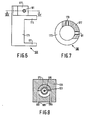
- Figure 6 is a side elevation of the outer portion 106 (viewed from the left in Figure 5) and Figure 7 is a cross-sectional taken along the line VII-VII in Figure 6.
- the outer portion 106 includes a lower ring 171 and an upper ring 173 which are interconnected by means of an approximately semi-cylindrical intermediate portion 175.
- the inner portion is guided from below through the apertures in the rings 171, 173 of the outer portion 106 until its end face 107, in which the end faces of the optical fibres are also situated, coincides with the upper face of the upper ring 173.
- the upper end portion of the inner portion is constructed so as to be conical so that a clearance remains between this end portion and the upper ring 173; this clearance can be filled with a suitable glue 183 for interconnection of the two portions of the fibre holder.
- a plane parallel, transparent plate 151 On the end face 107 there is provided a plane parallel, transparent plate 151, the first main surface 155 of which is arranged against the end face.
- the flat surface 159 of a piano-spherical lens 153 a piano-spherical lens 153.
- the fibre holder 105, 106 is accommodated in a central cavity 185 which is recessed in a housing 135 and which extends from a lower end face 187 of the housing as far as a space 149 which is also recessed in the housing and which is bounded at the lower side by a first wedge face 137 which extends parallel to the end face 107 and which coincides therewith in the present example.
- the wedge-shaped space 149 is bounded at the upper side by a second wedge face 139 whereagainst there is arranged a wavelength-selective element 133 in the form of a reflection grating.
- Figure 8 is a cross-sectional view of the housing 135, taken along the line VIII-VIII in Figure 5, and also shows the cable 101, the inner portion 105 of the fibre holder and the intermediate portion 175 of the outer portion of the fibre holder. Also visible are two adjusting screws 189 which have been screwed into the housing 135 and whose ends bear against the intermediate portion 175 at diametrically situated points. By screwing one adjusting screw 189 further into the housing and by screwing the other adjusting screw further out, the fibre holder 105, 106 can be rotated about its longitudinal axis in order to shift the plane of the ribbon 103 to the desired position with respect to the grating 133. If desired, the fibre holder 105, 106 can subsequently be secured in the housing 135 by means of a suitable glue (not shown), after which the adjusting screws 189 can be removed.
- a suitable glue not shown
- the lens system 151, 153 which is partly enclosed by the adjusting device 177 is situated in the wedge-shaped space 149.
- Adjusting screws (not shown) can be screwed into both threaded apertures 179, 181 (see Figure 7), the ends of said screws then pressing against the lens 153 in two mutually perpendicular directions.
- the adjusting screws are accessible from the outside via apertures 191 in the housing 135, one of said apertures being visible in Figure 5.
- the lens 153 can be positioned exactly over the plane of the ribbon 103, so that the attenuation of the light can be minimized.
- the centre of the lens 153 can be shifted with respect to the axes of the individual fibres of the ribbon 103 in the manner described with reference to the Figures 4A and B.
- the lens 153 can again be secured on the plate 151 by means of a glue 163 which is made to set after completion of the described adjusting operations. If desired, the adjusting screws may subsequently be removed again.
Description
- The invention relates to an optical multiplexer device which includes a plurality of optical fibres, one end face of each optical fibre being arranged in a common plane, which plurality includes a first optical fibre for conducting several light signals of different wavelength and at least two second optical fibres, each of which serves to conduct a light signal in a given waveband, a wavelength-selective element and a lens system which is arranged between the wavelength-selective element on the one side and the common plane on the other side, the arrangement being such that a low-attenuation transmission path which is dependent of the wavelength of the light is formed between the first optical fibre and each of the second optical fibres. The optical multiplexer device may be a multiplexer as well as a demultiplexer. In the former case, the second optical fibres serve for the input signals whilst the first optical fibre serves for the output signal. In the latter case the first optical fibre constitutes the input fibre whilst the second optical fibres constitute output fibres. A device of the kind set forth is known from EP-A 74152).
- The construction of the known device is comparatively complex; this is inter aria due to the fact that therein the orientation of the wavelength-selective element with respect to the incident light beam is adjustable. In many cases, however, it is sufficient to adjust the device properly during assembly; adjustability during operation is then no longer necessary. In such cases it is notably important that the cost price of the device is as low as possible.
- Therefore, it is an object of the invention to provide a device of the kind set forth which can be constructed while using only a very small number of components and which can be comparatively simply adjusted during assembly. To achieve this, the device in accordance with the invention is characterized in that the lens system includes a plane parallel, transparent plate, a first main surface of which is arranged against the end faces of the optical fibres arranged in the common plane, and also includes a piano-spherical lens whose plane surface is arranged against the second main surface.
- The thickness of the transparent plate determines the distance between the lens and the end faces of the fibres. This thickness can be preselected so that the focal point of the lens is situated in the common plane and the focal distance of the lens need not be adjusted. The direction of the light beams emerging from the lens can be simply adjusted during assembly by displacing the lens across the plate. When the correct position is reached, the lens can be secured in that position by means of a suitable adhesive.
- ln a preferred embodiment of the device in accordance with the invention, it is particularly simple to secure the transparent plate against the end faces of the fibres and to mount the wavelength-selective element, because the common plane in which the end faces of the optical fibres are situated coincides with an end face of a fibre holder in which the end portions of the fibres are retained, the first main surface of the transparent plate bearing against said end face, the lens system being accommodated in a wedge-shaped space which is recessed in a housing and which is bounded by a first wedge face which extends parallel to said end face of the fibre holder and by a second wedge face where against the wavelength-selective element is arranged.
- The invention will be described in detail hereinafter with reference to the drawing. Therein:
- Figure 1 is a longitudinal sectional view of a first embodiment of a multiplexer device,
- Figure 2 is a plan view at an increased scale of a detail of the device shown in Figurel,
- Figure 3 is a plan view at a reduced scale of another detail of the device shown in Figure 1,
- Figures 4A and 4B illustrate the path of the light rays during the adjustment of the lens system of the device shown in Figure 1,
- Figure 5 is a longitudinal sectional view of a second embodiment of a multiplexer device,
- Figure 6 is a side elevation of a detail of the device shown in Figure 5,
- Figure 7 is a cross-sectional view of the detail shown in Figure 6, and
- Figure 8 is a cross-sectional view at a reduced scale of the device shown in Figure 5.
- Figure 1 shows a multiplexer device which includes a plurality of optical fibres which are adjacently arranged so as to form a ribbon 1. At the end 3 of the ribbon the protective sheath of the fibres has been removed, so that the width at this end is smaller than that of the remainder of the ribbon. The end portions of the fibres are retained in a
fibre holder 5 having anend face 7 which coincides with a common plane in which the end faces of the optical fibres are situated. Figure 2 shows a part of theend face 7, together with the end faces 9, 11 of theoptical fibres first fibre 13 for conducting various light signals of different wavelength, and four secondoptical fibres 15, each of which serves to conduct a light signal in a given waveband. - The
fibre holder 5 of the embodiment shown consists of twoportions plane side side step 25 and 27, respectively, so that between theportions rectangular space 29 in which the end portions of theoptical fibres optical fibres portions fibre holder 5 are arranged one against the other in such a manner that the width of therectangular space 29 is equal to this diameter and its length is equal to the diameter multiplied by the number of fibres, so in this embodiment it equals five times the diameter. During the clamping of the end portions of thefibres space 29 is filled with an adhesive which has not yet set, for example an epoxy glue. After the setting of the adhesive the twoportions fibres end face 7 are situated in a common plane. For strain-relief of the glued joint thus formed, the ribbon 1 formed by the further portions of the optical fibres can be secured to thefibre holder 5 by means of a further glued joint 31 (see Figure 1). - Opposite the
end face 7 of thefibre holder 5 there is arranged a wavelength-selective element 33 in the form of a reflection grating. The wavelength-selective element is secured on a wedge-shaped housing 35. Thehousing 35 includes two wedge faces, thefirst wedge face 37 bearing against theholder 5 whilst the wavelength-selective element 33 is secured against thesecond wedge face 39, for example by means of a suitable glue such as a cyano-acrylate glue. Thefirst wedge face 37 bears on anedge 41 which is formed on thefibre holder 5 and which encloses theend face 7, so that the first wedge face extends parallel to the end face. The angle enclosed by the two wedge faces 37, 39 (the wedge angle) then determines the angle between the axes of theoptical fibres grating 33 on the other side. - Figure 3 is a plan view at a reduced scale of the
housing 35. The housing includes anannular base portion 43 which is provided with acentral aperture 44 for accommodating theend face 7. In the base portion there are formed twosemicircular recesses 45 which adjoin thecentral aperture 44 and which serve to accommodate screws (not shown) for securing thehousing 35 to thefibre holder 5. Some clearance exists between the screws and therecesses 45 so that, prior to the tightening of the screws, the housing can still be shifted slightly for exact adjustment of thegrating 33 with respect to the end faces 9, 11 of thefibres central aperture 44 there are provided tworidges 47, the upper faces of which define thesecond wedge face 39. - Between the two
ridges 47 there is formed a wedge-shaped space 49 which is bounded by the two wedge faces 37, 39 (see Figure 1) and which accommodates a lens system which includes a plane parallel transparent plate 51 (for example, a glass plate) on which a plano-spherical lens 53 (for example, a sapphire lens) is secured. A firstmain surface 55 of theplate 51 bears against theend face 7 of thefibre holder 5 and against the end faces 9, 11 of theoptical fibres plate 51 is secured to thefibre holder 5 by means of a suitable glue (for example, Norland UV setting lens cement). The glued joint is denoted by the reference numeral 57 in Figure 1. Theflat surface 59 of thelens 53 bears against the secondmain surface 61 of theplate 51 and is secured to the plate by means of a glued joint 63 which may be made of the same type of glue as used for the joint 57. - Before the setting of the glue of the glued joint 63 by irradiation by ultraviolet light, the
lens 53 is displaced across theplate 51 until it reaches the correct position. This is illustrated in the Figures 4A and B. These Figures diagrammatically show one of the twooptical fibres 15 and theplate 51 and thelens 53. The thickness of theplate 51 has been chosen so that the focal plane of thelens 53 coincides with the firstmain surface 55 of the plate. Because theend face 11 of thefibre 15 bears against this first main surface, the light emerging from this end face is shaped into aparallel light beam 65 by thelens 53. The centre of thelens 53 is denoted by thereference numeral 67 in the Figures 4A and B. When this centre is not situated on the prolongation of the axis of thefibre 15, thebeam 65 encloses an angle with respect to the normal to the plate 51 (see Figure 4A). When thelens 53 is displaced across the secondmain surface 61 of theplate 51, this angle changes and when thecentre 67 is situated on the prolongation of the axis of theoptical fibre 15, this angle equals zero, which means that thebeam 65 is directed perpendicularly to theplate 51. As is known (for example, see Applied Optics, 16, No. 8, pp 2180-2194, notably the section "Blazed Gratings" on pages 2184 and 2185), the angle at which light is reflected by a grating depends not only on the properties of the grating and the wavelength of the light, but also on the angle of incidence of the light on the grating. Because this angle of incidence can be simply changed in the described manner, the multiplexer device can be so adjusted by shifting thelens 53 that light of a given wavelength (or in a given narrow waveband) from one of the secondoptical fibres 15 is reflected to the firstoptical fibre 13 by thegrating 33. Because the secondoptical fibres 15 are adjacently arranged, the distance between thecentre 67 of thelens 53 and the prolongation of the axis of each fibre will differ. Consequently the light reflected from each of these fibres to the firstoptical fibre 13 will form part of a different waveband. A low-attenuation transmission path which depends on the wavelength of the light is thus formed between each of the secondoptical fibres 15 on the one side and the firstoptical fibre 13 on the other side. Because the path of the light rays is reversible, these wavelength-dependent paths also exist in the reverse direction, so that the device can be used not only as a muliplexer but also as a demultiplexer. Thelens 53 can be displaced across theplate 51 for as long as the glue forming the glued joints 63 (see Figure 1) has not yet set. Once thelens 53 reaches the desired position, the glue is exposed to ultraviolet light, after which the lens will be rigidly secured to theplate 51. The wavebands conducted by the various optical fibres are thus defined. - The multiplexer device shown in Figure 5 includes a
cable 101 in which a number of optical fibres are arranged in a rather arbitrary manner. The protective envelope has been removed from the free end portions of the fibres which are arranged so as to form aribbon 103 which is retained in a fibre holder which consists of aninner portion 105 and anouter portion 106. Theinner portion 105 itself consists of two portions wherebetween the fibres in the form of a ribbon are retained in the same ways as between the twoportions outer portion 106 which will now be described in detail with reference to the Figures 6 and 7. Figure 6 is a side elevation of the outer portion 106 (viewed from the left in Figure 5) and Figure 7 is a cross-sectional taken along the line VII-VII in Figure 6. Theouter portion 106 includes alower ring 171 and anupper ring 173 which are interconnected by means of an approximately semi-cylindricalintermediate portion 175. On theupper ring 173 there is arranged anadjusting device 177 in the form of a portion of a cylindrical envelope provided with two threadedapertures - After the
fibre ribbon 103 has been glued into theinner portion 105 of the fibre holder in the manner described with reference to Figure 2 and thecable 101 has also been connected to the inner portion by means of a further glued joint 131, the inner portion is guided from below through the apertures in therings outer portion 106 until itsend face 107, in which the end faces of the optical fibres are also situated, coincides with the upper face of theupper ring 173. In order to facilitate the introduction of theinner portion 105 into therings upper ring 173; this clearance can be filled with asuitable glue 183 for interconnection of the two portions of the fibre holder. - On the
end face 107 there is provided a plane parallel,transparent plate 151, the firstmain surface 155 of which is arranged against the end face. Against the secondmain surface 161 of theplate 151 there is arranged theflat surface 159 of a piano-spherical lens 153. The lens system thus formed corresponds to the lens system described with reference to Figure 1. - The
fibre holder central cavity 185 which is recessed in ahousing 135 and which extends from alower end face 187 of the housing as far as aspace 149 which is also recessed in the housing and which is bounded at the lower side by afirst wedge face 137 which extends parallel to theend face 107 and which coincides therewith in the present example. The wedge-shapedspace 149 is bounded at the upper side by asecond wedge face 139 whereagainst there is arranged a wavelength-selective element 133 in the form of a reflection grating. - Figure 8 is a cross-sectional view of the
housing 135, taken along the line VIII-VIII in Figure 5, and also shows thecable 101, theinner portion 105 of the fibre holder and theintermediate portion 175 of the outer portion of the fibre holder. Also visible are two adjustingscrews 189 which have been screwed into thehousing 135 and whose ends bear against theintermediate portion 175 at diametrically situated points. By screwing one adjustingscrew 189 further into the housing and by screwing the other adjusting screw further out, thefibre holder ribbon 103 to the desired position with respect to thegrating 133. If desired, thefibre holder housing 135 by means of a suitable glue (not shown), after which the adjusting screws 189 can be removed. - As appears from Figure 5, the
lens system device 177 is situated in the wedge-shapedspace 149. Adjusting screws (not shown) can be screwed into both threadedapertures 179, 181 (see Figure 7), the ends of said screws then pressing against thelens 153 in two mutually perpendicular directions. The adjusting screws are accessible from the outside viaapertures 191 in thehousing 135, one of said apertures being visible in Figure 5. Using the adjusting screw screwed into theaperture 179, thelens 153 can be positioned exactly over the plane of theribbon 103, so that the attenuation of the light can be minimized. Using the adjusting screws screwed into theaperture 181, the centre of thelens 153 can be shifted with respect to the axes of the individual fibres of theribbon 103 in the manner described with reference to the Figures 4A and B. Thelens 153 can again be secured on theplate 151 by means of aglue 163 which is made to set after completion of the described adjusting operations. If desired, the adjusting screws may subsequently be removed again.
Claims (3)
Applications Claiming Priority (2)
| Application Number | Priority Date | Filing Date | Title |
|---|---|---|---|
| NL8500806A NL8500806A (en) | 1985-03-20 | 1985-03-20 | OPTICAL MULTIPLEX DEVICE. |
| NL8500806 | 1985-03-20 |
Publications (2)
| Publication Number | Publication Date |
|---|---|
| EP0200238A1 EP0200238A1 (en) | 1986-11-05 |
| EP0200238B1 true EP0200238B1 (en) | 1989-07-12 |
Family
ID=19845711
Family Applications (1)
| Application Number | Title | Priority Date | Filing Date |
|---|---|---|---|
| EP86200423A Expired EP0200238B1 (en) | 1985-03-20 | 1986-03-18 | Optical multiplexer device |
Country Status (6)
| Country | Link |
|---|---|
| US (1) | US4718056A (en) |
| EP (1) | EP0200238B1 (en) |
| JP (1) | JPS61219909A (en) |
| CA (1) | CA1261079A (en) |
| DE (1) | DE3664387D1 (en) |
| NL (1) | NL8500806A (en) |
Families Citing this family (12)
| Publication number | Priority date | Publication date | Assignee | Title |
|---|---|---|---|---|
| NL8104121A (en) * | 1981-09-07 | 1983-04-05 | Philips Nv | TUNABLE OPTICAL DEMULTIPLEX DEVICE. |
| US5359685A (en) * | 1991-06-21 | 1994-10-25 | The United States Of America As Represented By The Department Of Health And Human Services | Focusing tips for optical fibers |
| US6038079A (en) * | 1997-10-09 | 2000-03-14 | Imagyn Medical Technologies, Inc. | Sapphire objective system |
| US6570652B1 (en) | 2000-06-02 | 2003-05-27 | Digital Lightwave, Inc. | Athermalization and pressure desensitization of diffraction grating based spectrometer devices |
| US6556297B1 (en) | 2000-06-02 | 2003-04-29 | Digital Lightwave, Inc. | Athermalization and pressure desensitization of diffraction grating based spectrometer devices |
| US6731838B1 (en) | 2000-06-02 | 2004-05-04 | Confluent Photonics Corporation | Athermalization and pressure desensitization of diffraction grating based WDM devices |
| US6741408B2 (en) * | 2000-06-15 | 2004-05-25 | Confluent Photonics Corporation | Thermally stable mounting for a diffraction grating device |
| US7003187B2 (en) | 2000-08-07 | 2006-02-21 | Rosemount Inc. | Optical switch with moveable holographic optical element |
| US6810176B2 (en) | 2000-08-07 | 2004-10-26 | Rosemount Inc. | Integrated transparent substrate and diffractive optical element |
| US6421479B1 (en) | 2000-10-31 | 2002-07-16 | Zolo Technologies, Inc. | Apparatus and method facilitating optical alignment of a bulk optical multiplexer/demultiplexer |
| US6987901B2 (en) * | 2002-03-01 | 2006-01-17 | Rosemount, Inc. | Optical switch with 3D waveguides |
| US9350454B2 (en) * | 2011-01-21 | 2016-05-24 | Finisar Corporation | Multi-laser transmitter optical subassembly |
Family Cites Families (5)
| Publication number | Priority date | Publication date | Assignee | Title |
|---|---|---|---|---|
| DE3134250A1 (en) * | 1981-08-29 | 1983-03-17 | Philips Kommunikations Industrie AG, 8500 Nürnberg | METHOD FOR THE MULTIPLE USE OF FIBER OPTICAL CORDS IN THE WAVELENGTH MULTIPLEX |
| NL8104121A (en) * | 1981-09-07 | 1983-04-05 | Philips Nv | TUNABLE OPTICAL DEMULTIPLEX DEVICE. |
| DE3316511A1 (en) * | 1982-10-23 | 1984-11-08 | Licentia Patent-Verwaltungs-Gmbh, 6000 Frankfurt | Optical wavelength-division multiplexer |
| DE3314820A1 (en) * | 1983-04-23 | 1984-10-25 | Licentia Patent-Verwaltungs-Gmbh, 6000 Frankfurt | OPTICAL MULTIPLEXER OR DEMULTIPLEXER |
| GB8333054D0 (en) * | 1983-12-12 | 1984-01-18 | British Telecomm | Optical wavelength selector |
-
1985
- 1985-03-20 NL NL8500806A patent/NL8500806A/en not_active Application Discontinuation
-
1986
- 1986-03-17 CA CA000504281A patent/CA1261079A/en not_active Expired
- 1986-03-18 US US06/841,133 patent/US4718056A/en not_active Expired - Fee Related
- 1986-03-18 DE DE8686200423T patent/DE3664387D1/en not_active Expired
- 1986-03-18 EP EP86200423A patent/EP0200238B1/en not_active Expired
- 1986-03-19 JP JP61061965A patent/JPS61219909A/en active Pending
Also Published As
| Publication number | Publication date |
|---|---|
| JPS61219909A (en) | 1986-09-30 |
| EP0200238A1 (en) | 1986-11-05 |
| NL8500806A (en) | 1986-10-16 |
| CA1261079A (en) | 1989-09-26 |
| US4718056A (en) | 1988-01-05 |
| DE3664387D1 (en) | 1989-08-17 |
Similar Documents
| Publication | Publication Date | Title |
|---|---|---|
| US4707056A (en) | Optical arrangement having a concave mirror or concave grating | |
| US4208094A (en) | Optical switch | |
| US5493393A (en) | Planar waveguide spectrograph | |
| US6108471A (en) | Compact double-pass wavelength multiplexer-demultiplexer having an increased number of channels | |
| US4335933A (en) | Fiber optic wavelength demultiplexer | |
| EP0200238B1 (en) | Optical multiplexer device | |
| US6498876B1 (en) | Multi-port fiber optic device with v-groove ferrule | |
| US6084695A (en) | Optical fiber wavelength multiplexer and demutiplexer | |
| US5377286A (en) | Optical fiber array and method of making the same | |
| CA1193770A (en) | Adjustable optical demultiplexer | |
| EP0738909B1 (en) | Optical coupler with optical fibre ferrules | |
| US4279464A (en) | Integrated optical wavelength demultiplexer | |
| US20040033528A1 (en) | Dynamic optical devices | |
| US4739501A (en) | Optical multiplexer/demultiplexer | |
| RU2000118775A (en) | INTEGRAL BIDIRECTIONAL MULTIPLEXOR WAVE LENGTHS WITH AXIAL GRADIENT REFRACTION INDICATOR / DIFFRACTION GRILLE | |
| US6246812B1 (en) | V-groove dual fiber collimator for DWDM multiplexor/demultiplexor | |
| JPS60101508A (en) | Light wavelength multiplexer and demultiplexer for bidirectional | |
| US20040067014A1 (en) | Miniature optical multiplexer/de-multiplexer DWDM device, and method of aligning components thereof | |
| JPS6161107A (en) | Optical multiplex separation transmitter | |
| US6983090B2 (en) | High resolution tunable optical filter | |
| EP0563314A4 (en) | ||
| US6493487B1 (en) | Optical waveguide transmission devices | |
| US6504632B1 (en) | Optical transmitter and receiver module which demultiplexes a superimposed optical signal | |
| US7266270B2 (en) | Waveguide to waveguide monitor | |
| JPH0814647B2 (en) | Optical demultiplexer |
Legal Events
| Date | Code | Title | Description |
|---|---|---|---|
| PUAI | Public reference made under article 153(3) epc to a published international application that has entered the european phase |
Free format text: ORIGINAL CODE: 0009012 |
|
| AK | Designated contracting states |
Kind code of ref document: A1 Designated state(s): DE FR GB IT SE |
|
| PUAB | Information related to the publication of an a document modified or deleted |
Free format text: ORIGINAL CODE: 0009199EPPU |
|
| PUAF | Information related to the publication of a search report (a3 document) modified or deleted |
Free format text: ORIGINAL CODE: 0009199SEPU |
|
| R17D | Deferred search report published (corrected) |
Effective date: 19861210 |
|
| RA1 | Application published (corrected) |
Date of ref document: 19861210 Kind code of ref document: A1 |
|
| 17P | Request for examination filed |
Effective date: 19870313 |
|
| 17Q | First examination report despatched |
Effective date: 19880810 |
|
| RAP1 | Party data changed (applicant data changed or rights of an application transferred) |
Owner name: NKF KABEL B.V. |
|
| GRAA | (expected) grant |
Free format text: ORIGINAL CODE: 0009210 |
|
| AK | Designated contracting states |
Kind code of ref document: B1 Designated state(s): DE FR GB IT SE |
|
| ITF | It: translation for a ep patent filed |
Owner name: JACOBACCI & PERANI S.P.A. |
|
| REF | Corresponds to: |
Ref document number: 3664387 Country of ref document: DE Date of ref document: 19890817 |
|
| ET | Fr: translation filed | ||
| PGFP | Annual fee paid to national office [announced via postgrant information from national office to epo] |
Ref country code: SE Payment date: 19900314 Year of fee payment: 5 |
|
| PGFP | Annual fee paid to national office [announced via postgrant information from national office to epo] |
Ref country code: FR Payment date: 19900319 Year of fee payment: 5 |
|
| ITTA | It: last paid annual fee | ||
| PGFP | Annual fee paid to national office [announced via postgrant information from national office to epo] |
Ref country code: GB Payment date: 19900331 Year of fee payment: 5 |
|
| PGFP | Annual fee paid to national office [announced via postgrant information from national office to epo] |
Ref country code: DE Payment date: 19900430 Year of fee payment: 5 |
|
| PLBE | No opposition filed within time limit |
Free format text: ORIGINAL CODE: 0009261 |
|
| STAA | Information on the status of an ep patent application or granted ep patent |
Free format text: STATUS: NO OPPOSITION FILED WITHIN TIME LIMIT |
|
| 26N | No opposition filed | ||
| PG25 | Lapsed in a contracting state [announced via postgrant information from national office to epo] |
Ref country code: GB Effective date: 19910318 |
|
| PG25 | Lapsed in a contracting state [announced via postgrant information from national office to epo] |
Ref country code: SE Effective date: 19910319 |
|
| GBPC | Gb: european patent ceased through non-payment of renewal fee | ||
| PG25 | Lapsed in a contracting state [announced via postgrant information from national office to epo] |
Ref country code: FR Effective date: 19911129 |
|
| PG25 | Lapsed in a contracting state [announced via postgrant information from national office to epo] |
Ref country code: DE Effective date: 19920101 |
|
| REG | Reference to a national code |
Ref country code: FR Ref legal event code: ST |
|
| EUG | Se: european patent has lapsed |
Ref document number: 86200423.1 Effective date: 19911009 |
|
| PG25 | Lapsed in a contracting state [announced via postgrant information from national office to epo] |
Ref country code: IT Free format text: LAPSE BECAUSE OF NON-PAYMENT OF DUE FEES;WARNING: LAPSES OF ITALIAN PATENTS WITH EFFECTIVE DATE BEFORE 2007 MAY HAVE OCCURRED AT ANY TIME BEFORE 2007. THE CORRECT EFFECTIVE DATE MAY BE DIFFERENT FROM THE ONE RECORDED. Effective date: 20050318 |