EP0199898B1 - Knotting apparatus for wire strapping machine - Google Patents
Knotting apparatus for wire strapping machine Download PDFInfo
- Publication number
- EP0199898B1 EP0199898B1 EP86101212A EP86101212A EP0199898B1 EP 0199898 B1 EP0199898 B1 EP 0199898B1 EP 86101212 A EP86101212 A EP 86101212A EP 86101212 A EP86101212 A EP 86101212A EP 0199898 B1 EP0199898 B1 EP 0199898B1
- Authority
- EP
- European Patent Office
- Prior art keywords
- wire
- shaft
- drive
- drive hub
- ejector
- Prior art date
- Legal status (The legal status is an assumption and is not a legal conclusion. Google has not performed a legal analysis and makes no representation as to the accuracy of the status listed.)
- Expired
Links
Images


Classifications
-
- B—PERFORMING OPERATIONS; TRANSPORTING
- B65—CONVEYING; PACKING; STORING; HANDLING THIN OR FILAMENTARY MATERIAL
- B65B—MACHINES, APPARATUS OR DEVICES FOR, OR METHODS OF, PACKAGING ARTICLES OR MATERIALS; UNPACKING
- B65B13/00—Bundling articles
- B65B13/18—Details of, or auxiliary devices used in, bundling machines or bundling tools
- B65B13/24—Securing ends of binding material
- B65B13/28—Securing ends of binding material by twisting
Definitions
- the present invention relates to knotter mechanism for a wire-tying machine as defined in the pre-characterizing portion of claim 1.
- a securing strap In the field of materials handling, it is often advantageous to cause a securing strap to be placed about an object or to create a package by strapping together a plurality of objects.
- "strap” or “strapping” applies to round or oval cross-section metallic wire which may be used to secure a package. Frequently such strapping is applied under tension to more firmly secure the bundle.
- prior knotting apparatuses share certain problems which are alleviated in the herein-disclosed invention.
- previous knotting apparatuses have proven to be overly mechanically complicated. Such complexity causes prior knotters to be more susceptible to breakdown as a large number of intricately moving parts are present.
- the complexity of prior apparatuses causes significant problems in achieving the exacting timing necessary to accomplish the rapid knotting, cutting and ejection of the wire strapping without having the wire becoming jammed in the knotting unit or otherwise damaged and without having the rapid operations interfere with one another.
- a knotter mechanism for a wire-tying machine of the kind defined in the pre-characterizing portion of claim 1 is known from US-A 2 922 359.
- the knotter of this prior art there are three separate drive shafts for performing the operations. These three drive shafts are the elements ... 116 (motor shaft) ... 120 (intermediate drive shaft) ... 136 (drive shaft). It may be understood that these three separate shafts cause problems in achieving the exact timing necessary to accomplish the rapid knotting, cutting and ejection of the wire strapping without having the wire becoming jammed in the knotting unit or otherwise damaged and without having the rapid operations interfere with one another.
- the main object of the invention is to accomodate a diameter increase produced by the twisting with less complex means.
- a further object of this invention is directed toward an improved apparatus for forming a knot in a wire strapping which overcomes, among others, the above-described problems and provides a knotting unit which is effective to form a knot in a variety of wire strappings yet is reliable and cost effective.
- knotter mechanism characterized by that said first drive means is connected to said shaft so, that it rotates only when said shaft rotates in said first direction, and that said wire path consists of fixed wire yokes disposed at each end of said housing, and movable wire guides disposed within said housing inboard of said wire yokes, said wire guides being spring biased so as to allow sufficient displacement thereof away from said wire path to allow the twisting of wires about one another.
- the apparatus according to the invention of the present application is with respect to the prior art considerably less complex and provides more positive actuation of the knotting, cutting and ejection mechanisms, and this without the frequent mechanical breakdowns which occured with prior art.
- the reduced complexity of the present invention as contrasted to other knotting devices yields benefits by providing a lower cost to manufacture, reduced maintenance, improved repeatability and improved reliability of high-quality knots.
- the subject invention specifically has one drive shaft and three separate drive meand releasably connected to the shaft
- the improved design of the herein disclosed apparatus has provided a more compact wire knotting unit.
- Such compactness alows mounting of the present knotter in close quarters and in awkward configurations.
- the present invention is suitable for applications heretofore impossible.
- the design of the instant invention provides it the capability to function effectively on a wide variety of sizes of wire.
- the knotting device may be positioned on the reciprocable pressing platen of a hydraulic compression apparatus which may be used to compress an object prior to the strapping thereof. Following the feeding of a wire strap about an object to be bound and the tensioning of the wire about the object, the herein disclosed apparatus is effective to form a securing knot in the wire.
- the knotting apparatus includes a support housing having a twister pinion joumaled in the central region thereof and a wire gripping means in the distal end of the housing to grasp the free end portion of the wire.
- a rack gear driven by a hydraulic cylinder is employed to rotate in a first and a reverse direction a pinion gear affixed to the end of a shaft which extends axially through the housing.
- Splined to the shaft is a first drive hub which drives a twister gear by means of a unidirectional clutch.
- the first drive hub is rotatable only when the shaft is rotated by the rack gear in a first direction.
- An intermediate twister gear is in operative engagement between the first drive hub and the twister pinion to cause a twisting of the wires by the twister pinion while the ends of the wires are retained by the gripping means and fixed wire guide means.
- the spring loaded wire guide means provided are effective to accurately position the wires prior to twisting while still allowing twisting to occur without necessitating the additional preliminary steps of prior knotting units such as cover opening.
- the end portion of the housing remote from the wire gripping means is provided with a second pawl driven, unidirectional drive hub to which is affixed a cam.
- the second drive hub, and hence the cam affixed thereto, are provided to be rotated only when the shaft is rotated in its reverse direction.
- the cam cooperates with a cam follower mounted on one end of a cutter bar to sever the wire to be tied from the wire supply source when the shaft is rotated in the reverse direction.
- Adjacent to and on either side of the first drive means are dual corresponding third drive hubs also splined to the common shaft. Ejector drive hubs having unidirectional clutches to permit rotation only when the shaft rotates in the reverse direction are provided around the third drive hubs.
- the ejector drive hubs are provided with rollers to engage cam surfaces on the "U"-shaped ejector units which drive the wire from the knotter unit. Such ejectors also serve to cause the cover which is pivoted to the housing to be retracted to allow knot removal from the housing. Finally, the retraction of the cover causes the release of the wire gripping means so as to allow the retained end portion of the wire to be released.
- the present invention provides solutions to the aforementioned problems present in the knotting of wire strapping material. Since this invention effectively forms a knot in a wire strapping and yet is mechanically less complicated and bulky, the problems present in the prior art are alleviated.
- a gantry frame 14 having a table 16 disposed therewithin.
- Gantry frame 14 and table 16 define a strapping station for applying a wire strapping to a package 18.
- Gantry frame 14 supports a guide track 20 around which a wire 22 may be directed by means of wire feed and tension unit 24 so as to cause wire 22 to surround package 18.
- the knotter unit 12 is disposed beneath table 16 and preferably in the lower center region of gantry frame 14.
- Left and right guide blocks 26 and 28, respectively, are provided adjacent and on either side of knotter 12 so as to accurately guide the wire 22 during feeding therethrough and about guide track 20.
- Wire 22 is fed from a source, not shown, through the remainder of strapping apparatus 10 by means of feed and tension unit 24.
- Unit 24 feeds wire 22 through left guide block 26, knotter unit 12, right guide block 28 and around guide track 20.
- the leading end portion 30 of wire 22 is then fed again through left guide block 26 and knotter 12 adjacent to and directly above the portion of wire 22 remaining in knotter 12.
- the wire end portion 30 is then stopped and retained by a wire gripping means, described in detail below, in the right side of knotter 12 as viewed in Figure 1.
- wire 22 The feeding of wire 22 by feed unit 24 is halted by means of a switch which is actuated by the gripper and the feed and tension motor is reversed to withdraw wire 22 from its course as described above so as to cause sufficient tension to be created in wire 22 to cause it to be stripped from guide track 20 and guide blocks 26 and 28 and bound tightly about package 18.
- the wire 22 completely surrounds package 18 except for the wire end portion 30 and that length of wire, hereinafter 32, still retained within knotter unit 12 and attached to the wire supply.
- knotter unit 12 then causes a twist knot to be formed between wires 30 and 32, cuts wire 32 and ejects the knot.
- FIG. 2 there is shown the knotter unit 12 having housing 34 along with its drive mechanism, generally designated as 36.
- Drive unit 36 is provided with housing 37 (the cover of which is shown removed in Figure 2) and is configured to drive an axial shaft 38 which extends throughout the length of housing 34 by means of drive pinion 40 splined to the end of shaft 38.
- a rack gear 42 which is maintained in contact with drive pinion 40 by means of roller 46.
- the end of rack gear 42 remote from engagement with drive pinion 40 is connected to a reciprocable fluid motor 48, which may consist of a hydraulically driven piston supported by housing 37 by means of flange 50.
- drive mechanism 36 may, alternatively, and for purposes of example only, consist of a rotatable hydraulic or electric motor which is provided with a single revolution clutch enabling the rotation of shaft 38 in forward and reverse directions.
- Knotter unit 12 actually contains four regions in which work is performed.
- Knotter housing 34 includes a central region A wherein the knotting of wires 30 and 32 takes place and two adjacent regions B and C for, inter alia, ejecting the knotted wires.
- region D On the left side of knotter unit 12, region D, is provided a cutter to sever the portion of wire 32 which is attached to the wire supply.
- the end portion 30 of wire 22 is fed through knotter unit 12 from left to right as viewed in Figure 3.
- Left wire yoke 53 and left wire guide 54 are provided in the upper left region of knotter housing 34 to receive wire end portion 30 as it is introduced into knotter 12.
- Wire end 30 then passes through twister pinion 56 which has a longitudinally extending and laterally opening slot in which both of the wires to be twisted are received in lapped generally parallel relation.
- the wire end 30 then passes through right wire guide member 58 and right wire yoke 59 and is retained by the gripping means 118, described below.
- Cover plate 60 is provided to retain wires 30 and 32 within left yoke 53, left and right wire guides 54 and 58, respectively, and right yoke 59.
- Wires 30 and 32 are retained within twister pinion 56 by means of spring biased horizontal finger 62. It is notable that the left yoke 53 and right yoke 59 in which wires 30 and 32 pass are configured so as to only allow the disposition of wire 30 above wire 32. Such a configuration holds the ends of wires 30 and 32 in place while the remainders of those wires are twisted. Left wire guide 54 and right wire guide 58 are configured to be pivotable within housing 34 and are spring-biased therein. As such, wire guides 54 and 58 are effective to completely constrain and guide the feeding of wire end portion 30 while being movable during the twisting of wires 30 and 32 to allow for the increased knot diameter created during twisting. This last mentioned feature is significant in that prior wire tying apparatuses necessitated an additional mechanical means of opening the wire cover member prior to knotting to accommodate the increased diameter produced by twisting.
- first drive hub 64 which is splined to shaft 38.
- Drive hub 64 is provided with a stepped region 66 on the outer peripheral surface thereof.
- twister gear 68 Coaxial with and surrounding first drive hub 64 is twister gear 68 which meshes with twister pinion 56.
- a central cut-out area of twister gear 68 is provided to accommodate spring biased pawl 70 which is affixed to backing plate 71 which is in turn secured to the reverse side of twister gear 68.
- finger 62 also serves as an anti-back rotation dog to engage a flat surface 74 on the twister pinion 56 to prevent its rotation. Accordingly, as twister pinion 56 is prevented from reverse rotation so is twister gear 68, which causes pawl 70 to ride harmlessly on first drive hub 64.
- Spring-biased pawl 73 is mounted on a cutter cam 74 which is coaxial with and mounted on shaft 38. As such, when shaft 38 is moved in its reverse direction, key 72 engages pawl 73 which causes the movement in the reverse direction of cutter cam 74 which is coaxial with shaft 38. To prevent its movement when such in undesirable, cutter cam 74 is provided with a detent 76, the action of which is described below, on the opposite side thereof from the lobe of cutter cam 74. Protective collar 78 is affixed to the left end of shaft 38 outboard of cutter cam 74 to retain the same.
- cutter lever 80 Pivotally attached to the left portion of housing 34 is cutter lever 80 having a cutting surface 82 incorporated into the upper region thereof and a roller cam follower 84 journaled on its opposite end region.
- a detent 86 is formed adjacent roller 84 on cutter lever 80.
- roller cam follower 84 is configured to be in operative engagement with the cam surface of cutter cam 74. Accordingly, when shaft 38 is rotated in its reverse direction, which is seen as counterclockwise in Figure 5, roller cam follower 84 rides along cutter cam 74 thereby pivoting cutter lever 80 about its pivot point and moving cutter surface 82 relative to a corresponding fixed cutter surface 88 which is affixed to housing 34. As such, wire 32 is cut by the movement of cutter surface 82 in cooperation with stationary surface 88. Any reverse rotation of cutter cam 74 is prevented by the engagement of its detent 76 with detent 86 on cutter lever 80.
- ejector units generally 90, which are provided in the outboard regions, B and C, of housing 34.
- ejector units 90 are provided in the outboard regions, B and C, of housing 34.
- the action of ejector unit 90 is also motivated by shaft 38 during its reverse rotation by means of an ejector drive hub 92 which is also splined to shaft 38 and includes a stepped region 94 on the peripheral surface thereof.
- hub 96 Coaxial with and surrounding ejector drive hub 92 is hub 96 which includes a cut-out peripheral area to accommodate a spring-biased ejector pawl 98 which is affixed thereto.
- ejector drive hub 92 is similarly rotated which causes step 94 to engage pawl 98 in order to cause hub 96 to rotate in the reverse direction.
- roller 100 Rotatably attached to the face of drive hub 96 is roller 100.
- the outer peripheral surface of hub 96 includes an additional stepped area 102.
- Spring-biased pin 104 is provided in housing 34 to cooperate with step 102 in the outer periphery of hub 96 to prevent the rotation thereof when shaft 38 is rotated in its first direction.
- a generally "U"-shaped ejector member 106 Located adjacent to drive hub 96 is a generally "U"-shaped ejector member 106 having a first cam surface 108 disposed on one leg thereof and a second cam surface 110 disposed on the other leg.
- a beveled region 112 is provided adjacent the upper flat surface 114 of ejector member 106.
- cover member 60 pivotally affixed to the upper portion of housing 34 is cover member 60.
- Cover 60 is provided with a roller 116 joumaled in the lower portion of the top region thereof.
- cover member 60 is normally biased closed by means of springs 117.
- the present knotter unit 12 is provided with a pivotable wire gripping means 118.
- the gripper 118 consists of a two-armed lever pivoted at its central point on housing 34.
- One arm of gripper 118 includes a gripping surface 120 in facing relation to wire 30 (shown schematically in Figure 7) and the other arm 122 includes a cam surface 124.
- Spring 126 is provided to normally bias gripping surface 120 toward surface 127 on right yoke 59.
- cover roller 116 Such lifting causes cover roller 116 to ride up on beveled surface 112 thereby causing cover 60 to be pivoted and opened against the action of its biasing springs 117. Simultaneously, a projection 128 on the underside of cover 60 engages cam surface 124 on gripper 118 thereby releasing gripping surface 120 from engagement with wire end 30. Following the opening of cover 60, the flat surface 114 of ejector member 106 reaches the knot formed between wires 30 and 32 and forces such knot clear of knotter unit 12. As ejector drive hub 92 continues to rotate in the reverse direction, roller 100 engages and rides on second cam surface 110 which causes ejector member 106 to be positively driven downward into its retracted position. Cover 60 is then closed by means of cover biasing springs 117.
- knotter unit 12 is ready to apply the next knot as pin 104 retains hub 96 in a stationary position during rotation of shaft 38 in its first direction.
- roller 100 is preferably maintained in contact with cam surface 110 thereby assuring the continuing retraction of ejector member 106 during twisting.
Description
- The present invention relates to knotter mechanism for a wire-tying machine as defined in the pre-characterizing portion of claim 1.
- In the field of materials handling, it is often advantageous to cause a securing strap to be placed about an object or to create a package by strapping together a plurality of objects. As used herein, "strap" or "strapping" applies to round or oval cross-section metallic wire which may be used to secure a package. Frequently such strapping is applied under tension to more firmly secure the bundle.
- While differing methods may be utilized to secure such strapping, a most common procedure is to cause the wire to be twisted about itself in order that a knot is formed in the wire. Heretofore, various machines have attempted to accomplish the knotting of wire in different ways. However, one common element in virtually all prior knotting apparatuses was a twister pinion or slotted gear into which the wires to be joined were placed and the gear rotated, thereby twisting the wires. While such an element is commonly utilized, the remainder of the components of the knotting devices differed significantly.
- It has become apparent that prior knotting apparatuses share certain problems which are alleviated in the herein-disclosed invention. For example, previous knotting apparatuses have proven to be overly mechanically complicated. Such complexity causes prior knotters to be more susceptible to breakdown as a large number of intricately moving parts are present. Also, the complexity of prior apparatuses causes significant problems in achieving the exacting timing necessary to accomplish the rapid knotting, cutting and ejection of the wire strapping without having the wire becoming jammed in the knotting unit or otherwise damaged and without having the rapid operations interfere with one another.
- A knotter mechanism for a wire-tying machine of the kind defined in the pre-characterizing portion of claim 1 is known from US-A 2 922 359. According to the knotter of this prior art there are three separate drive shafts for performing the operations. These three drive shafts are the elements ... 116 (motor shaft) ... 120 (intermediate drive shaft) ... 136 (drive shaft). It may be understood that these three separate shafts cause problems in achieving the exact timing necessary to accomplish the rapid knotting, cutting and ejection of the wire strapping without having the wire becoming jammed in the knotting unit or otherwise damaged and without having the rapid operations interfere with one another.
- With respect to the prior art, the main object of the invention is to accomodate a diameter increase produced by the twisting with less complex means.
- A further object of this invention is directed toward an improved apparatus for forming a knot in a wire strapping which overcomes, among others, the above-described problems and provides a knotting unit which is effective to form a knot in a variety of wire strappings yet is reliable and cost effective.
- In accordance with the present invention, there is provided knotter mechanism characterized by that said first drive means is connected to said shaft so, that it rotates only when said shaft rotates in said first direction, and that said wire path consists of fixed wire yokes disposed at each end of said housing, and movable wire guides disposed within said housing inboard of said wire yokes, said wire guides being spring biased so as to allow sufficient displacement thereof away from said wire path to allow the twisting of wires about one another.
- The apparatus according to the invention of the present application is with respect to the prior art considerably less complex and provides more positive actuation of the knotting, cutting and ejection mechanisms, and this without the frequent mechanical breakdowns which occured with prior art. The reduced complexity of the present invention as contrasted to other knotting devices yields benefits by providing a lower cost to manufacture, reduced maintenance, improved repeatability and improved reliability of high-quality knots.
- Once more: The subject invention specifically has one drive shaft and three separate drive meand releasably connected to the shaft
- - it provides for (1) rotating the twister pinion to form the knot in a first direction of the shaft rotation;
- - (2) cutting the wire feed from the knotted portion upon rotation of the shaft in the reverse direction; and
- - (3) ejection of the knotted wire upon rotation of the shaft in the reverse direction subsequent to cutting.
- In addition, the improved design of the herein disclosed apparatus has provided a more compact wire knotting unit. Such compactness alows mounting of the present knotter in close quarters and in awkward configurations. As such, the present invention is suitable for applications heretofore impossible. Also, the design of the instant invention provides it the capability to function effectively on a wide variety of sizes of wire.
- The knotting device provided may be positioned on the reciprocable pressing platen of a hydraulic compression apparatus which may be used to compress an object prior to the strapping thereof. Following the feeding of a wire strap about an object to be bound and the tensioning of the wire about the object, the herein disclosed apparatus is effective to form a securing knot in the wire.
- The knotting apparatus includes a support housing having a twister pinion joumaled in the central region thereof and a wire gripping means in the distal end of the housing to grasp the free end portion of the wire. A rack gear driven by a hydraulic cylinder is employed to rotate in a first and a reverse direction a pinion gear affixed to the end of a shaft which extends axially through the housing. Splined to the shaft is a first drive hub which drives a twister gear by means of a unidirectional clutch. As such, the first drive hub is rotatable only when the shaft is rotated by the rack gear in a first direction. An intermediate twister gear is in operative engagement between the first drive hub and the twister pinion to cause a twisting of the wires by the twister pinion while the ends of the wires are retained by the gripping means and fixed wire guide means. In addition, the spring loaded wire guide means provided are effective to accurately position the wires prior to twisting while still allowing twisting to occur without necessitating the additional preliminary steps of prior knotting units such as cover opening.
- The end portion of the housing remote from the wire gripping means is provided with a second pawl driven, unidirectional drive hub to which is affixed a cam. The second drive hub, and hence the cam affixed thereto, are provided to be rotated only when the shaft is rotated in its reverse direction. The cam cooperates with a cam follower mounted on one end of a cutter bar to sever the wire to be tied from the wire supply source when the shaft is rotated in the reverse direction. Adjacent to and on either side of the first drive means are dual corresponding third drive hubs also splined to the common shaft. Ejector drive hubs having unidirectional clutches to permit rotation only when the shaft rotates in the reverse direction are provided around the third drive hubs. The ejector drive hubs are provided with rollers to engage cam surfaces on the "U"-shaped ejector units which drive the wire from the knotter unit. Such ejectors also serve to cause the cover which is pivoted to the housing to be retracted to allow knot removal from the housing. Finally, the retraction of the cover causes the release of the wire gripping means so as to allow the retained end portion of the wire to be released.
- As such, the present invention provides solutions to the aforementioned problems present in the knotting of wire strapping material. Since this invention effectively forms a knot in a wire strapping and yet is mechanically less complicated and bulky, the problems present in the prior art are alleviated.
- These and other details, objects and advantages of the invention will become apparent as the following description of the present preferred embodiment thereof proceeds.
- In the accompanying drawings, I have shown a present preferred embodiment of the invention wherein:
- Figure 1 is a front elevational view of the knotting device disclosed herein as installed on a complete wire strapping apparatus;
- Figure 2 is an end view of the present knotting apparatus showing the unit's drive mechanism;
- Figure 3 is a front sectional view of the knotting apparatus;
- Figure 4 is a cross-sectional view of the knotting apparatus taken along line 4-4 in Figure 3;
- Figure 5 is an end view of the opposite end of the knotting apparatus showing the cutting means included in the present invention;
- Figure 6 is a cross-sectional view of the knotting apparatus taken along line 6-6 in Figure 3; and,
- Figure 7 is a plan view of the herein disclosed knotting apparatus.
- Referring now to the drawings wherein the showings are for purposes of illustrating the present preferred embodiment of the invention only and not for purposes of limiting same, the figures show an automatic
wire strapping machine 10 provided with anapparatus 12 for forming a knot in a wire strapping material. - More particularly and with reference to Figure 1, there is shown a gantry frame 14 having a table 16 disposed therewithin. Gantry frame 14 and table 16 define a strapping station for applying a wire strapping to a
package 18. Gantry frame 14 supports aguide track 20 around which awire 22 may be directed by means of wire feed andtension unit 24 so as to causewire 22 to surroundpackage 18. Theknotter unit 12 is disposed beneath table 16 and preferably in the lower center region of gantry frame 14. Left and right guide blocks 26 and 28, respectively, are provided adjacent and on either side ofknotter 12 so as to accurately guide thewire 22 during feeding therethrough and aboutguide track 20. - The overall operation of strapping
apparatus 10 may be briefly summarized as follows.Wire 22 is fed from a source, not shown, through the remainder of strappingapparatus 10 by means of feed andtension unit 24.Unit 24 feedswire 22 throughleft guide block 26,knotter unit 12,right guide block 28 and aroundguide track 20. Theleading end portion 30 ofwire 22 is then fed again throughleft guide block 26 andknotter 12 adjacent to and directly above the portion ofwire 22 remaining inknotter 12. Thewire end portion 30 is then stopped and retained by a wire gripping means, described in detail below, in the right side ofknotter 12 as viewed in Figure 1. The feeding ofwire 22 byfeed unit 24 is halted by means of a switch which is actuated by the gripper and the feed and tension motor is reversed to withdrawwire 22 from its course as described above so as to cause sufficient tension to be created inwire 22 to cause it to be stripped fromguide track 20 and guide blocks 26 and 28 and bound tightly aboutpackage 18. At this point, thewire 22 completely surroundspackage 18 except for thewire end portion 30 and that length of wire, hereinafter 32, still retained withinknotter unit 12 and attached to the wire supply. As will be explained in greater detail below,knotter unit 12 then causes a twist knot to be formed betweenwires cuts wire 32 and ejects the knot. - Referring now to Figure 2, there is shown the
knotter unit 12 havinghousing 34 along with its drive mechanism, generally designated as 36.Drive unit 36 is provided with housing 37 (the cover of which is shown removed in Figure 2) and is configured to drive anaxial shaft 38 which extends throughout the length ofhousing 34 by means ofdrive pinion 40 splined to the end ofshaft 38. Withinhousing 37 ofdrive unit 36 is disposed a rack gear 42 which is maintained in contact withdrive pinion 40 by means of roller 46. The end of rack gear 42 remote from engagement withdrive pinion 40 is connected to a reciprocablefluid motor 48, which may consist of a hydraulically driven piston supported byhousing 37 by means offlange 50. Accordingly, it must be appreciated that when the piston ofreciprocable cylinder 48 is extended, rack gear 42 is displaced in one direction which, in turn, causes drivepinion 40 and, hence,shaft 38 to be rotated in a first direction which is seen as counterclockwise as viewed in Figures 2, 4 and 6. Correspondingly, when the piston ofcylinder 48 is retracted, the rack gear 42 is displaced in the opposite direction which rotatesdrive pinion 40 and, hence,shaft 38 in a reverse direction seen as clockwise in Figures 2, 4 and 6. It should be understood thatdrive mechanism 36 may, alternatively, and for purposes of example only, consist of a rotatable hydraulic or electric motor which is provided with a single revolution clutch enabling the rotation ofshaft 38 in forward and reverse directions. - As was introduced above,
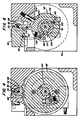
shaft 38 extends axially throughout the length ofhousing 34 and journaled therein by means ofbearings 52.Knotter unit 12 actually contains four regions in which work is performed.Knotter housing 34 includes a central region A wherein the knotting ofwires knotter unit 12, region D, is provided a cutter to sever the portion ofwire 32 which is attached to the wire supply. - As was described above, the
end portion 30 ofwire 22 is fed throughknotter unit 12 from left to right as viewed in Figure 3. Left wire yoke 53 and left wire guide 54 are provided in the upper left region ofknotter housing 34 to receivewire end portion 30 as it is introduced intoknotter 12.Wire end 30 then passes throughtwister pinion 56 which has a longitudinally extending and laterally opening slot in which both of the wires to be twisted are received in lapped generally parallel relation. Thewire end 30 then passes through rightwire guide member 58 and right wire yoke 59 and is retained by the gripping means 118, described below.Cover plate 60 is provided to retainwires Wires twister pinion 56 by means of spring biasedhorizontal finger 62. It is notable that the left yoke 53 and right yoke 59 in whichwires wire 30 abovewire 32. Such a configuration holds the ends ofwires right wire guide 58 are configured to be pivotable withinhousing 34 and are spring-biased therein. As such, wire guides 54 and 58 are effective to completely constrain and guide the feeding ofwire end portion 30 while being movable during the twisting ofwires - In order to accomplish the knotting of
wires shaft 38 in its first direction, there is provided in the central region of housing 34 afirst drive hub 64 which is splined toshaft 38.Drive hub 64 is provided with a stepped region 66 on the outer peripheral surface thereof. Coaxial with and surroundingfirst drive hub 64 istwister gear 68 which meshes withtwister pinion 56. A central cut-out area oftwister gear 68 is provided to accommodate spring biased pawl 70 which is affixed to backingplate 71 which is in turn secured to the reverse side oftwister gear 68. As such, whenshaft 38 is rotated in a counterclockwise direction as viewed in Figure 4, pawl 70 engages stepped region 66 onfirst drive hub 64 thereby causing the rotation oftwister gear 68 therewith and the rotation oftwister pinion 56 which twistswires shaft 38 is rotated in a clockwise direction as viewed in Figure 4, the pawl 70 slips around the remainder of the periphery offirst drive hub 64 andtwister gear 68 andtwister pinion 56 are not rotated. In order to assure the stationary position oftwister pinion 56 during rotation ofshaft 38 in the reverse direction,finger 62 also serves as an anti-back rotation dog to engage aflat surface 74 on thetwister pinion 56 to prevent its rotation. Accordingly, astwister pinion 56 is prevented from reverse rotation so istwister gear 68, which causes pawl 70 to ride harmlessly onfirst drive hub 64. - It will be apparent to one skilled in the art that in terms of mechanical efficiency and accurate repeatability it is preferable that all knotting occur during the forward stroke of the
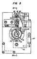
piston cylinder 48 and hence while rotation in the first direction ofshaft 38, and the cutting and ejection of the knottedwires cylinder 48 and the reverse rotation ofshaft 38. As such, as soon as the piston ofcylinder 48 begins its retraction stage thereby rotatingshaft 38 in its reverse direction, the cutting function must be activated. The cutting ofwire 32 which up to this point has remained connected to the wire supply occurs in the extreme left portion, region D ofknotter 12, as viewed in Figures 3 and 7. The cutting function ofknotter 12 is motivated by means of key 72 which fits into a notch onshaft 38 as viewed in Fig. 5. Spring-biasedpawl 73 is mounted on acutter cam 74 which is coaxial with and mounted onshaft 38. As such, whenshaft 38 is moved in its reverse direction, key 72 engagespawl 73 which causes the movement in the reverse direction ofcutter cam 74 which is coaxial withshaft 38. To prevent its movement when such in undesirable,cutter cam 74 is provided with a detent 76, the action of which is described below, on the opposite side thereof from the lobe ofcutter cam 74.Protective collar 78 is affixed to the left end ofshaft 38 outboard ofcutter cam 74 to retain the same. Pivotally attached to the left portion ofhousing 34 iscutter lever 80 having a cuttingsurface 82 incorporated into the upper region thereof and aroller cam follower 84 journaled on its opposite end region. A detent 86 is formedadjacent roller 84 oncutter lever 80. In operation,roller cam follower 84 is configured to be in operative engagement with the cam surface ofcutter cam 74. Accordingly, whenshaft 38 is rotated in its reverse direction, which is seen as counterclockwise in Figure 5,roller cam follower 84 rides alongcutter cam 74 thereby pivotingcutter lever 80 about its pivot point and movingcutter surface 82 relative to a corresponding fixedcutter surface 88 which is affixed tohousing 34. As such,wire 32 is cut by the movement ofcutter surface 82 in cooperation withstationary surface 88. Any reverse rotation ofcutter cam 74 is prevented by the engagement of its detent 76 with detent 86 oncutter lever 80. - Immediately following such cutting of
wire 32 thereby serving to sever the knotted region ofwire 22 consisting ofwires knotter 12. Such removal is accomplished by ejector units, generally 90, which are provided in the outboard regions, B and C, ofhousing 34. As the operation of bothejector units 90 is identical, only the operation ofright ejector unit 90, as viewed in Figure 3, will be described in detail. The action ofejector unit 90 is also motivated byshaft 38 during its reverse rotation by means of anejector drive hub 92 which is also splined toshaft 38 and includes a steppedregion 94 on the peripheral surface thereof. Coaxial with and surroundingejector drive hub 92 ishub 96 which includes a cut-out peripheral area to accommodate a spring-biasedejector pawl 98 which is affixed thereto. As such, whenshaft 38 is rotated in its reverse direction, which is clockwise as viewed in Figure 6,ejector drive hub 92 is similarly rotated which causesstep 94 to engagepawl 98 in order to causehub 96 to rotate in the reverse direction. - Rotatably attached to the face of
drive hub 96 isroller 100. In addition, the outer peripheral surface ofhub 96 includes an additional steppedarea 102. Spring-biasedpin 104 is provided inhousing 34 to cooperate withstep 102 in the outer periphery ofhub 96 to prevent the rotation thereof whenshaft 38 is rotated in its first direction. Immediately adjacent to drivehub 96 is a generally "U"-shapedejector member 106 having afirst cam surface 108 disposed on one leg thereof and asecond cam surface 110 disposed on the other leg. In addition, abeveled region 112 is provided adjacent the upperflat surface 114 ofejector member 106. As was mentioned above, pivotally affixed to the upper portion ofhousing 34 iscover member 60.Cover 60 is provided with aroller 116 joumaled in the lower portion of the top region thereof. In addition,cover member 60 is normally biased closed by means ofsprings 117. - As was stated above, the
present knotter unit 12 is provided with a pivotablewire gripping means 118. Thegripper 118 consists of a two-armed lever pivoted at its central point onhousing 34. One arm ofgripper 118 includes a gripping surface 120 in facing relation to wire 30 (shown schematically in Figure 7) and theother arm 122 includes a cam surface 124. Spring 126 is provided to normally bias gripping surface 120 towardsurface 127 on right yoke 59. - Accordingly, the entire process of ejecting the knotted
wires shaft 38 begins its reverse rotation,ejector drive hub 92 is rotated clockwise as viewed in Figure 6 which causes the engagement ofpawl 98 with steppedsurface 94 thereby causing the clockwise rotation ofhub 96 and the movement ofroller 100 about the axis ofshaft 38. However, in order to allow a sufficient passage of time to accomplish the cutting ofwire 32,roller 100 does not engagecam 108 for a period of dwell. Whenroller 100 reachesfirst ejector cam 108, it causesejector member 106 to be lifted. Such lifting causes coverroller 116 to ride up onbeveled surface 112 thereby causingcover 60 to be pivoted and opened against the action of its biasing springs 117. Simultaneously, a projection 128 on the underside ofcover 60 engages cam surface 124 ongripper 118 thereby releasing gripping surface 120 from engagement withwire end 30. Following the opening ofcover 60, theflat surface 114 ofejector member 106 reaches the knot formed betweenwires knotter unit 12. Asejector drive hub 92 continues to rotate in the reverse direction,roller 100 engages and rides onsecond cam surface 110 which causesejector member 106 to be positively driven downward into its retracted position.Cover 60 is then closed by means of cover biasing springs 117. At this point, theknotter unit 12 is ready to apply the next knot aspin 104 retainshub 96 in a stationary position during rotation ofshaft 38 in its first direction. During rotation in the first direction,roller 100 is preferably maintained in contact withcam surface 110 thereby assuring the continuing retraction ofejector member 106 during twisting.
Claims (15)
movable wire guides (54, 58) disposed within said housing (34) inboard of said wire yokes (53, 59), said wire guides (54, 58) being spring biased so as to allow sufficient displacement thereof away from said wire path to allow the twisting of wires (22; 30, 32) about one another.
Applications Claiming Priority (2)
| Application Number | Priority Date | Filing Date | Title |
|---|---|---|---|
| US06/714,744 US4577554A (en) | 1985-03-22 | 1985-03-22 | Knotting apparatus for wire strapping machine |
| US714744 | 1996-09-16 |
Publications (2)
| Publication Number | Publication Date |
|---|---|
| EP0199898A1 EP0199898A1 (en) | 1986-11-05 |
| EP0199898B1 true EP0199898B1 (en) | 1990-06-27 |
Family
ID=24871288
Family Applications (1)
| Application Number | Title | Priority Date | Filing Date |
|---|---|---|---|
| EP86101212A Expired EP0199898B1 (en) | 1985-03-22 | 1986-01-30 | Knotting apparatus for wire strapping machine |
Country Status (3)
| Country | Link |
|---|---|
| US (1) | US4577554A (en) |
| EP (1) | EP0199898B1 (en) |
| DE (1) | DE3672229D1 (en) |
Cited By (1)
| Publication number | Priority date | Publication date | Assignee | Title |
|---|---|---|---|---|
| CN111846336A (en) * | 2020-07-31 | 2020-10-30 | 杭州品胜胶带厂 | Automatic rope binding device for packages convenient to transport |
Families Citing this family (21)
| Publication number | Priority date | Publication date | Assignee | Title |
|---|---|---|---|---|
| US4953598A (en) * | 1989-04-13 | 1990-09-04 | Mccavey William M | Wire tying tool for concrete reinforcing steel |
| US5217049A (en) * | 1991-08-02 | 1993-06-08 | Gateway Construction Company, Inc. | Power rebar typing tool |
| US5431196A (en) * | 1994-01-03 | 1995-07-11 | Belcan Specialty Equipment Engineering Division Of Belcan Engineering Groups, Inc. | Power rebar tying tool |
| US6283017B1 (en) * | 1995-10-24 | 2001-09-04 | L & P Property Management Company | Apparatus for tying and binding bales of compressed materials |
| US5704283A (en) * | 1995-10-24 | 1998-01-06 | L & P Property Management Company | Automatic tie system for baler |
| US6173932B1 (en) | 1998-06-04 | 2001-01-16 | L&P Property Management Company | Mounting device for mounting a hand tying device to a bale of compressed material |
| US6009646A (en) * | 1998-06-05 | 2000-01-04 | L&P Property Management Company | Apparatus for tying and binding bales of compressed materials |
| US6032575A (en) * | 1998-07-16 | 2000-03-07 | L&P Property Management Company | Automatic baler with tying system having simultaneously engaged twister pinions |
| US6968779B2 (en) | 2000-03-15 | 2005-11-29 | Enterprises International, Inc. | Apparatus and methods for wire-tying bundles of objects |
| US6584891B1 (en) * | 2000-03-15 | 2003-07-01 | Enterprises International, Inc. | Apparatus and methods for wire-tying bundles of objects |
| US7373877B2 (en) * | 2004-04-14 | 2008-05-20 | Accent Packaging, Inc. | Wire strapper for waste material baler |
| US7389724B2 (en) * | 2004-12-17 | 2008-06-24 | Marathon Equipment Company | Waste baling method and apparatus |
| US7124784B2 (en) * | 2004-12-30 | 2006-10-24 | L&P Property Management Company | Ejector drive hub apparatus and method |
| US8397632B2 (en) | 2010-03-04 | 2013-03-19 | L & P Property Management Company | Knotter assembly |
| US9045245B2 (en) | 2010-03-04 | 2015-06-02 | L&P Property Management Company | Knotter assembly |
| US10684595B2 (en) | 2013-09-04 | 2020-06-16 | Accent Wire Holdings, LLC | Control user interface for tying system |
| US9278772B2 (en) | 2014-02-20 | 2016-03-08 | L&P Property Management Company | Combination wire and plastic strapping device |
| US11040789B2 (en) | 2014-02-20 | 2021-06-22 | Accent Wire Holdings Llc | Combination wire and plastic strapping device |
| US10351274B2 (en) | 2014-02-20 | 2019-07-16 | Accent Packaging Inc. | Combination wire and plastic strapping device |
| US9359094B2 (en) | 2014-03-10 | 2016-06-07 | L & P Property Management Company | Gripping mechanism |
| CN113291521B (en) * | 2021-05-25 | 2023-04-11 | 青岛港国际股份有限公司 | Twisting device |
Family Cites Families (9)
| Publication number | Priority date | Publication date | Assignee | Title |
|---|---|---|---|---|
| US2812707A (en) * | 1950-06-06 | 1957-11-12 | Leo M Harvey | Tying machines for packages and the like |
| US2982199A (en) * | 1954-08-26 | 1961-05-02 | Leo M Harvey | Tying machines for packages and the like |
| US2922359A (en) * | 1958-01-16 | 1960-01-26 | United States Steel Corp | Knotter for automatic wire-tying machine |
| US3037534A (en) * | 1959-08-11 | 1962-06-05 | United States Steel Corp | Wire-tying machine |
| US3060841A (en) * | 1959-09-09 | 1962-10-30 | Metaverpa Nv | Mechanism for tying together the ends of a wire passed round a package |
| US3037535A (en) * | 1960-02-10 | 1962-06-05 | United States Steel Corp | Knotter mechanism for automatic wire-tying machine |
| US3232216A (en) * | 1963-04-29 | 1966-02-01 | Devco Inc | Wire binding machine |
| US3327618A (en) * | 1965-05-17 | 1967-06-27 | Package Sealing Company Export | Package binding machines |
| SE367603B (en) * | 1972-10-17 | 1974-06-04 | Sunds Ab |
-
1985
- 1985-03-22 US US06/714,744 patent/US4577554A/en not_active Expired - Lifetime
-
1986
- 1986-01-30 DE DE8686101212T patent/DE3672229D1/en not_active Expired - Lifetime
- 1986-01-30 EP EP86101212A patent/EP0199898B1/en not_active Expired
Cited By (1)
| Publication number | Priority date | Publication date | Assignee | Title |
|---|---|---|---|---|
| CN111846336A (en) * | 2020-07-31 | 2020-10-30 | 杭州品胜胶带厂 | Automatic rope binding device for packages convenient to transport |
Also Published As
| Publication number | Publication date |
|---|---|
| US4577554A (en) | 1986-03-25 |
| EP0199898A1 (en) | 1986-11-05 |
| DE3672229D1 (en) | 1990-08-02 |
Similar Documents
| Publication | Publication Date | Title |
|---|---|---|
| EP0199898B1 (en) | Knotting apparatus for wire strapping machine | |
| US4502905A (en) | Tying machine and method | |
| US4120239A (en) | Strapping machine | |
| US3232217A (en) | Strapping machine | |
| US7380574B2 (en) | Wire strapper for waste material baler | |
| CA2671933C (en) | Apparatus and methods for wire-tying bundles of objects | |
| EP0460880B1 (en) | Twist tie feed device | |
| US3636861A (en) | Strapping machine | |
| US3450028A (en) | Strapping apparatus | |
| US3157109A (en) | Tying machine | |
| CN212738621U (en) | Packing head of horizontal high-speed wire packing machine | |
| GB1569276A (en) | An automatic tying machine | |
| US3768397A (en) | Strapping machine | |
| US1969160A (en) | Banding machine | |
| US3045584A (en) | Twine wrapping and jointing machines for tying bundles | |
| US4689938A (en) | Automatic wrapping machine comprising a tensioning and fastening device | |
| US6837156B2 (en) | Twist tie feed device | |
| US3611916A (en) | Bundle-binding machine and process | |
| CZ288553B6 (en) | Fastener | |
| JPH021726B2 (en) | ||
| US11713144B2 (en) | Wire release mechanism | |
| US3039380A (en) | Wire tying machines | |
| GB2596581A (en) | Wire release mechanism | |
| JP3434548B2 (en) | Apparatus and method for supplying, cutting and tying twisted ribbons | |
| GB726514A (en) | Improvements in bundle tying apparatus |
Legal Events
| Date | Code | Title | Description |
|---|---|---|---|
| PUAI | Public reference made under article 153(3) epc to a published international application that has entered the european phase |
Free format text: ORIGINAL CODE: 0009012 |
|
| AK | Designated contracting states |
Kind code of ref document: A1 Designated state(s): DE GB IT NL |
|
| PUAB | Information related to the publication of an a document modified or deleted |
Free format text: ORIGINAL CODE: 0009199EPPU |
|
| PUAF | Information related to the publication of a search report (a3 document) modified or deleted |
Free format text: ORIGINAL CODE: 0009199SEPU |
|
| R17D | Deferred search report published (corrected) |
Effective date: 19861210 |
|
| RA1 | Application published (corrected) |
Date of ref document: 19861210 Kind code of ref document: A1 |
|
| 17P | Request for examination filed |
Effective date: 19870804 |
|
| RAP1 | Party data changed (applicant data changed or rights of an application transferred) |
Owner name: U.S. STEEL SUPPLY, INC. |
|
| 17Q | First examination report despatched |
Effective date: 19880715 |
|
| GRAA | (expected) grant |
Free format text: ORIGINAL CODE: 0009210 |
|
| AK | Designated contracting states |
Kind code of ref document: B1 Designated state(s): DE GB IT NL |
|
| ITF | It: translation for a ep patent filed |
Owner name: BARZANO' E ZANARDO ROMA S.P.A. |
|
| REF | Corresponds to: |
Ref document number: 3672229 Country of ref document: DE Date of ref document: 19900802 |
|
| PGFP | Annual fee paid to national office [announced via postgrant information from national office to epo] |
Ref country code: GB Payment date: 19901227 Year of fee payment: 6 |
|
| PGFP | Annual fee paid to national office [announced via postgrant information from national office to epo] |
Ref country code: DE Payment date: 19910130 Year of fee payment: 6 |
|
| ITTA | It: last paid annual fee | ||
| PLBE | No opposition filed within time limit |
Free format text: ORIGINAL CODE: 0009261 |
|
| STAA | Information on the status of an ep patent application or granted ep patent |
Free format text: STATUS: NO OPPOSITION FILED WITHIN TIME LIMIT |
|
| 26N | No opposition filed | ||
| PG25 | Lapsed in a contracting state [announced via postgrant information from national office to epo] |
Ref country code: GB Effective date: 19920130 |
|
| PGFP | Annual fee paid to national office [announced via postgrant information from national office to epo] |
Ref country code: NL Payment date: 19920131 Year of fee payment: 7 |
|
| GBPC | Gb: european patent ceased through non-payment of renewal fee | ||
| PG25 | Lapsed in a contracting state [announced via postgrant information from national office to epo] |
Ref country code: DE Effective date: 19921001 |
|
| PG25 | Lapsed in a contracting state [announced via postgrant information from national office to epo] |
Ref country code: NL Effective date: 19930801 |
|
| NLV4 | Nl: lapsed or anulled due to non-payment of the annual fee | ||
| PG25 | Lapsed in a contracting state [announced via postgrant information from national office to epo] |
Ref country code: IT Free format text: LAPSE BECAUSE OF NON-PAYMENT OF DUE FEES Effective date: 20050130 |