EP0199312B1 - Method and apparatus for determining skin fricton or viscosity of a liquid on a model or other object in contact with the flowing liquid - Google Patents
Method and apparatus for determining skin fricton or viscosity of a liquid on a model or other object in contact with the flowing liquid Download PDFInfo
- Publication number
- EP0199312B1 EP0199312B1 EP86105414A EP86105414A EP0199312B1 EP 0199312 B1 EP0199312 B1 EP 0199312B1 EP 86105414 A EP86105414 A EP 86105414A EP 86105414 A EP86105414 A EP 86105414A EP 0199312 B1 EP0199312 B1 EP 0199312B1
- Authority
- EP
- European Patent Office
- Prior art keywords
- sensor
- liquid
- light beam
- light
- flow
- Prior art date
- Legal status (The legal status is an assumption and is not a legal conclusion. Google has not performed a legal analysis and makes no representation as to the accuracy of the status listed.)
- Expired - Lifetime
Links
- 239000007788 liquid Substances 0.000 title claims description 70
- 238000000034 method Methods 0.000 title claims description 27
- 238000005259 measurement Methods 0.000 claims description 19
- 230000008859 change Effects 0.000 claims description 12
- 238000011156 evaluation Methods 0.000 claims description 10
- 239000004020 conductor Substances 0.000 claims description 6
- 238000012937 correction Methods 0.000 claims description 4
- 239000013307 optical fiber Substances 0.000 claims description 3
- 238000001514 detection method Methods 0.000 claims description 2
- 239000010408 film Substances 0.000 description 7
- 238000012545 processing Methods 0.000 description 4
- 239000012530 fluid Substances 0.000 description 3
- 230000001133 acceleration Effects 0.000 description 2
- 230000008901 benefit Effects 0.000 description 2
- 230000001771 impaired effect Effects 0.000 description 2
- 238000009434 installation Methods 0.000 description 2
- 239000000463 material Substances 0.000 description 2
- 230000009471 action Effects 0.000 description 1
- 230000015572 biosynthetic process Effects 0.000 description 1
- 238000006243 chemical reaction Methods 0.000 description 1
- 230000003247 decreasing effect Effects 0.000 description 1
- 230000001419 dependent effect Effects 0.000 description 1
- 238000010586 diagram Methods 0.000 description 1
- 239000003814 drug Substances 0.000 description 1
- 238000012854 evaluation process Methods 0.000 description 1
- 239000011552 falling film Substances 0.000 description 1
- 239000011521 glass Substances 0.000 description 1
- 230000005484 gravity Effects 0.000 description 1
- 230000003993 interaction Effects 0.000 description 1
- 239000011159 matrix material Substances 0.000 description 1
- 230000003287 optical effect Effects 0.000 description 1
- 229920002545 silicone oil Polymers 0.000 description 1
- 239000007787 solid Substances 0.000 description 1
- 230000002123 temporal effect Effects 0.000 description 1
- 230000007704 transition Effects 0.000 description 1
Images


Classifications
-
- G—PHYSICS
- G01—MEASURING; TESTING
- G01N—INVESTIGATING OR ANALYSING MATERIALS BY DETERMINING THEIR CHEMICAL OR PHYSICAL PROPERTIES
- G01N13/00—Investigating surface or boundary effects, e.g. wetting power; Investigating diffusion effects; Analysing materials by determining surface, boundary, or diffusion effects
-
- G—PHYSICS
- G01—MEASURING; TESTING
- G01M—TESTING STATIC OR DYNAMIC BALANCE OF MACHINES OR STRUCTURES; TESTING OF STRUCTURES OR APPARATUS, NOT OTHERWISE PROVIDED FOR
- G01M10/00—Hydrodynamic testing; Arrangements in or on ship-testing tanks or water tunnels
-
- G—PHYSICS
- G01—MEASURING; TESTING
- G01N—INVESTIGATING OR ANALYSING MATERIALS BY DETERMINING THEIR CHEMICAL OR PHYSICAL PROPERTIES
- G01N11/00—Investigating flow properties of materials, e.g. viscosity, plasticity; Analysing materials by determining flow properties
Definitions
- the invention relates to a method for determining the wall shear stress or the viscosity of liquids on models and other flow-around bodies, in which a viscous transparent liquid is applied in a layer to the surface of the body at the measuring point and the thickness and / or change in the surface inclination of the layer is detected with a light beam.
- the invention also shows a device for carrying out this method with a light source, a layer of a viscous transparent liquid and a photodiode for detecting the reflected light beam.
- a body with a flow around it can be a wind tunnel model, but also an original device on the ground or in the air, for example a car or an aircraft.
- the data to be determined experimentally are often used to check universal laws and theoretical models, so that it is necessary to measure the wall shear stress with appropriate accuracy and without affecting the flow.
- a point-like measurement at the individual measuring point is thus possible.
- the fact is simplified that a thin oil film undergoes a change in thickness y in the direction of flow due to the wall shear stress T at constant flow conditions with the time t on the path element d, according to the formula is equal to the inverse wall shear stress T , where ⁇ means the viscosity of the oil film used.
- the method boils down to determining the two variables t (in the range of seconds) and y (in the range of approximately 100 ⁇ m) with known ⁇ and d. The use of this known method has numerous disadvantages.
- the flow rate Q of the liquid is determined through a capillary with the inner radius R and the length L under the driving pressure difference AP using the law of Hagen-Poiseuille and the viscosity is calculated from this using the following formula:
- Another method for determining the viscosity of liquids has been described by LH Tanner, "The measurement of viscosity by optical technics applied to a falling film", Journal of Physics E. Scientific Instruments (1976), Vol. 9, p. 967, in which the viscosity can be determined optically.
- the method uses the relationship according to the above formula, an interferometric determination of the layer thickness d of a liquid with the viscosity n being carried out.
- a light beam is directed from the outside onto a liquid flowing down a vertical wall and the reflected beam is detected in a photodetector.
- the light beam is reflected once at the interface between liquid and vertical wall and a second time at the interface between liquid and air. Both reflected rays interfere with each other.
- a change in intensity light-dark-light is determined in the photodetector, which changes over time with a decreasing thickness slowed down.
- the viscosity can be determined by counting.
- the method described first can be refined and then achieves a fairly high degree of accuracy; however, larger quantities of the liquid to be examined are required. Viscosity determinations in the molecular range (medicine) are not possible. In contrast, this method is advantageous insofar as non-transparent liquids can also be examined.
- the beam reflected at the interface between the liquid and the solid body is impaired by the thickness of the liquid layer, so that different interference conditions result.
- the accuracy of this method is limited in that the point of impact of the jet sent onto the liquid depends on the layer thickness of the liquid and is therefore not constant. There are also adjustment difficulties.
- the invention has for its object to provide a method and an apparatus with which it is possible to measure the wall shear stress absolutely or relatively in its size, direction and distribution without significant disturbance of the flow or the viscosity of liquids.
- the measurement should also be repeatable without interrupting the flow.
- the measurement should also be carried out in dynamic examinations, e.g. on flying bodies.
- this is achieved in that the light beam from the interior of the body around which flow is directed in the direction of the surface of the body and into the layer of the viscous liquid and that the reflected light beam is collected in the interior of the body around which flow.
- the invention thus turns away from the prior art and uses the light beam from the other side - that is, from the inside - to determine the wall shear stress absolutely.
- This has the great advantage that the measurement is independent of the external conditions, e.g. the formation of a wind tunnel, and that the measuring device can be carried along with the body or body around which it flows, in a simple manner, e.g. a measurement is to be carried out on a moving car or an aircraft. The flow around the body is not affected by the measuring device.
- a major advantage of the method according to the invention is that each measurement can be repeated without interrupting the flow conditions. It is very easy to re-form the layer of viscous liquid to repeat the measurement or, if necessary, to use a liquid of a different viscosity.
- the viscous liquid in addition to the light beam, is also directed from the inside of the body to which the flow is flowing to the surface of the body. This means that the layer of viscous liquid can be re-formed at any time without affecting the flow. It is also possible to use several light beams in connection with a line for the viscous liquid in order to determine the distribution of the wall shear stress. The wall shear stress at each measuring point can be read off immediately.
- the angle of the illuminating beam advantageously always remains constant regardless of the layer thickness and the layer inclination.
- the device for carrying out the method works with a light source, a layer of a viscous transparent liquid and a photodiode for detecting the reflected light beam.
- the device for determining the thickness and / or surface inclination has a planar sensor that can be installed flush with the surface of the body around which the flow is flowing, and that a channel for applying the liquid that ends in the sensor surface and at least one light line that also ends in the sensor surface are provided for supplying the light beam and for deriving the reflected light beam.
- a Michelson interferometer, a photodiode and a downstream evaluation electronics can be provided for the detection.
- the new area sensors can be used again and again, i.e.
- the areal sensor replaces part of the surface of the model or the body around which it flows and thus itself forms part of the surface of the body around which it flows at the measuring point.
- the entire measuring device or its essential parts are accommodated in the interior of the body around which the flow flows, so that the flow around the body cannot be impaired thereby.
- the device When determining the viscosity of liquids, the device is rotated by 90 °, so that the measuring point or the surface of the sensor is arranged vertically. In this new arrangement and through the use of the beam path from the inside, the angle of the illuminating beam always remains constant regardless of the layer thickness and the layer inclination.
- Optical fiber cables can be provided as the light guide and a laser as the light source. This makes it possible to use the sensor even under difficult installation conditions.
- the sensor can also have a plurality of light lines ending in the sensor surface in order to determine the distribution of the wall shear stress in the surface.
- a plane is defined by the ends of at least three light pipes, so that their inclination can also advantageously be determined.
- Another measuring point can be used for checking. It is also possible to use other channels assigned to the individual measuring points for liquids with different viscosities. There can also be a resolution of less mm 2 at local Absolute determination of the wall shear stress can be achieved.
- the determination of the wall shear stress is also possible with the invention in the case of complicated flows, in particular 3-D flows, flows with pressure or shear stress gradients.
- the senor can consist of light-conducting material and extend normally to the surface around which the body flows.
- the sensor ends there in a transparent surface in which a deflection prism for the light beam to be supplied and a position-free diode for the reflected light beam are provided without reflection.
- the position diode can be a four-quadrant diode, a ZD line matrix or the like. be. This simplifies the device with which only the change in the surface inclination can be determined.
- the sensor made of light-conducting material can have a block shape and have a beam-dividing cut. Corrective optics for expanding and / or adjusting the divided beam are provided on the sensor.
- the sensor is assigned a second sensor made of light-conducting material, which is arranged at a right angle to it, so that in the area of this second sensor the divided beam and the reflected beam are brought into interference with one another.
- the sensor with its surface over which the liquid flows is arranged vertically.
- the sensor (1) shown in Figure 1 consists of a planar element of a certain extent, which can be installed with its surface (2) flush with the surface (3) of the body (4) around which it flows. The flow around the body (4) takes place on the outside thereof according to the arrow (5).
- a channel (6) ends in the sensor (1) and is connected to a tube (7).
- the tube (7) and the channel (6) serve to introduce a transparent viscous liquid as a layer (8) onto the surface (2) and thus into the surface (3) of the body (4) around which it flows.
- the layer (8) is drawn here with the same thickness over the areal extent of the sensor (1) and will experience a local change in thickness as a result of the flow around it (arrow).
- a plurality of light lines (9) terminate in the sensor (1) or its surface (2), which are designed in particular as optical fiber cables. These light lines (9) are connected to an arm (10) of a Michelson interferometer (11).
- the ends (12) of the light pipes (9) in the surface (2) can be arranged in the manner of a square, as shown in FIG. 2, the end (13) of the channel (6) or the tube (7) in the center may be appropriate.
- a laser (14) is provided, which is followed by a beam splitter (15).
- the light is fed to the Michelson interferometer (11) with a light guide (16).
- a photodiode (17) and evaluation electronics (18) are provided for evaluating the reflected light beam.
- a certain amount of the liquid is discharged through the tube (7) and the channel (6) on the surface (2) of the sensor (1) before or during the occurrence of the flow conditions according to arrow (5), so that it spreads out on the surface.
- the light generated by the laser (14) passes via the beam splitter (15), the light pipe (16) to the Michelson interferometer (11) and from its arm (10) via the light pipe (9) into the end (12), thus also in the surface and thus in the layer (8) of the viscous liquid.
- changes in brightness of the reflected light occur on the photodiode (17) and are registered due to interference in the photodiode (17) and evaluated in the downstream evaluation electronics (18).
- the light enters from the arms (10) of the interferometer (11) in the free ends (12) of the light pipes (9) into the layer (8) of the liquid and is partially reflected at the boundary between the liquid and the air flowing around it.
- changes in brightness are detected in the photodiode (17) when the light path changes due to the changing thickness of the layer (8) of the liquid under the flow conditions.
- the change in thickness of the layer (8) can be determined simultaneously at four points on the sensor, namely at the four ends (12) of the light pipes (9). This is done with the aid of the evaluation electronics (18) as a function of time, which also continuously calculates the wall shear stress and its direction from the different changes in thickness at the four points.
- the device shown in Figure 3 uses a sensor (1) made of a translucent body, in particular glass, which can be designed as a round rod.
- This sensor (1) is again used with its surface (2) flush with the surface (3) of the body (4) around which it flows. It also extends normal to the surface (3) and ends in a surface (19), which can in particular be arranged parallel to the surface (2).
- the sensor (1) may have the length L here.
- the viscous liquid can be dispensed onto the surface (2) via the channel (6), so that the layer (8) is formed as a result of the flow conditions according to arrow (5), which layer here is wedge-shaped with the angle y as a result of the flow conditions trains and changes.
- a laser beam (20) is focused with a focusing lens (21) onto a position diode (25) and enters the sensor (1) through an entrance window (22) and a deflecting prism (23) at an angle a.
- the light beam passes through the surface (2) into the layer (8) of the liquid and is partially reflected at the boundary of the liquid and the fluid flowing around the body (4) according to arrow (5), whereby it is reflected back onto the surface (19) and arrives there at a point of impact (24) on the position diode (25).
- the point of impact (24) on the position diode (25) is predetermined by the angle a and the length L of the sensor and the layer thickness d.
- the layer of oil e.g. silicone oil
- the layer (8) changes at an angle of inclination y relative to the surface (2) and thus the surface (3) of the body ( 4) sets
- the Auftrettfstelle (24) moves on the xy plane of the position diode (25).
- the position diode (25) is designed and arranged in such a way that the point of impact (24) can be determined in its xy plane, so that in addition to the angle of inclination y, the direction of inclination of the surface of the layer (8) can also be measured.
- the changes in the point of impact (24) are indicated with yx and yy, then being because the temporal change in the angle of inclination y provides the amount and the ratio yx / yy in the xy plane provides the direction of the wall shear stress. Since the light beam emerges from its surface (2) above the deflecting prism (23) at an angle a relative to the axis of the sensor (1), the angle a must be taken into account accordingly in the evaluation. However, it is also possible to drill through the position diode (25) and to work without a deflection prism (23). The laser beam (20) then enters the sensor (1) centrally via the bore of the position diode (25) and can be detected on the position diode (25) with a corresponding deflection.
- a laser beam (20) is fed to processing optics (26) via a light guide (9), which widens the light beam in the usual way and images it on a detector (27).
- the processed light beam passes through the sensor (1), which has a beam-splitting section (28) and thus has the function of a conventional beam splitter cube.
- the light beam is partially reflected at the interface between liquid and air of the layer (8) of the liquid and ultimately reaches the detector (27) as a reflected beam (29), which is formed from four quadrant photodiodes can.
- the deflection of the reflected beam (29) is detected both in the vertical and in the horizontal direction by means of evaluation electronics (18) connected downstream of the detector (27).
- a divided beam (30) is guided through the beam-splitting cut (28) to a correction lens (32) and expanded there, this beam also passing from the sensor (1) into the second sensor (31) and ultimately also onto the detector ( 27) arrives, but in an expanded form.
- the reflected beam (29) deflected towards the detector (27) interferes with the divided beam (30), which can possibly be adjusted accordingly via the correction optics (32) .
- This arrangement thus functions like a Michelson interferometer, and with the aid of the detector (27) changes in intensity can be observed which result from changes in path length in the layer (8) of the viscous liquid.
- the liquid can be fed in via a line or a tube (7) in such a way that it ultimately reaches the surface of the body being flowed around as a layer (8) and thus to the measuring point. Two evaluation methods are possible to determine the wall shear stress.
- the deflection in the detector (27) is detected in two directions as a function of time.
- the number of fluctuation periods as a function of time provides information about the wall shear stress.
- the device according to FIG. 4 can of course also be used in an arrangement rotated through 90 ° for determining the viscosity of liquids.
- FIG. 5 shows a similarly structured arrangement for determining the viscosity of liquids.
- a laser beam (20) is fed to processing optics (26) via a light guide (9), which are designed here as focusing optics to image the reflected beam (29) on the detector (27).
- the beam processed in this way by the processing optics (26) passes through the sensor (1), which is designed as a transparent block and has a beam-splitting section (28).
- the sensor (1) which is designed as a transparent block and has a beam-splitting section (28).
- This also means that the beam introduced is divided here into a reflected beam (29) and a split beam (30).
- the processed beam is first partially reflected on the vertical surface (2) of the sensor (1) between the material of the transparent block and the liquid, and partly deflected at the beam-dividing cut (28).
- Both beams ultimately pass through the second sensor (31) and reach the detector (27), which is designed as a photodetector.
- Another part of the processed beam is reflected at the boundary layer between liquid and air and, as a reflected beam (29), also reaches the second sensor (31) and thus the detector (27) via the beam-dividing cut (28).
- the divided beam (30) can be expanded with correction optics (32) and adjusted and also directed towards the detector (27), so that interference occurs there.
- the partial beam reflected in itself at the interface between the sensor (1) and the air interferes with the deflected beam (30) at the detector (27).
- the result of this interference is either a large or small light intensity - regardless of the time, i.e. constant.
- a tear (37) forms on the surface due to gravity (2), which is arranged vertically, flows down. Due to the interaction of the various forces, a new interface between air and liquid is formed that is not parallel to the surface (2). The reflected and deflected beam (29) arises at this interface.
- the thickness d of the interface is at time t at a distance x from the outflow opening (35) according to the formula reproduced, the viscosity ⁇ of the liquid being included as the material constant in addition to the constant gravitational acceleration g and the density p of the liquid.
- the reflected beam (29) is now essentially reflected at this new interface between liquid and air. Since the thickness d changes with time t, the interference conditions also change continuously. Now the light intensity changes as a function of time t, a change in intensity light-dark-light corresponding to a change in thickness of ⁇ / 2. Since the time t is in the denominator in the formula given above, the thickness changes are large for small times. As a result, the changes in intensity are also very rapid and can only be registered using electronic means, for example in the downstream evaluation electronics (18). For very large times t, the change from light-dark-light takes hours, ie there are changes in thickness in the molecular range.
- the gravitational force must be known exactly for the measurement.
- Surface (2) should be vertical so that gravitational acceleration g can act accordingly.
- the surface (2) is expediently aligned vertically using a spirit level (38).
- the entire device is housed in a thermostatted container (39).
Landscapes
- Physics & Mathematics (AREA)
- General Physics & Mathematics (AREA)
- Health & Medical Sciences (AREA)
- Life Sciences & Earth Sciences (AREA)
- Chemical & Material Sciences (AREA)
- Analytical Chemistry (AREA)
- Biochemistry (AREA)
- General Health & Medical Sciences (AREA)
- Immunology (AREA)
- Pathology (AREA)
- Fluid Mechanics (AREA)
- Length Measuring Devices By Optical Means (AREA)
Description
Die Erfindung bezieht sich auf ein Verfahren zur Bestimmung der Wandschubspannung oder der Viskosität von Flüssigkeiten an Modellen und anderen umströmten Körpern, in dem auf die Oberfläche des Körpers an der Meßstelle eine viskose durchsichtige Flüssigkeit in einer Schicht aufgebracht und die infolge der Strömungsbedingungen eintretende Dicken- und/oder Oberflächenneigungsänderung der Schicht mit einem Lichtstrahl detektiert wird. Die Erfindung zeigt gleichzeitig eine Vorrichtung zur Durchführung dieses Verfahrens mit einer Lichtquelle, einer Schicht einer viskosen durchsichtigen Flüssigkeit und einer Photodiode zur Detektierung des reflektierten Lichtstrahls.The invention relates to a method for determining the wall shear stress or the viscosity of liquids on models and other flow-around bodies, in which a viscous transparent liquid is applied in a layer to the surface of the body at the measuring point and the thickness and / or change in the surface inclination of the layer is detected with a light beam. The invention also shows a device for carrying out this method with a light source, a layer of a viscous transparent liquid and a photodiode for detecting the reflected light beam.
Zur Beschreibung der Umströmung eines Körpers ist die genaue Kenntnis der lokalen Wandschubspannung, der Größe, der Richtung und der Verteilung nach von großer Wichtigkeit. Ein umströmter Körper kann ein Windkanalmodell, aber auch ein Originalgerät am Boden oder in der Luft, beispielsweise ein Auto oder ein Fluggerät, sein. Die dabei experimentall zu ermittelnden Daten dienen vielfach der Überprüfung universeller Gesetzmäßigkeiten und theoretischer Modellvorstellunge, so daß es notwendig ist, die Messung der Wandschubspannung mit entsprechender Genauigkeit und ohne Beeinträchtigung der Strömung durchzuführen.In order to describe the flow around a body, precise knowledge of the local wall shear stress, the size, the direction and the distribution is of great importance. A body with a flow around it can be a wind tunnel model, but also an original device on the ground or in the air, for example a car or an aircraft. The data to be determined experimentally are often used to check universal laws and theoretical models, so that it is necessary to measure the wall shear stress with appropriate accuracy and without affecting the flow.
Ein Verfahren und eine Vorrichtung der eingangs beschriebenen Art sind durch Tanner & Blows, "A study of the motion of oil films on surfaces in airflow, with application to the measurement of skin friction", Journal of Physics E: Scientific Instruments 1976, Vol. 9, pp. 194-202, bekannt. Damit ist es möglich, den Absolutwert der Wandschubspannung auf optischem Wege berührungsfrei zu messen. Zu diesem Zweck wird auf der Oberfläche des Modells von außen her ein Ölfilm aufgebracht. Ebenfalls von außen wird dann ein von einem Laser erzeugter Lichtstrahl auf den Ölfilm gerichtet. Ein Teil des Lichtstrahls reflektiert an der Oberfläche des Ölfilms, ein anderer Teil an der Oberfläche des Modells. Das reflektierte Licht wird durch eine Sammellinie gesammelt. Eine Photodiode dient zur Detektierung der wechselnden Helligkeit, die sich aufgrund von Interferenzen ergibt. Damit ist eine punktartige Messung an der einzelnen Meßstelle möglich. Zu einer solchen Messung wird vereinfachend die Tatsache ausgenutzt, daß ein dünner Ölfilm aufgrund der Wandschubspannung T bei konstanten Strömungsbedingungen mit der Zeit t auf dem Wegelement d in Strömungsrichtung eine Dickenänderung y erfährt, die nach der Formel
Zur Bestimmung der Viskosität von Flüssigkeiten sind mehrere Verfahren bekannt:Several methods are known for determining the viscosity of liquids:
Nach einem ersten Verfahren wird die Durchflußmenge Q der Flüssigkeit durch eine Kapillare mit dem Innenradius R und der Länge L unter der antreibenden Druckdifferenz AP unter Ausnutzung des Gesetzes von Hagen-Poiseuille bestimmt und daraus die Viskosität nach folgender Formel errechnet: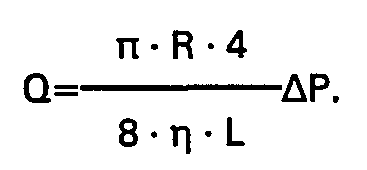
Das zuerst beschriebene Verfahren läßt sich noch verfeinern und erreicht dann eine ziemlich hohe Genauigkeit; jedoch werden größere Mengen der zu untersuchenden Flüssigkeit benötigt. Viskositätsbestimmungen im molekularen Bereich (Medizin) sind nicht möglich. Dagegen ist dieses Verfahren insoweit vorteilhaft, als auch nicht transparente Flüssigkeiten untersucht werden können.The method described first can be refined and then achieves a fairly high degree of accuracy; however, larger quantities of the liquid to be examined are required. Viscosity determinations in the molecular range (medicine) are not possible. In contrast, this method is advantageous insofar as non-transparent liquids can also be examined.
Bei dem mit Interferenz arbeitenden Verfahren nach Tanner wird der an der Grenzfläche zwischen Flüssigkeit und festem Körper reflektierte Strahl durch die Dicke der Flüssigkeitsschicht beeinträchtigt, so daß sich unterschiedliche Interferenzbedingungen ergeben. Die Genauigkeit dieses Verfahrens wird dadurch beschränkt, daß der Auftreffpunkt des auf die Flüssigkeit geschickten Strahls von der Schichtdicke der Flüssigkeit abhängig und damit nicht konstant ist. Weiterhin ergeben sich Justierschwierigkeiten.In the Tanner method using interference, the beam reflected at the interface between the liquid and the solid body is impaired by the thickness of the liquid layer, so that different interference conditions result. The accuracy of this method is limited in that the point of impact of the jet sent onto the liquid depends on the layer thickness of the liquid and is therefore not constant. There are also adjustment difficulties.
Der Erfindung liegt die Aufgabe zugrunde, ein Verfahren und eine Vorrichtung aufzuzeigen, mit denen es möglich ist, die Wandschubspannung absolut oder relativ in ihrer Größe, Richtung und Verteilung ohne wesentliche Störung der Strömung oder die Viskostiät von Flüssigkeiten zu messen. Die Messung soll auch ohne Unterbrechung der Strömung wiederholbar sein. Die Messung soll auch bei dynamischen Untersuchungen, z.B. an fliegenden Körpern, durchführbar sein.The invention has for its object to provide a method and an apparatus with which it is possible to measure the wall shear stress absolutely or relatively in its size, direction and distribution without significant disturbance of the flow or the viscosity of liquids. The measurement should also be repeatable without interrupting the flow. The measurement should also be carried out in dynamic examinations, e.g. on flying bodies.
Erfindungsgemäß wird dies dadurch erreicht, daß der Lichtstrahl aus dem Innern des umströmten Körpers in Richtung auf die Oberfläche des Körpers und in die Schicht der viskosen Flüssigkeit geleitet wird und daß der reflektierte Lichtstrahl im Innern des umströmten Körpers aufgefangen wird. Die Erfindung kehrt sich damit vom Stand der Technik ab und benutzt den Lichtstrahl gleichsam von der anderen Seite her-also vom Innern-, um die Wandschubspannung auch absolut zu bestimmen. Dies hat den großen Vorteil, daß die Messung unabhängig von den außeren Bedingungen, z.B. der Ausbildung eines Windkanals, ist und daß die Meßeinrichtung in einfacher Weise mit dem umströmten Körper bzw. in dem umströmten Körper mitgeführt werden kann, wenn z.B. eine Messung an einem fahrenden Auto oder einem Fluggerät durchgeführt werden soll. Die Umströmung des Körpers wird durch die Meßeinrichtung nicht beeinträchtigt. Ein wesentlicher Vorteil des erfindungsgemäßen Verfahrens liegt darin, daß jede Messung ohne Unterbrechung der Strömungsbedingungen wiederholbar ist. Dabei ist es sehr einfach möglich, die Schicht der viskosen Flüssigkeit zur Wiederholung der Messung neu zu bilden oder bei Bedarf auch eine Flüssigkeit anderer Viskosität zu benutzen. Zu diesem Zweck wird zusätzlich zu dem Lichstrahl auch die viskose Flüssigkeit aus dem Innern des umströmten Körpers an die Oberfläche des Körpers geleitet. Damit kann die Schicht der viskosen Flüssigkeit ohne Beeinträchtigung der Strömung jederzeit neu gebildet werden. Es ist auch möglich, mehrere Lichtstrahlen in Verbindung mit einer Leitung für die viskose Flüssigkeit zu benutzen, um die Verteilung der Wandschubspannung festzustellen. Die Wandschubspannung an jeder Meßstelle ist unmittelbar ablesbar.According to the invention, this is achieved in that the light beam from the interior of the body around which flow is directed in the direction of the surface of the body and into the layer of the viscous liquid and that the reflected light beam is collected in the interior of the body around which flow. The invention thus turns away from the prior art and uses the light beam from the other side - that is, from the inside - to determine the wall shear stress absolutely. This has the great advantage that the measurement is independent of the external conditions, e.g. the formation of a wind tunnel, and that the measuring device can be carried along with the body or body around which it flows, in a simple manner, e.g. a measurement is to be carried out on a moving car or an aircraft. The flow around the body is not affected by the measuring device. A major advantage of the method according to the invention is that each measurement can be repeated without interrupting the flow conditions. It is very easy to re-form the layer of viscous liquid to repeat the measurement or, if necessary, to use a liquid of a different viscosity. For this purpose, in addition to the light beam, the viscous liquid is also directed from the inside of the body to which the flow is flowing to the surface of the body. This means that the layer of viscous liquid can be re-formed at any time without affecting the flow. It is also possible to use several light beams in connection with a line for the viscous liquid in order to determine the distribution of the wall shear stress. The wall shear stress at each measuring point can be read off immediately.
Bei der Bestimmung der Viskosität von Flüssigkeiten bleibt vorteilhaft der Winkel des beleuchtenden Strahls unabhängig von der Schichtdicke und der Schichtneigung immer konstant.When determining the viscosity of liquids, the angle of the illuminating beam advantageously always remains constant regardless of the layer thickness and the layer inclination.
Die Vorrichtung zur Durchführung des Verfahrens arbeitet mit einer Lichtquelle, einer Schicht einer viskosen durchsichtigen Flüssigkeit und einer Photodiode zur Detektierung des reflektierten Lichtstrahls. Sie kennzeichnen sich erfindungsgemäß dadurch, daß die Vorrichtung zur Dicken- und/oder Oberflächenneigungsänderungsbestimmung einen bündig zu der Oberfläche des umströmten Körpers einbaubaren flächenhaften Sensor aufweist, und daß ein in der Sensoroberfläche endender Kanal zum Aufbringen der Flüssigkeit und mindestens eine ebenfalls in der Sensoroberfläche endende Lichtleitung zur Zuleitung des Lichtstrahls und zur Ableitung des reflektierten Lichtstrahls vorgesehen sind. Zum Detektieren kann ein Michelson-Interferometer, eine Photodiode und eine nachgeschaltete Auswerteelektronik vorgesehen sein. Die neuen, flächenhaften Sensoren können immer wieder verwandt werden, d.h. der Umbau und die Wiederverwendung in anderen Modellen ist ohne Weiteres möglich. Der flächenhafte Sensor ersetzt einen Teil der Oberfläche des Modells bzw. des umströmten Körpers und bildet damit selbst einen Teil der Oberfläche des umströmten Körpers an der Meßstelle. Die gesamte Meßeinrichtung bzw. deren wesentlichen Teile sind im Innern des umströmten Körpers untergebracht, so daß die Strömung um den Körper herum hierdurch nicht beeinträchtigt werden kann.The device for carrying out the method works with a light source, a layer of a viscous transparent liquid and a photodiode for detecting the reflected light beam. According to the invention, they are characterized in that the device for determining the thickness and / or surface inclination has a planar sensor that can be installed flush with the surface of the body around which the flow is flowing, and that a channel for applying the liquid that ends in the sensor surface and at least one light line that also ends in the sensor surface are provided for supplying the light beam and for deriving the reflected light beam. A Michelson interferometer, a photodiode and a downstream evaluation electronics can be provided for the detection. The new area sensors can be used again and again, i.e. the conversion and reuse in other models is easily possible. The areal sensor replaces part of the surface of the model or the body around which it flows and thus itself forms part of the surface of the body around which it flows at the measuring point. The entire measuring device or its essential parts are accommodated in the interior of the body around which the flow flows, so that the flow around the body cannot be impaired thereby.
Bei der Bestimmung der Viskosität von Flüssigkeiten wird die Vorrichtung gleichsam um 90° gedreht, so daß die Meßstelle bzw. die Oberfläche des Sensors senkrecht angeordnet ist. In dieser neuen Anordnung und durch die Benutzung des Strahlengangs aus dem Innern heraus bleibt der Winkel des beleuchtenden Strahls unabhängig von der Schichtdicke und der Schichtneigung immer konstant.When determining the viscosity of liquids, the device is rotated by 90 °, so that the measuring point or the surface of the sensor is arranged vertically. In this new arrangement and through the use of the beam path from the inside, the angle of the illuminating beam always remains constant regardless of the layer thickness and the layer inclination.
Als Lichtleitung können Lichtfaserkabel und als Lichtquelle ein Laser vorgesehen sein. Damit ergibt sich die Möglichkeit, den Sensor auch bei erschwerten Einbaubedingungen zu verwenden. Der Sensor kann auch mehrere in der Sensoroberfläche endende Lichtleitungen aufweisen, um die Verteilung der Wandschubspannung in der Oberfläche festzustellen. Durch die Enden mindestens dreier Lichtleitungen wird eine Ebene festgelegt, so daß vorteilhaft auch deren Neigung feststellbar ist. Ein weiterer Meßpunkt kann der Überprüfung dienen. Es ist auch möglich, bei Verwendung andere den einzelnen Meßpunkten zugeordnete Kanäle für Flüssigkeiten mit unterschiedliche Viskosität einzusetzen. Es kann auch eine Auflösung von weniger mm2 bei der lokalen Absolutbestimmung der Wandschubspannung erreicht werden. Die Bestimmung der Wandschubspannung ist mit der Erfindung auch bei komplizierten Strömungen, insbesondere 3-D-Strömungen, Strömungen mit Druck- oder Schubspannungsgradienten möglich.Optical fiber cables can be provided as the light guide and a laser as the light source. This makes it possible to use the sensor even under difficult installation conditions. The sensor can also have a plurality of light lines ending in the sensor surface in order to determine the distribution of the wall shear stress in the surface. A plane is defined by the ends of at least three light pipes, so that their inclination can also advantageously be determined. Another measuring point can be used for checking. It is also possible to use other channels assigned to the individual measuring points for liquids with different viscosities. There can also be a resolution of less mm 2 at local Absolute determination of the wall shear stress can be achieved. The determination of the wall shear stress is also possible with the invention in the case of complicated flows, in particular 3-D flows, flows with pressure or shear stress gradients.
In einer anderen Ausführungsform kann der Sensor aus lichtleitendem Material bestehen und sich normal zu der umströmten Oberfläche des Körpers erstrecken. Der Sensor endet dort in einer durchsichtigen Fläche, in der ein Umlenkprisma für den zuzuleitenden Lichtstrahl und reflektionsfrei eine Positionsdiode für den reflektierten Lichtstrahl vorgesehen sind. Die Positionsdiode kann eine Vierquadrantendiode, eine ZD-Zeilenmatrix o. dlg. sein. Damit vereinfacht sich die Vorrichtung, mit der nur die Änderung der Oberflächenneigung bestimmbar ist.In another embodiment, the sensor can consist of light-conducting material and extend normally to the surface around which the body flows. The sensor ends there in a transparent surface in which a deflection prism for the light beam to be supplied and a position-free diode for the reflected light beam are provided without reflection. The position diode can be a four-quadrant diode, a ZD line matrix or the like. be. This simplifies the device with which only the change in the surface inclination can be determined.
Der Sensor aus lichtleitendem Material kann Blockform aufweisen und einen strahlenteilenden Schnitt besitzen. Dabei ist an dem Sensor eine Korrekturoptik zum Aufweiten und/oder Justieren des abgeteilten Strahls vorgesehen. Dem Sensor ist ein zweiter Sensor aus lichtleitendem Material zugeordnet, der zu diesem in einem rechten Winkel angeordnet ist, so daß im Bereich dieses zweiten Sensors der abgeteilte Strahl und der reflektierte Strahl miteinander zur Interferenz gebracht werden. Zur Bestimmung der Viskosität von Flüssigkeiten ist der Sensor mit seiner von der Flüssigkeit überströmten Oberfläche vertikal angeordnet.The sensor made of light-conducting material can have a block shape and have a beam-dividing cut. Corrective optics for expanding and / or adjusting the divided beam are provided on the sensor. The sensor is assigned a second sensor made of light-conducting material, which is arranged at a right angle to it, so that in the area of this second sensor the divided beam and the reflected beam are brought into interference with one another. To determine the viscosity of liquids, the sensor with its surface over which the liquid flows is arranged vertically.
Die Erfindung wird anhand zweier Ausführungsbiespiele der Vorrichtung weiter beschrieben. Es zeigen:
Figur 1 eine Seitenansicht auf den Sensor mit Prinzipskizze der Meßanordnung,Figur 2 eine perpsektivische Aufsicht auf den Sensor,Figur 3 den Sensor in einer zweiten Ausführungsform,Figur 4 die wesentlichen Teile der Vorrichtung in einer weiteren Ausführungsform undFigur 5 die Anordnung der Vorrichtung zur Bestimmung der Viskosität von Flüssigkeiten.
- FIG. 1 shows a side view of the sensor with a schematic diagram of the measuring arrangement,
- FIG. 2 shows a perspective view of the sensor,
- FIG. 3 the sensor in a second embodiment,
- Figure 4 shows the essential parts of the device in a further embodiment and
- Figure 5 shows the arrangement of the device for determining the viscosity of liquids.
Der in Figur 1 dargestellte Sensor (1) besteht aus einem flächenhaften Element bestimmter Ausdehnung, welches mit seiner Fläche (2) bündig zu der Oberfläche (3) des umströmten Körpers (4) einbaubar ist. Die Umströmung des Körpers (4) erfolgt auf dessen Außenseite entsprechend dem Pfeil (5).The sensor (1) shown in Figure 1 consists of a planar element of a certain extent, which can be installed with its surface (2) flush with the surface (3) of the body (4) around which it flows. The flow around the body (4) takes place on the outside thereof according to the arrow (5).
In dem Sensor (1) endet ein Kanal (6), der mit einem Röhrchen (7) in Verbindung steht. Das Röhrchen (7) und der Kanal (6) dienen dazu, eine durchsichtige viskose Flüssigkeit als Schicht (8) auf die Fläche (2) und damit in die Oberfläche (3) des umströmten Körpers (4) einzubringen. Die Schicht (8) ist hier mit gleicher Dicke über die flächenhafte Erstreckung des Sensors (1) gezeichnet und wird infolge der Umströmung gemäß Pfeil (5) eine lokale Dickenänderung erfahren. In dem Sensor (1) bzw. dessen Fläche (2) enden mehrere Lichtleitungen (9) (mindestens drei), die insbesondere als Lichtfaserkabel ausgebildet sind. Diese Lichtleitungen (9) sind mit einem Arm (10) eines Michelson-Interferometers (11) verbunden. Die Enden (12) der Lichtleitungen (9) in der Fläche (2) können nach Art eines Quadrats angeordnet sein, wie dies Figur 2 zeigt, wobei das Ende (13) des Kanals (6) bzw. des Röhrchens (7) im Zentrum angebracht sein kann.A channel (6) ends in the sensor (1) and is connected to a tube (7). The tube (7) and the channel (6) serve to introduce a transparent viscous liquid as a layer (8) onto the surface (2) and thus into the surface (3) of the body (4) around which it flows. The layer (8) is drawn here with the same thickness over the areal extent of the sensor (1) and will experience a local change in thickness as a result of the flow around it (arrow). A plurality of light lines (9) (at least three) terminate in the sensor (1) or its surface (2), which are designed in particular as optical fiber cables. These light lines (9) are connected to an arm (10) of a Michelson interferometer (11). The ends (12) of the light pipes (9) in the surface (2) can be arranged in the manner of a square, as shown in FIG. 2, the end (13) of the channel (6) or the tube (7) in the center may be appropriate.
Zur Erzeugung des Lichtstrahls ist ein Laser (14) vorgesehen, dem ein Strahlenaufteiler (15) nachgeordnet ist. Mit einer Lichtleitung (16) wird dem Michelson-Interferometer (11) das Licht zugeleitet. Für die Auswertung des reflektierten Lichtstrahls ist eine Photodiode (17) und eine Auswerteelektronik (18) vorgesehen.To generate the light beam, a laser (14) is provided, which is followed by a beam splitter (15). The light is fed to the Michelson interferometer (11) with a light guide (16). A photodiode (17) and evaluation electronics (18) are provided for evaluating the reflected light beam.
Zur Durchführung einer Messung wird vor oder während des Eintritts der Strömungsbedingungen gemäß Pfeil (5) eine gewisse Menge der Flüssigkeit durch das Röhrchen (7) und den Kanal (6) an der Fläche (2) des Sensors (1) zum Ausfluß gebracht, so daß es sich an der Oberfläche verteilt. Das von dem Laser (14) erzeugte Licht gelangt über den Strahlaufteiler (15), die Lichtleitung (16) zum dem Michelson-Interferometer (11) und von dessen Arm (10) über die Lichtleitung (9) in das Ende (12), also ebenfalls in die Oberfläche und damit in die Schicht (8) der viskosen Flüssigkeit. Je nach der örtlichen Dicke der Schicht (8) treten Helligkeitsänderungen des reflektierten Lichts auf der Photodiode (17) auf und werden aufgrund von Interferenzen in der Photodiode (17) registriert und in der nachgeschalteten Auswerteelektronik (18) ausgewertet. Das Licht tritt dabei aus den Armen (10) des Interferometers (11) in den freien Enden (12) der Lichtleitungen (9) in die Schicht (8) der Flüssigkeit ein und wird an der Grenze zwischen der Flüssigkeit und der umströmten Luft teilreflektiert. Nach dem Passieren des reflektierten Teillichts in dem Michelson-Interferometer (11) werden in der Photodiode (17) Helligkeitsänderungen detektiert, wenn sich der Lichtweg aufgrund der sich ändernden Dicke der Schicht (8) der Flüssigkeit unter den Strömungsbedingungen ändert. Wie in Figure 2 gezeigt, kann an vier Stellen des Sensors, nämlich an den vier Enden (12) der Lichtleitungen (9) die Dickenänderung der Schicht (8) gleichzeitig ermittelt werden. Dies geschieht mit Hilfe der Auswerteelektronik (18) als Funktion der Zeit, die auch aus den unterschiedlichen Dickenänderungen an den vier Punkten die Wandschubspannung und deren Richtung laufend errechnet. Wenn große Dickenänderungen vorliegen, können die Helligkeitsänderungen in Vor- bzw. Rückwärtszählern direkt verarbeitet werden. Dies führt zu einem digitalen Auswerteverfahren. Falls jedoch nur kleine Dickenänderungen zu erwarten sind, müssen auch die Übergänge von einem Interferenzwert zum anderen ausgewertet werden. Das erfordert zunächst eine analoge Signalverarbeitung.To carry out a measurement, a certain amount of the liquid is discharged through the tube (7) and the channel (6) on the surface (2) of the sensor (1) before or during the occurrence of the flow conditions according to arrow (5), so that it spreads out on the surface. The light generated by the laser (14) passes via the beam splitter (15), the light pipe (16) to the Michelson interferometer (11) and from its arm (10) via the light pipe (9) into the end (12), thus also in the surface and thus in the layer (8) of the viscous liquid. Depending on the local thickness of the layer (8), changes in brightness of the reflected light occur on the photodiode (17) and are registered due to interference in the photodiode (17) and evaluated in the downstream evaluation electronics (18). The light enters from the arms (10) of the interferometer (11) in the free ends (12) of the light pipes (9) into the layer (8) of the liquid and is partially reflected at the boundary between the liquid and the air flowing around it. After passing the reflected partial light in the Michelson interferometer (11), changes in brightness are detected in the photodiode (17) when the light path changes due to the changing thickness of the layer (8) of the liquid under the flow conditions. As shown in Figure 2, the change in thickness of the layer (8) can be determined simultaneously at four points on the sensor, namely at the four ends (12) of the light pipes (9). This is done with the aid of the evaluation electronics (18) as a function of time, which also continuously calculates the wall shear stress and its direction from the different changes in thickness at the four points. If there are large changes in thickness, the changes in brightness can be processed directly in up and down counters. This leads to a digital evaluation process. However, if only small changes in thickness are to be expected, the transitions from one interference value to the other must also be evaluated. This first requires analog signal processing.
Die in Figur 3 dargestellte Vorrichtung benutzt einen Sensor (1) aus einem lichtdurchlässigen Körper, insbesondere Glas, der als Rundstab ausgebildet sein kann. Auch dieser Sensor (1) wird wieder mit seiner Fläche (2) bündig zu der Oberfläche (3) des umströmten Körpers (4) eingesetzt. Er erstreckt sich auch normal zu der Oberfläche (3) und endet in einer Fläche (19), die insbesondere parallel zu der Fläche (2) angeordnet sein kann. Der Sensor (1) möge hier die Länge L besitzen. Über den Kanal (6) kann auch hier die viskose Flüssigkeit auf die Fläche (2) abgegeben werden, so daß sich infolge der Strömungsbedingungen gemäß Pfeil (5) die Schicht (8) bildet, die hier keilförmig mit dem Winkel y infolge der Strömungsbedingungen sich ausbildet und verändert. Ein Laserstrahl (20) wird mit einer Fokusieroptik (21) auf eine Positionsdiode (25) fokusiert und tritt über ein Eintrittsfenster (22) und ein Umlenkprisma (23) in einem Winkel a in den Sensor (1) ein. Der Lichtstrahl gelangt über die Fläche (2) in die Schicht (8) der Flüssigkeit und wird teilweise an der Grenze der Flüssigkeit und des den Körper (4) umströmenden Fluids gemäß Pfeil (5) reflektiert, wobei er auf die Fläche (19) zurückgeworfen wird und dort an einer Auftreffstelle (24) auf die Positionsdiode (25) gelangt. Die Auftreffstelle (24) auf der Positionsdiode (25) ist, solange die Schicht (8) der Flüssigkeit durch das den Körper (4) umströmende Fluid nicht verändert wird, durch den Winkel a und die Länge L des Sensors sowie die Schichtdicke d vorgegeben. Wenn unter der Wirkung des strömenden Fluids sich die Schicht des Öls, z.B. Silikonöl, mit einer dem Meßproblem angepaßten Zähigkeit verändert und die Schicht (8) sich in einem Neigungswinkel y gegenüber der Fläche (2) und damit der Oberfläche (3) des Körpers (4) einstellt, so wandert die Auftrettfstelle (24) auf der xy-Ebene der Positionsdiode (25). Die Positionsdiode (25) ist so ausgebildet und angeordnet, daß die Auftreffstelle (24) in ihrer xy-Ebene festgestellt werden kann, so daß damit neben dem Neigungswinkel y auch die Neigungsrichtung der Oberfläche der Schicht (8) meßbar wird. Wenn mit yx und yy die Änderungen der Auftreffstelle (24) angegeben werden, so ist
In Figur 4 sind die wesentlichen Teile einer weiteren Ausführungsform der Vorrichtung dargestellt. Auch hier wird über eine Lichtleitung (9) ein Laserstrahl (20) einer Aufbereitungsoptik (26) zugeführt, die den Lichtstrahl in üblicher Weise aufweitet und auf einem Detektor (27) abbildet. Der aufbereitete Lichtstrahl läuft durch den Sensor (1), der einen strahlenteilenden Schnitt (28) aufweist und damit die Funktion eines üblichen Strahlenteilerwürfels besitzt. Wie bereits am Beispiel der Figur 3 verdeutlich, wird der Lichtstrahl an der Grenzfläche zwischen Flüssigkeit und Luft der Schicht (8) der Flüssigkeit teilreflektiert und gelangt als reflektierter Strahl (29) letztlich auf den Detektor (27), der aus vier Quadranten Photodiode ausgebildet sein kann. Über eine dem Detektor (27) nachgeschaltete Auswerteelektronik (18) wird die Auslenkung des reflektierten Strahls (29) sowohl in vertikaler wie auch in horizontaler Richtung erfaßt. Durch den strahlenteilenden Schnitt (28) wird ein abgeteilter Strahl (30) auf eine Korrekturoptik (32) geleitet und dort aufgeweitet, wobei auch dieser Strahl von dem Sensor (1) in den zweiten Sensor (31) übertritt und letztlich auch auf den Detektor (27) gelangt, jedoch in aufgeweiteter Form.4 shows the essential parts of a further embodiment of the device. Here, too, a laser beam (20) is fed to processing optics (26) via a light guide (9), which widens the light beam in the usual way and images it on a detector (27). The processed light beam passes through the sensor (1), which has a beam-splitting section (28) and thus has the function of a conventional beam splitter cube. As already illustrated in the example of FIG. 3, the light beam is partially reflected at the interface between liquid and air of the layer (8) of the liquid and ultimately reaches the detector (27) as a reflected beam (29), which is formed from four quadrant photodiodes can. The deflection of the reflected beam (29) is detected both in the vertical and in the horizontal direction by means of evaluation electronics (18) connected downstream of the detector (27). A divided beam (30) is guided through the beam-splitting cut (28) to a correction lens (32) and expanded there, this beam also passing from the sensor (1) into the second sensor (31) and ultimately also onto the detector ( 27) arrives, but in an expanded form.
Wenn der Neigungswinkel y der Schicht (8) der viskosen Flüssigkeit klein ist, interferiert der zum Detektor (27) abgelenkte reflektierte Strahl (29) mit dem abgeteilten Strahl (30), der evtl. über die Korrekturoptik (32) noch entsprechend justiert werden kann. Damit funktioniert diese Anordnung wie ein Michelson-Interferometer und mit Hilfe des Detektors (27) können Intensitätsänderungen beobachtet werden, die durch Weglängenänderungen in der Schicht (8) der viskosen Flüssigkeit entstehen. Auch hier kann die Flüssigkeit über eine Leitung oder ein Röhrchen (7) so zugeführt werden, daß sie letztlich als Schicht (8) in die Oberfläche des umströmten Körpers und damit an die Meßstelle gelangt. Um die Wandschubspannung zu bestimmen, sind zwei Auswertemethoden möglich. Bei großen Neigungswinkeln y wird die Ablenkung im Detektor (27) in zwei Richtungen als Funktion der Zeit erfaßt. Bei kleinen Neigungswinkeln y gibt die Zahl der Schwankungsperioden als Funktion der Zeit Aufschluß über die Wandschubspannung. Die Vorrichtung gemäß Figur 4 kann natürlich auch in um 90° gedrehter Anordnung zur Bestimmung der Viskosität von Flüssigkeiten benutzt werden.If the angle of inclination y of the layer (8) of the viscous liquid is small, the reflected beam (29) deflected towards the detector (27) interferes with the divided beam (30), which can possibly be adjusted accordingly via the correction optics (32) . This arrangement thus functions like a Michelson interferometer, and with the aid of the detector (27) changes in intensity can be observed which result from changes in path length in the layer (8) of the viscous liquid. Here, too, the liquid can be fed in via a line or a tube (7) in such a way that it ultimately reaches the surface of the body being flowed around as a layer (8) and thus to the measuring point. Two evaluation methods are possible to determine the wall shear stress. At large angles of inclination y, the deflection in the detector (27) is detected in two directions as a function of time. At small angles of inclination y, the number of fluctuation periods as a function of time provides information about the wall shear stress. The device according to FIG. 4 can of course also be used in an arrangement rotated through 90 ° for determining the viscosity of liquids.
Figur 5 zeigt eine ähnlich aufgebaute Anordnung zur Bestimmung der Viskosität von Flüssigkeiten. Auch hier wird über eine Lichtleitung (9) ein Laserstrahl (20) einer Aufbereitungsoptik (26) zugeführt, die hier als Fokusieroptik ausgebildet ist, um den reflektierten Strahl (29) auf dem Detektor (27) abzubilden. Der auf diese Weise durch die Aufbereitungsoptik (26) aufbereitete Strahl läuft durch den Sensor (1), der als transparenter Block ausgebildet ist und einen strahlenteilenden Schnicht (28) besitzt. Damit findet auch hier eine Teilung des eingeleiteten Strahls statt, und zwar in einen reflektierten Strahl (29) und einen abgeteilten Strahl (30). Der aufbereitete Strahl wird zunächst an der senkrecht stehenden Fläche (2) des Sensors (1) zwischen dem Material des transparenten Blocks und der Flüssigkeit teilweise in sich selbst reflektiert, teilweise am strahlenteilenden Schnitt (28) umgelenkt. Beide Strahlen durchlaufen letztlich den zweiten Sensor (31) und gelangen auf den Detektor (27), der als Photodetektor ausgebildet ist. Ein anderer Teil des aufbereiteten Strahls wird an der Grenzschicht zwischen Flüssigkeit und Luft reflektiert und gelangt als reflektierter Strahl (29) über den strahlenteilenden Schnitt (28) ebenfalls in den zweiten Sensor (31) und damit auf den Detektor (27). Der abgeteilte Strahl (30) kann mit einer Korrekturoptik (32) aufgeweitet und justiert gerichtet ebenfalls auf den Detektor (27) gelangen, so daß es dort zur Interferenz kommt. Solange noch keine Flüssigkeit auf der Fläche (2) vorhanden ist, interferiert der an der Grenzfläche zwischen dem Sensor (1) und der Luft in sich selbst reflektierte Teilstrahl mit dem abgelenkten Strahl (30) an dem Detektor (27). Das Ergebnis dieser Interferenz ist entweder eine große oder kleine Lichtintensität-unabhängig von der Zeit, also konstant-. Fließt nun aus einem Vorratsbehälter (33) durch kurzzeitiges Öffnen eines Schiebers (34) aus einer Ausflußöffnung (35) eine geringe Menge der zu untersuchenden Flüssigkeit (36) aus, so bildet sich eine Träne (37), die aufgrund der Schwerkraft an der Fläche (2), der senkrecht angeordnet ist, hinabfließt. Aufgrund des Zusammenwirkens der verschiedenen Kräfte bildet sich eine neue Grenzfläche zwischen Luft und Flüssigkeit aus, die nicht parallel zu der Fläche (2) ist. An dieser Grenzfläche entsteht der reflektierte und abgelenkte Strahl (29). Die Dicke d der Grenzfläche wird zur Zeit t im Abstand x von der Ausflußöffnung (35) entsprechend der Formel
Für die Messung muß die Gravitationskraft genau bekannt sein. Die Fläche (2) soll senkrecht stehen, damit die Erdbeschleunigung g entsprechend einwirken kann. Die Fläche (2) wird zweckmäßig mit Hilfe einer Wasserwaage (38) senkrecht ausgerichtet.The gravitational force must be known exactly for the measurement. Surface (2) should be vertical so that gravitational acceleration g can act accordingly. The surface (2) is expediently aligned vertically using a spirit level (38).
Da die Viskosität stark temperaturabhängig ist, wird die ganze Vorrichtung in einem thermostatisierten Behälter (39) untergebracht.Since the viscosity is strongly temperature-dependent, the entire device is housed in a thermostatted container (39).
Claims (14)
Applications Claiming Priority (2)
| Application Number | Priority Date | Filing Date | Title |
|---|---|---|---|
| DE19853514801 DE3514801A1 (en) | 1985-04-24 | 1985-04-24 | METHOD AND DEVICE FOR DETERMINING THE WALL SHEAR TENSION ON MODELS AND OTHER FLOWED BODIES |
| DE3514801 | 1985-04-24 |
Publications (3)
| Publication Number | Publication Date |
|---|---|
| EP0199312A2 EP0199312A2 (en) | 1986-10-29 |
| EP0199312A3 EP0199312A3 (en) | 1988-03-16 |
| EP0199312B1 true EP0199312B1 (en) | 1991-02-06 |
Family
ID=6269002
Family Applications (1)
| Application Number | Title | Priority Date | Filing Date |
|---|---|---|---|
| EP86105414A Expired - Lifetime EP0199312B1 (en) | 1985-04-24 | 1986-04-18 | Method and apparatus for determining skin fricton or viscosity of a liquid on a model or other object in contact with the flowing liquid |
Country Status (2)
| Country | Link |
|---|---|
| EP (1) | EP0199312B1 (en) |
| DE (2) | DE3514801A1 (en) |
Cited By (1)
| Publication number | Priority date | Publication date | Assignee | Title |
|---|---|---|---|---|
| CN105492895A (en) * | 2013-06-14 | 2016-04-13 | Mtu飞机发动机股份公司 | Method for determining a transition point and/or for determining wall shear stresses on surfaces around which surfaces a flow circulates, and measuring device |
Families Citing this family (4)
| Publication number | Priority date | Publication date | Assignee | Title |
|---|---|---|---|---|
| FR2645645B1 (en) * | 1989-04-06 | 1991-07-12 | Photonetics | IMPROVEMENTS IN METHODS AND DEVICES FOR DETERMINING THE ANGLE OF CONTACT OF A DROP OF LIQUID PLACED ON A SUBSTRATE |
| DE10225616B4 (en) * | 2002-06-07 | 2004-09-09 | Eads Deutschland Gmbh | Method and device for determining the aerodynamic wall shear stresses on the surface of a body flowing around |
| DE102007054933A1 (en) * | 2007-11-17 | 2009-05-28 | Deutsches Zentrum für Luft- und Raumfahrt e.V. | Wall shear stress measuring method for e.g. air craft, involves determining displacement of reference point as result of subjecting sample with flow of fluid, and determining stress under consideration of determined layer thickness |
| CN112798221B (en) * | 2020-12-07 | 2021-12-14 | 河海大学 | Method for calculating starting shear stress of viscous silt bed surface based on agglomeration starting mechanism |
Family Cites Families (4)
| Publication number | Priority date | Publication date | Assignee | Title |
|---|---|---|---|---|
| DE1623319A1 (en) * | 1967-06-22 | 1971-03-18 | Telefunken Patent | Device for determining the thickness of air permeable layers |
| US3495445A (en) * | 1968-06-05 | 1970-02-17 | Gen Electric | Process for determining zero shear kinematic viscosity |
| US4377343A (en) * | 1981-07-10 | 1983-03-22 | The United States Of America As Represented By The Administrator Of The National Aeronautics And Space Administration | Dual-beam skin friction interferometer |
| JPS60102506A (en) * | 1983-11-08 | 1985-06-06 | Sumitomo Electric Ind Ltd | Sensor for liquid film using optical fiber |
-
1985
- 1985-04-24 DE DE19853514801 patent/DE3514801A1/en active Granted
-
1986
- 1986-04-18 EP EP86105414A patent/EP0199312B1/en not_active Expired - Lifetime
- 1986-04-18 DE DE8686105414T patent/DE3677403D1/en not_active Expired - Fee Related
Non-Patent Citations (1)
| Title |
|---|
| "The measurement of viscosity by optical techniques applied to a falling liquid film", Journal of physics E scientific Instruments, vol. 9, no. 11, (1976), page 967 * |
Cited By (1)
| Publication number | Priority date | Publication date | Assignee | Title |
|---|---|---|---|---|
| CN105492895A (en) * | 2013-06-14 | 2016-04-13 | Mtu飞机发动机股份公司 | Method for determining a transition point and/or for determining wall shear stresses on surfaces around which surfaces a flow circulates, and measuring device |
Also Published As
| Publication number | Publication date |
|---|---|
| DE3514801A1 (en) | 1986-10-30 |
| EP0199312A2 (en) | 1986-10-29 |
| EP0199312A3 (en) | 1988-03-16 |
| DE3677403D1 (en) | 1991-03-14 |
| DE3514801C2 (en) | 1990-12-13 |
Similar Documents
| Publication | Publication Date | Title |
|---|---|---|
| DE68902600T2 (en) | CRUMPING MEASUREMENT OF A TRANSPARENT OR TRANSPARENT MATERIAL. | |
| DE2657938C2 (en) | ||
| DE3937559C2 (en) | ||
| DE3874125T2 (en) | UV SENSING SYSTEM FOR CENTRIFUGE. | |
| DE19502993A1 (en) | Contactless three=dimensional flow velocimetry method for multiple light section | |
| DE102015113557A1 (en) | Sample device with reference mark | |
| DE4223840A1 (en) | Refractometer | |
| EP0307668A2 (en) | Method and apparatus for measuring the speed of flow in wind tunnels | |
| DE60036467T2 (en) | METHOD AND DEVICE FOR DOPPLER SPEED MEASUREMENT | |
| EP0199312B1 (en) | Method and apparatus for determining skin fricton or viscosity of a liquid on a model or other object in contact with the flowing liquid | |
| EP3381556B1 (en) | Method of characterising a liquid transport of a transparent liquid, corresponding liquid transporting characterization device and corresponding support material | |
| DE2750109C2 (en) | Device for non-contact measurement of linear distances, in particular the diameter | |
| DE102004010311A1 (en) | Apparatus and method for measuring the thickness of a transparent sample | |
| DE19924259C2 (en) | Device and method for detecting the fill level of a liquid container | |
| DE19834583C1 (en) | Method of optical measurement of distance coordinate of moving particle in transparent medium | |
| DE102013219440A1 (en) | Method and device for the optical analysis of a test object | |
| DE3422988A1 (en) | Method and device for measuring the transverse contraction of an elongated sample | |
| DE2803149C2 (en) | Method for measuring hardness test impressions in material surfaces as well as device for carrying out the method | |
| DE202009002065U1 (en) | Device and probe for determining the fat content in milk | |
| EP0473940B1 (en) | Photometric device with scattering light trap | |
| DE1927330A1 (en) | Mixture flow analyzer | |
| DE69207686T2 (en) | Geometry measurement of coatings on optical fibers | |
| DE3130747C1 (en) | Method and device for determining the coordinates of the imaginary point of incidence of unbroken light beams | |
| DE2333663A1 (en) | Substance physical properties measuring device - uses refractometric method based on total reflection of light from prism face | |
| DE102019202787A1 (en) | Method for recognizing the nature of media within a microfluidic device |
Legal Events
| Date | Code | Title | Description |
|---|---|---|---|
| PUAI | Public reference made under article 153(3) epc to a published international application that has entered the european phase |
Free format text: ORIGINAL CODE: 0009012 |
|
| AK | Designated contracting states |
Kind code of ref document: A2 Designated state(s): CH DE FR LI |
|
| PUAL | Search report despatched |
Free format text: ORIGINAL CODE: 0009013 |
|
| AK | Designated contracting states |
Kind code of ref document: A3 Designated state(s): CH DE FR LI |
|
| 17P | Request for examination filed |
Effective date: 19880218 |
|
| RAP1 | Party data changed (applicant data changed or rights of an application transferred) |
Owner name: DEUTSCHE FORSCHUNGSANSTALT FUER LUFT- UND RAUMFAHR |
|
| 17Q | First examination report despatched |
Effective date: 19900405 |
|
| GRAA | (expected) grant |
Free format text: ORIGINAL CODE: 0009210 |
|
| AK | Designated contracting states |
Kind code of ref document: B1 Designated state(s): CH DE FR LI |
|
| REF | Corresponds to: |
Ref document number: 3677403 Country of ref document: DE Date of ref document: 19910314 |
|
| ET | Fr: translation filed | ||
| PLBE | No opposition filed within time limit |
Free format text: ORIGINAL CODE: 0009261 |
|
| STAA | Information on the status of an ep patent application or granted ep patent |
Free format text: STATUS: NO OPPOSITION FILED WITHIN TIME LIMIT |
|
| 26N | No opposition filed | ||
| PGFP | Annual fee paid to national office [announced via postgrant information from national office to epo] |
Ref country code: FR Payment date: 19920427 Year of fee payment: 7 |
|
| PGFP | Annual fee paid to national office [announced via postgrant information from national office to epo] |
Ref country code: CH Payment date: 19920428 Year of fee payment: 7 |
|
| PGFP | Annual fee paid to national office [announced via postgrant information from national office to epo] |
Ref country code: DE Payment date: 19920505 Year of fee payment: 7 |
|
| PG25 | Lapsed in a contracting state [announced via postgrant information from national office to epo] |
Ref country code: LI Effective date: 19930430 Ref country code: CH Effective date: 19930430 |
|
| PG25 | Lapsed in a contracting state [announced via postgrant information from national office to epo] |
Ref country code: FR Effective date: 19931229 |
|
| REG | Reference to a national code |
Ref country code: CH Ref legal event code: PL |
|
| PG25 | Lapsed in a contracting state [announced via postgrant information from national office to epo] |
Ref country code: DE Effective date: 19940101 |
|
| REG | Reference to a national code |
Ref country code: FR Ref legal event code: ST |