EP0199202B1 - Nuclear spin resonance device - Google Patents
Nuclear spin resonance device Download PDFInfo
- Publication number
- EP0199202B1 EP0199202B1 EP86104942A EP86104942A EP0199202B1 EP 0199202 B1 EP0199202 B1 EP 0199202B1 EP 86104942 A EP86104942 A EP 86104942A EP 86104942 A EP86104942 A EP 86104942A EP 0199202 B1 EP0199202 B1 EP 0199202B1
- Authority
- EP
- European Patent Office
- Prior art keywords
- pulse
- time
- frequency
- spin
- echo
- Prior art date
- Legal status (The legal status is an assumption and is not a legal conclusion. Google has not performed a legal analysis and makes no representation as to the accuracy of the status listed.)
- Expired
Links
Images

Classifications
-
- G—PHYSICS
- G01—MEASURING; TESTING
- G01R—MEASURING ELECTRIC VARIABLES; MEASURING MAGNETIC VARIABLES
- G01R33/00—Arrangements or instruments for measuring magnetic variables
- G01R33/20—Arrangements or instruments for measuring magnetic variables involving magnetic resonance
- G01R33/44—Arrangements or instruments for measuring magnetic variables involving magnetic resonance using nuclear magnetic resonance [NMR]
- G01R33/48—NMR imaging systems
- G01R33/4818—MR characterised by data acquisition along a specific k-space trajectory or by the temporal order of k-space coverage, e.g. centric or segmented coverage of k-space
- G01R33/482—MR characterised by data acquisition along a specific k-space trajectory or by the temporal order of k-space coverage, e.g. centric or segmented coverage of k-space using a Cartesian trajectory
-
- G—PHYSICS
- G01—MEASURING; TESTING
- G01R—MEASURING ELECTRIC VARIABLES; MEASURING MAGNETIC VARIABLES
- G01R33/00—Arrangements or instruments for measuring magnetic variables
- G01R33/20—Arrangements or instruments for measuring magnetic variables involving magnetic resonance
- G01R33/44—Arrangements or instruments for measuring magnetic variables involving magnetic resonance using nuclear magnetic resonance [NMR]
- G01R33/48—NMR imaging systems
- G01R33/50—NMR imaging systems based on the determination of relaxation times, e.g. T1 measurement by IR sequences; T2 measurement by multiple-echo sequences
Definitions
- the invention relates to a nuclear magnetic resonance device for examining an object with the aid of the nuclear magnetic resonance, with coils for applying magnetic basic and gradient fields to the examination object and a high-frequency device which irradiates the examination object with a sequence of high-frequency pulses and detects the nuclear resonance signals emitted by the examination object.
- a device of this type is described in German Offenlegungsschrift 3 135 335.
- This device offers the possibility of deflecting the magnetic clamping moments (Kemspins) of an examination object from a preferred direction, which is determined by a basic magnetic field, with the aid of a high-frequency pulse.
- the system of the Kemspins strives to return to the ground state by sending out nuclear resonance signals.
- the strength of the measured resonance signal is proportional to the number of excited nuclear spins and thus allows conclusions to be drawn about the spin density of the examination object.
- the intensity ratios of the associated resonance lines indicate the relative frequency with which the examined nuclei can be found in the various binding states.
- the gradient field is switched off perpendicular to the slice and instead a field gradient whose direction lies in the slice plane (e.g. X direction) is switched on. Due to the different magnetic field strengths, the nuclei of the excited layer precess at different speeds and therefore emit resonance signals with different frequencies.
- the spectrum S (m) and thus the frequency components of the signal can be obtained from the resulting received signal S (t) by Fourier transformations (S (t) ⁇ S (m)).
- This frequency spectrum S ( W ) means that the different contributions of the nuclei to the signal can be assigned to the location of their origin based on their frequency. In the example, all the cores in a strip perpendicular to the X direction contribute to the overall signal with the same frequency because they experience the same strength of the magnetic field. A projection of the spin density onto the direction of the switched gradient is thus obtained.
- T 1 > T 2 The amplitude of the signal emitted by the excited cores (FID signal, free induction decay signal) is determined, inter alia, by the resulting magnetization component in the XY plane.
- the dephasing of the spins due to field inhomogeneities causes the decrease of this component more than the spin-spin relaxation.
- the decrease in transverse magnetization caused by both processes is often described with the time constant T z * .
- the so-called spin echo method uses a pulse sequence of the type described (FIG. 1). After the FID signal 20 of the first ⁇ 90 ° pulse has decayed, the refocusing is initiated by the first ⁇ 180 ° pulse. After the time 2 ⁇ (calculated from the time of the first ⁇ 90 ° pulse), maximum focusing is achieved (maximum amplitude of the first spin echo 23). The subsequent dephasing is reversed into a refocusing due to a further ⁇ 180 ° pulse. The refocusing creates a second spin echo 25 at time 4 ⁇ but with a lower maximum amplitude, since in the meantime random, irreversible spin-spin interactions have resulted in a decrease in the magnetization in the XY plane. After a time T R , the next pulse sequence begins with a ⁇ 90 ° pulse.
- the temporal course of the first echo signal 23 S1 (t) is stored by the nuclear magnetic resonance device and represents a line of a two-dimensional measurement matrix. Accordingly, the stored signal S2 (t) of the second echo 25 likewise forms a line of a second two-dimensional measurement matrix.
- other rows of the two measurement matrices are read in with each sequence.
- each of the complete measurement matrices thus obtained is then converted into a result image by a two-dimensional Fourier transformation.
- FIG. 2 shows a pulse sequence as it is used in the "inversion recovery" method.
- This pulse sequence is similar to the spin-echo sequence except for a preceding ⁇ 180 ° pulse.
- this pulse brings about a stronger T i emphasis on the images obtained in this way from the spin echoes 30 and 31.
- stimulated echoes occur, which are caused in the case of a pulse sequence with three successive 90 ° pulses in the Z component present after the second 90 ° pulse of magnetization.
- GB-A 2 126 731 describes devices and methods for imaging using nuclear magnetic resonance. It is achieved by a pulse sequence 90 ° , r, 180 ° , «, 90 ° that the necessary relaxation time between two successive sequences is considerably reduced, since the nuclear spins are put into a magnetization state by the third pulse (90 ° ) very close to that in the state of thermal equilibrium.
- the object of the invention is to obtain, in addition to the information for a conventional spin-echo image, information for a Ti-emphasized image and a T 2 -accentuated spin-echo image in a measurement sequence without extending the measurement time.
- This pulse sequence enables three images to be recorded, each with a different information content. These are the spin-echo image known from the conventional sequences, a T 2 -accented spin-echo image and a Ti-emphasized image (from the stimulated echo.)
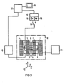
- 1 and 2 as well as 3 and 4 coils are identified with which a basic magnetic field Bo is generated, in which the body 5 of a patient to be examined is located when used for medical diagnosis.
- This is also associated with gradient coils, which are provided for generating independent, mutually perpendicular magnetic field gradients of the directions X, Y and Z as indicated in FIG. 6.
- gradient coils 7 and 8 are drawn in the figure, which together with a pair of opposite, similar gradient coils are used to generate the X gradient.
- the similar Y gradient coils not shown, lie parallel to the body 5 and above and below it, and those for the Z gradient field crosswise to its longitudinal axis at the head and foot ends.
- the arrangement also contains a coil 9 used to generate and record the nuclear magnetic resonance signals.
- the coils 1 to 9 delimited by a dash-dotted line 10 represent the actual examination instrument. It is operated by an electrical arrangement that has a power supply 11 for operating the coils 1 to 4 and a gradient power supply 12, on which the gradient coils 7 and 8 and the further gradient coils are included.
- the measuring coil 9 is connected via a signal amplifier 14 or a high-frequency transmitter 15 to a process computer 17, from which a screen device 18 is supplied to output the image.
- the components 14 and 15 form a high-frequency device 16 for signal generation and recording.
- a switch 19 enables switching from transmit to receive mode.
- FIG. 4 shows the echo signals occurring in the pulse sequence according to the invention in the event that a ⁇ 90 ° pulse is used as the fourth high-frequency pulse. Behind the ⁇ 180 ° pulse, the spin echo 40 with the amplitude, which is known from the conventional sequences, arises
- the 90 ° spin echo 41 has the maximum amplitude and provides information for a T 2 stressed image. After the time 4 ⁇ + ⁇ there is a stimulated echo with the maximum amplitude behind the fourth high-frequency pulse which contains information for a T i stressed image.
- the information obtained from the echoes 40, 41, 42 allow the T 1 and T 2 relaxation constants to be determined in a sequence. Because the additional information obtained is obtained together with the spin echo information in a sequence there is no need to extend the measuring time compared to the conventional spin echo method. The object set above is thus achieved by the four-pulse sequence according to the invention.
- step f) a pulse with a flip angle a is used instead of the pulse with flip angle ⁇ 90 ° , where
- partial readout pulse With the help of an expansion of the sequence by adding further partial readout pulses, additional information can be obtained for images with different T i emphasis.
Description
Die Erfindung betrifft ein Kernspinresonanzgerät zur Untersuchung eines Objektes mit Hilfe der kemmagnetischen Resonanz, mit Spulen zum Anlegen von magnetischen Grund- und Gradientenfeldern an das Untersuchungsobjekt und einer Hochfrequenzeinrichung, die das Untersuchungsobjekt mit einer Folge von Hochfrequenzpulsen bestrahlt und die von dem Untersuchungsobjekt abgestrahlten Kernresonanzsignale erfaßt.The invention relates to a nuclear magnetic resonance device for examining an object with the aid of the nuclear magnetic resonance, with coils for applying magnetic basic and gradient fields to the examination object and a high-frequency device which irradiates the examination object with a sequence of high-frequency pulses and detects the nuclear resonance signals emitted by the examination object.
Ein Gerät dieser Art ist in der deutschen Offenlegungsschrift 3 135 335 beschrieben. Dieses Gerät bietet die Möglichkeit, die magnetischen Kemmomente (Kemspins) eines Untersuchungsobjektes aus einer Vorzugsrichtung, die durch ein magnetisches Grundfeld festgelegt wird, mit Hilfe eines Hochfrequenzpulses auszulenken. Die dazu erforderliche Frequenz wo ist über die Gleichung wo = y.Bo durch das gyromagnetische Verhältnis y (charakteristische Größe für die betrachteten Atomkerne) und die magnetische Flußdichte Bo des Grundfeldes festgelegt. Nach der Einwirkung des Hochfrequenzfeldes strebt das System der Kemspins unter Aussendung von Kemresonanzsignalen wieder dem Grundzustand entgegen. Die Stärke des gemessenen Resonanzsignales ist proportional zur Anzahl der angeregten Kemspins und erlaubt somit Rückschluß auf die Spindichte des Untersuchungsobjektes.A device of this type is described in German Offenlegungsschrift 3 135 335. This device offers the possibility of deflecting the magnetic clamping moments (Kemspins) of an examination object from a preferred direction, which is determined by a basic magnetic field, with the aid of a high-frequency pulse. The frequency wo required for this is determined via the equation wo = y.Bo by the gyromagnetic ratio y (characteristic size for the atomic nuclei under consideration) and the magnetic flux density Bo of the basic field. After exposure to the high-frequency field, the system of the Kemspins strives to return to the ground state by sending out nuclear resonance signals. The strength of the measured resonance signal is proportional to the number of excited nuclear spins and thus allows conclusions to be drawn about the spin density of the examination object.
Liegen die Atomkerne, deren Resonanz man beobachtet, in verschiedenen chemischen Bindungszuständen vor, so ergeben sich aufgrund der unterschiedlichen lokalen Magnetfelder am Ort dieser Kerne auch unterschiedliche Resonanzfrequenzen. Die Intensitätsverhältnisse der zugehörigen Resonanzlinien zeigen in diesem Fall die relative Häufigkeit an, mit denen die untersuchten Kerne in den verschiedenen Bindungszuständen vorzufinden sind.If the atomic nuclei, the resonance of which is observed, are in different chemical bonding states, the different local magnetic fields at the location of these nuclei also result in different resonance frequencies. In this case, the intensity ratios of the associated resonance lines indicate the relative frequency with which the examined nuclei can be found in the various binding states.
Um ein Kernresonanzsignal nicht aus dem gesamten Untersuchungsobjekt, sondern nur aus einem bestimmten vorgegebenen Volumenbereich zu erhalten, werden lediglich die Kernspins in dem interessierenden Volumenbereich angeregt. Die Auswahl dieses Bereiches (in der Regel wählt man Ebenen) wird durch Überlagerung eines geeigneten magnetischen Gradientenfeldes über das Grundfeld erreicht. Das hierdurch resultierende inhomogene (z.B. in Z-Richtung linear ansteigende), magnetische Feld läßt bei Anwendung eines selektiven Hochfrequenzpulses die Anregung nur noch derjenigen Kerne zu, bei denen das magnetische Feld den für die obige Resonanzbedingung erforderlichen Wert besitzt (im Beispiel eine Schicht senkrecht zur Gradientenrichtung (Z-Richtung)). Um die Beiträge der verschiedenen Kerne zum Resonanzsignal innerhalb einer angeregten Ebene zu unterscheiden, schaltet man nach erfolgter Anregung das Gradientenfeld senkrecht zur Schicht aus und stattdessen einen Feldgradienten ein, dessen Richtung in der Schichtebene liegt (z.B. X-Richtung). Aufgrund der unterschiedlichen magnetischen Feldstärken präzedieren die Kerne der angeregten Schicht verschieden schnell und emittieren daher Resonanzsignale mit unterschiedlichen Frequenzen. Aus dem resultierenden empfangenen Signal S(t) können durch Fouriertransformationen (S(t)→ S(m))das Spektrum S(m) und damit die Frequenzanteile des Signales erhalten werden. Durch dieses Frequenzspektrum S(W) können also die verschiedenen Beiträge der Kerne zum Signal aufgrund ihrer Frequenz dem Ort ihrer Enstehung zugeordnet werden. Im Beispiel tragen alle Kerne in einem Streifen senkrecht zur X-Richtung mit derselben Frequenz zum Gesamtsignal bei, weil diese die gleiche Stärke des Magnetfeldes erfahren. Man erhält somit eine Projektion der Spindichte auf die Richtung des geschalteten Gradienten.In order to obtain a nuclear magnetic resonance signal not from the entire examination object, but rather only from a certain predetermined volume range, only the nuclear spins are excited in the volume range of interest. The selection of this area (usually one chooses planes) is achieved by superimposing a suitable magnetic gradient field over the basic field. The resulting inhomogeneous (e.g. linearly increasing in the Z-direction) magnetic field, when using a selective high-frequency pulse, only allows the excitation of those nuclei where the magnetic field has the value required for the above resonance condition (in the example a layer perpendicular to the Gradient direction (Z direction)). In order to distinguish the contributions of the different nuclei to the resonance signal within an excited plane, after the excitation has been carried out, the gradient field is switched off perpendicular to the slice and instead a field gradient whose direction lies in the slice plane (e.g. X direction) is switched on. Due to the different magnetic field strengths, the nuclei of the excited layer precess at different speeds and therefore emit resonance signals with different frequencies. The spectrum S (m) and thus the frequency components of the signal can be obtained from the resulting received signal S (t) by Fourier transformations (S (t) → S (m)). This frequency spectrum S ( W ) means that the different contributions of the nuclei to the signal can be assigned to the location of their origin based on their frequency. In the example, all the cores in a strip perpendicular to the X direction contribute to the overall signal with the same frequency because they experience the same strength of the magnetic field. A projection of the spin density onto the direction of the switched gradient is thus obtained.
Um ein Bild der angeregten Schicht konstruieren zu können, muß noch die Abhängigkeit des Resonanzsignales von der dritten Raumrichtung (im Beispiel Y-Richtung) ermittelt werden. Hierzu kann man
- a) die oben beschriebenen Messungen für viele Projektionsrichtungen (geeignete Kombinationen der X- und Y-Gradienten) wiederholen und aus den gewonnenen Meßdaten ein Spindichtebild der angeregten Schicht durch Rückprojektion konstruieren, oder ,
- b) die mit Hilfe bestimmter Kombinationen der X- und Y-Gradientenfelder aufgenommene zweidimensionale Meßmatrix einer zweidimensionalen Fouriertransformation unterziehen.
- a) repeat the measurements described above for many projection directions (suitable combinations of the X and Y gradients) and construct a spin density image of the excited layer from the obtained measurement data by back projection, or,
- b) subject the two-dimensional measurement matrix recorded with the aid of certain combinations of the X and Y gradient fields to a two-dimensional Fourier transformation.
Das von den untersuchten Kernen emittierte Kernresonanzsignal ist in der Amplitude nicht nur von der Spindichte des angeregten Bereiches, sondern unter anderem auch von der Spin-Gitter-Relaxation, Spin-Spin-Relaxation und den Feldinhomogenitäten abhängig. Man kann sich die Einflüsse der vorgenannten Parameter in einem vereinfachenden Kreiselmodell vorstellen, bei dem die Kernspins des Untersuchungsobjektes durch rotierende magnetische Momente (Kreisel) in einem magnetischen Grundfeld symbolisiert sind. Das Grundfeld soll dabei in Z-Richtung orientiert sein. In diesem Modell dreht das auf die Kemspins des Untersuchungsobjektes einwirkende magnetische Wechselfeld des Anregungspulses diese um einen bestimmten Winkel (Flipwinkel) aus der Z-Richtung heraus. Im Falle eines 90°-Pulses liegen alle Spins nach der Anregung parallel ausgerichtet innerhalb der X-Y-Ebene. Die sich anschließende Präzessionsbewegung der magnetischen Momente wird begleitet durch
- 1. die Spin-Spin-Relaxation (Wechselwirkung der Spins untereinander führt zu einer Abnahme der Magnetisierungskomponente in der X-Y-Ebene (Quermagnetisierung) mit der Zeitkonstanten T2 im Rahmen des oben beschriebenen Modells),
- 2. die Spin-Gitter-Relaxation (Wechselwirkung der Spins mit dem Gitter führt zur Rückkehr der Magnetisierung in den Ausgangszustand parallel zum Feld mit der Zeitkonstanten Ti),
- 3. Feldinhomogenitäten (bewirken ein Auseinanderlaufen der aus diesem Grunde mit verschiedenen Frequenzen präzedierenden Kreiselspins bezüglich der X-Y-Ebene).
- 1. the spin-spin relaxation (interaction of the spins with one another leads to a decrease in the magnetization component in the XY plane (transverse magnetization) with the time constant T 2 in the context of the model described above),
- 2. the spin-lattice relaxation (interaction of the spins with the lattice leads to the magnetization returning to the initial state parallel to the field with the time constant Ti),
- 3. Field inhomogeneities (cause the gyro spins, which therefore precess with different frequencies, to diverge with respect to the XY plane).
Im allgemeinen gilt für die Relaxationszeiten T1 und T2: T1 > T2. Die Amplitude des von den angeregten Kernen ausgesandten Signales (FID-Signal, free induction decay signal) ist unter anderem von der resultierenden Magnetisierungskomponente in der X-Y-Ebene bestimmt. Mehr als noch die Spin-Spin-Relaxation bewirkt das durch Feldinhomogenitäten bedingte Dephasieren der Spins die Abnahme dieser Komponente. Die durch beide Prozesse verursachte Abnahme der Quermagnetisierung wird oft mit der Zeitkonstanten Tz * beschrieben.The following generally applies to the relaxation times T 1 and T 2 : T 1 > T 2 . The amplitude of the signal emitted by the excited cores (FID signal, free induction decay signal) is determined, inter alia, by the resulting magnetization component in the XY plane. The dephasing of the spins due to field inhomogeneities causes the decrease of this component more than the spin-spin relaxation. The decrease in transverse magnetization caused by both processes is often described with the time constant T z * .
Da die durch Feldinhomogenitäten verursachte Dephasierung für jeden Ort ein fest vorgegebenes Zeitverhalten aufweist, kann dieser Prozeß durch geeignete Maßnahmen weitgehend umgekehrt werden (Refokussierung, z.B. durch einen ± 180°-Hochfrequenzpuls).Since the dephasing caused by field inhomogeneities has a predefined time behavior for each location, this process can be largely reversed by suitable measures (refocusing, e.g. by means of a ± 180 ° high-frequency pulse).
Man beobachtet ein Anwachsen der Amplitude des Resonanzsignales zu einem Maximum (Spin-Echo), bei der die durch Feldinhomogenität verursachte Dephasierung weitgehend kompensiert ist und schließlich wieder ein Abfallen der Amplitude mit der Zeitkonstanten T2 * aufgrund der erneuten Dephasierung. Dieser Fokussierungsprozeß ist wiederholt anwendbar (z.B. durch Folge von ± 180°-Pulsen) und führt zu weiteren Echos. Die zeitliche Abnahme der Stärke (Maximalamplituden) dieser Echos gibt daher Aufschluß über die Relaxationskonstante T2.An increase in the amplitude of the resonance signal to a maximum (spin echo) is observed, at which the dephasing caused by field inhomogeneity is largely compensated for, and finally a decrease in the amplitude with the time constant T 2 * due to the renewed dephasing. This focusing process can be used repeatedly (eg due to a sequence of ± 180 ° pulses) and leads to further echoes. The temporal decrease in the strength (maximum amplitudes) of these echoes therefore provides information about the relaxation constant T 2 .
Das sogenannte Spin-Echo-Verfahren benutzt eine Pulssequenz der beschriebenen Art (Fig. 1). Nachdem das FID-Signal 20 des ersten ± 90°-Pulses abgeklungen ist, wird durch den ersten ± 180°-Puls die Refokussierung eingeleitet. Nach der Zeit 2 τ (gerechnet vom Zeitpunkt des ersten ± 90°-Pulses) ist eine maximale Fokussierung erreicht (Maximalamplitude des ersten Spin-Echos 23). Die danach eintretende Dephasierung wird wegen eines weiteren ± 180°-Pulses wieder in eine Refokussierung umgekehrt. Durch die Refokussierung entsteht ein zweites Spin-Echo 25 zum Zeitpunkt 4 τ jedoch mit geringerer Maximalamplitude, da in der Zwischenzeit zufällige, zeitlich irreversible Spin-Spin-Wechselwirkungen eine Abnahme der Magnetisierung in der X-Y-Ebene zur Folge hatten. Nach einer Zeit TR beginnt die nächste Pulssequenz mit einem ± 90°-Puls.The so-called spin echo method uses a pulse sequence of the type described (FIG. 1). After the
Der zeitliche Verlauf des ersten Echosignales 23 S1 (t) wird durch das Kernspinresonanzgerät abgespeichert und stellt eine Zeile einer zweidimensionalen Meßmatrix dar. Entsprechend bildet das abgespeicherte Signal S2(t) des zweiten Echos 25 ebenfalls eine Zeile einer zweiten zweidimensionalen Meßmatrix. Mit jeder Sequenz werden bei entsprechender Wahl der Gradientenfelder andere Zeilen der beiden Meßmatrizen eingelesen. Im Falle der Bildrekonstruktion nach Verfahren b) wird dann jede der so erhaltenen vollständigen Meßmatrizen durch eine zweidimensionale Fouriertransformation in ein Ergebnisbild umgerechnet.The temporal course of the
Die Figur 2 zeigt eine Pulssequenz, wie sie beim "inversion recovery"-Verfahren benutzt wird. Diese Pulssequenz gleicht der Spin-Echo-Sequenz bis auf einen vorangestellten ± 180°-Puls. Dieser Puls bewirkt im Zusammenhang mit der Wahl einer bestimmten Zeitdifferenz eine stärkere Ti-Betonung der auf diese Weise aus den Spin-Echos 30 und 31 gewonnenen Bilder.FIG. 2 shows a pulse sequence as it is used in the "inversion recovery" method. This pulse sequence is similar to the spin-echo sequence except for a preceding ± 180 ° pulse. In conjunction with the selection of a specific time difference, this pulse brings about a stronger T i emphasis on the images obtained in this way from the
Unter bestimmten Bedingungen treten bei der Verwendung von Pulssequenzen mit drei oder mehr HF-Pulsen unter anderem sogenannte stimulierte Echos auf, die ihre Ursache im Falle einer Pulssequenz mit drei aufeinanderfolgenden 90°-Pulsen in der nach dem zweiten 90°-Puls vorhandenen Z-Komponente der Magnetisierung haben.Under certain conditions, when using pulse sequences with three or more RF pulses, so-called stimulated echoes occur, which are caused in the case of a pulse sequence with three successive 90 ° pulses in the Z component present after the second 90 ° pulse of magnetization.
Verfahren, bei denen stimulierte Echosignale erzeugt werden, sind erstmals in der Veröffentlichung von E.L. Hahn, "Phys. Rev." 80 (1950), Seite 580, beschrieben worden. Da die im stimulierten Echosignal enthaltenen Informationen ebenfalls für die bildgebende Kernspinresonanz ausgewertet werden können, ist es das Ziel der vorliegenden Erfindung, dieses stimulierte Echo innerhalb einer Pulssequenz zu erzeugen, und die Echoinformationen zum Beispiel zur Erstellung eines zusätzlichen Ti-betonten Bildes zu benutzen.Methods in which stimulated echo signals are generated are first described in the publication by E.L. Hahn, "Phys. Rev." 80 (1950), page 580. Since the information contained in the stimulated echo signal can also be evaluated for imaging magnetic resonance, the aim of the present invention is to generate this stimulated echo within a pulse sequence and to use the echo information, for example, to create an additional Ti-emphasized image.
Da in der MR-Bildgebung die Spindichte p die Relaxationszeiten T1 und T2 wichtige Parameter bei der Gewebecharakterisierung sind, ist man bestrebt, in kurzer Zeit möglichst viele Informationen über sie zu erhalten. Bisher konnten unterschiedliche Ti- und T2-betonte Bilder in einer Sequenz nicht gewonnen werden. Es bestand nur die Möglichkeit, in mehreren Meßsequenzen die gewünschten Informationen zu erhalten.Since in MR imaging the spin density p the relaxation times T 1 and T 2 are important parameters in tissue characterization, efforts are made to obtain as much information as possible about them in a short time. So far, different T i and T 2 stressed images could not be obtained in one sequence. It was only possible to obtain the desired information in several measuring sequences.
In der GB-A 2 126 731 sind Vorrichtungen und Verfahren zur Bildgebung mit Hilfe der kernmagnetischen Resonanz beschrieben. Dabei wird durch eine Pulssequenz 90°, r, 180°, «, 90° erreicht, daß die nötige Relaxationszeit zwischen zwei aufeinanderfolgen den Sequenzen erheblich reduziert wird, da die Kernspins durch den dritten Puls (90°) in einen Magnetisierungszustand versetzt werden, der demjenigen im Zustand des thermischen Gleichgewichtes sehr nahekommt.GB-
In dem Artikel "IEEE Transactions on Medical Imaging", Vol. MI-3, Nr. 1, März 1984, Seiten 41-46, ist eine Pulssequenz 90°, Ts1, 180°, TS2, 90°, 180°, Td beschrieben. Auch hier wird durch den 180°-Puls nahezu ein Rücksetzen in den thermischen Gleichgewichtszustand erreicht. Ausgelesen werden das FID-Signal und das 180°-Spin-Echo. Ein stimuliertes Echo kann mit dieser Sequenz nicht erzeugt werden.In the article "IEEE Transactions on Medical Imaging", Vol. MI-3, No. 1, March 1984, pages 41-46, a pulse sequence is 90 °, Ts 1 , 180 ° , T S2 , 90 ° , 180 ° , T d described. Here, too, the 180 ° pulse almost returns to the thermal equilibrium state. The FID signal and the 180 ° spin echo are read out. A stimulated echo cannot be generated with this sequence.
Der Erfindung liegt die Aufgabe zugrunde, ohne Verlängerung der Meßzeit in einer Meßsequenz neben den Informationen für ein herkömmliches Spin-Echo-Bild auch Informationen für ein Ti-betontes Bild und ein T2-betontes Spin-Echo-Bild zu erhalten.The object of the invention is to obtain, in addition to the information for a conventional spin-echo image, information for a Ti-emphasized image and a T 2 -accentuated spin-echo image in a measurement sequence without extending the measurement time.
Diese Aufgabe ist erfindungsgemäß dadurch gelöst, daß die Hochfrequenzeinrichtung (9 und 16) so ausgebildet ist, daß die von ihr erzeugten Hochfrequenzpulse und die von den Hochfrequenzpulsen erzeugten Echos innerhalb einer Sequenz in folgender zeitlicher Abfolge auftreten:
- a) Hochfrequenzpuls mit einem Flipwinkel von etwa ± 90° zum Zeitpunkt 0,
- b) Hochfrequenzpuls mit einem Flipwinkel von etwa ± 180° zum Zeitpunkte,
- c) ± 180°-Spin-
Echo 40zum Zeitpunkt 2 τ, - d) Hochfrequenzpuls mit einem Flipwinkel von etwa ± 90°
zum Zeitpunkt 3 τ, - e) ± 90•-Spin-
Echo 41 zum Zeitpunkt 4 τ, - f) Hochfrequenzpuls mit einem Flipwinkel von etwa τ 90° zu einem Zeitpunkt 3 τ + Δ, und
- g) stimuliertes Echo (42) zum Zeitpunkt 4 τ + Δ.
- a) high-frequency pulse with a flip angle of approximately ± 90 ° at time 0,
- b) high-frequency pulse with a flip angle of approximately ± 180 ° at the time,
- c) ± 180 °
spin echo 40 attime 2 τ, - d) high-frequency pulse with a flip angle of approximately ± 90 ° at
time 3 τ, - e) ± 90 • spin
echo 41 at time 4 τ, - f) high-frequency pulse with a flip angle of approximately τ 90 ° at a
time 3 τ + Δ, and - g) stimulated echo (42) at time 4 τ + Δ.
Diese Pulsfolge ermöglicht die Aufnahme von drei Bildern mit jeweils unterschiedlichem Informationsgehalt. Es handelt sich dabei um das aus den herkömmlichen Sequenzen bekannte Spin-Echo-Bild, ein T2-betontes Spin-Echo-Bild und ein Ti-betontes Bild (aus dem stimulierten Echo.)This pulse sequence enables three images to be recorded, each with a different information content. These are the spin-echo image known from the conventional sequences, a T 2 -accented spin-echo image and a Ti-emphasized image (from the stimulated echo.)
Die Erfindung ist nachfolgend anhand der Figuren 3 und 4 näher erläutert: Es zeigen:
- Fig. 3 das Blockschaltbild der wesentlichen Teile eines Kernspinresonanzgerätes, und
- Fig. 4 eine Pulssequenz gemäß der Erfindung.
- Fig. 3 shows the block diagram of the essential parts of a magnetic resonance apparatus, and
- Fig. 4 shows a pulse sequence according to the invention.
In der Figur 3 sind mit 1 und 2 sowie 3 und 4 Spulen gekennzeichnet, mit welchen ein magnetisches Grundfeld Bo erzeugt wird, in welchem sich bei Anwendung zur medizinischen Diagnostik der zu untersuchende Körper 5 eines Patienten befindet. Diesem sind außerdem Gradientenspulen zugeordnet, die zur Erzeugung unabhängiger, zueinander senkrechter Magnetfeldgradienten der Richtungen X, Y und Z gemäß der Andeutung in 6 vorgesehen sind. In der Figur sind der Übersichtlichkeit halber nur Gradientenspulen 7 und 8 gezeichnet, die zusammen mit einem Paar gegenüberliegender, gleichartiger Gradientenspulen zur Erzeugung des X-Gradienten dienen. Die gleichartigen, nicht gezeichneten Y-Gradientenspulen liegen parallel zum Körper 5 und oberhalb sowie unterhalb von ihm und die für das Z-Gradientenfeld quer zu seiner Längsachse am Kopf- und am Fußende. Die Anordnung enthält außerdem noch eine zur Erzeugung und Aufnahme der Kernresonanzsignale dienende Spule 9.In FIG. 3, 1 and 2 as well as 3 and 4 coils are identified with which a basic magnetic field Bo is generated, in which the
Die von einer strichpunktierten Linie 10 umgrenzten Spulen 1 bis 9 stellen das eigentliche Untersuchungsinstrument dar. Es wird von einer elektrischen Anordnung aus betrieben, die ein Netzgerät 11 zum Betrieb der Spulen 1 bis 4 sowie eine Gradientenstromversorgung 12, an welcher die Gradientenspulen 7 und 8 sowie die weiteren Gradientenspulen liegen, umfaßt. Die Meßspule 9 liegt über einen Signalverstärker 14 bzw. einen Hochfrequenzsender 15 an einem Prozeßrechner 17, von dem aus zur Ausgabe der Abbildung ein Bildschirmgerät 18 versorgt wird. Die Komponenten 14 und 15 bilden eine Hochfrequenzeinrichtung 16 zur Signalerzeugung und -aufnahme. Ein Umschalter 19 ermöglicht das Umschalten von Sende- auf Empfangsbetrieb.The coils 1 to 9 delimited by a dash-dotted
Die Figur 4 zeigt die bei der erfindungsgemäßen Pulssequenz auftretenden Echosignale für den Fall, daß als vierter Hochfrequenzpuls ein ± 90°-Puls verwendet wird. Hinter dem ± 180°-Puls entsteht das von den herkömmlichen Sequenzen bekannte Spinecho 40 mit der Amplitude
Das 90°-Spinecho 41 besitzt die Maximalamplitude![]()
![]()
![]()
![]()
Eine sinnvolle Weiterentwicklung der beschriebenen Pulssequenz ergibt sich beispielsweise durch Anfügung einer Serie von ± 180°-Pulsen, die weitere Informationen für T2-betonte Bilder liefern kann.A useful further development of the pulse sequence described results, for example, by adding a series of ± 180 ° pulses, which can provide further information for T 2 -accentuated images.
Verwendet man in Schritt f) anstatt des Pulses mit Flipwinkel ± 90° einen Puls mit einem Flipwinkel a, wobei |α| kleiner 90° ist, so wird nach diesem Puls nur ein Bruchteil des stimulierten Echossignales ausgelesen (Teilauslesepuls). Mit Hilfe einer Erweiterung der Sequenz durch Anfügung weiterer Teilauslesepulse lassen sich wiederum zusätzliche Informationen für Bilder mit unterschiedlicher Ti-Betonung gewinnen.If in step f) a pulse with a flip angle a is used instead of the pulse with flip angle ± 90 ° , where | α | is less than 90 ° , only a fraction of the stimulated echo signal is read out after this pulse (partial readout pulse). With the help of an expansion of the sequence by adding further partial readout pulses, additional information can be obtained for images with different T i emphasis.
Schließlich lassen sich durch Kombination aller durch die erfindungsgemäße Sequenz gewonnenen Informationen zusätzliche Bilder erzeugen.Finally, additional images can be generated by combining all the information obtained by the sequence according to the invention.
Claims (2)
Applications Claiming Priority (2)
| Application Number | Priority Date | Filing Date | Title |
|---|---|---|---|
| DE3514530 | 1985-04-22 | ||
| DE19853514530 DE3514530A1 (en) | 1985-04-22 | 1985-04-22 | NUCLEAR MISSION MACHINE |
Publications (2)
| Publication Number | Publication Date |
|---|---|
| EP0199202A1 EP0199202A1 (en) | 1986-10-29 |
| EP0199202B1 true EP0199202B1 (en) | 1989-10-18 |
Family
ID=6268831
Family Applications (1)
| Application Number | Title | Priority Date | Filing Date |
|---|---|---|---|
| EP86104942A Expired EP0199202B1 (en) | 1985-04-22 | 1986-04-10 | Nuclear spin resonance device |
Country Status (4)
| Country | Link |
|---|---|
| US (1) | US4684892A (en) |
| EP (1) | EP0199202B1 (en) |
| JP (1) | JPS61177610U (en) |
| DE (2) | DE3514530A1 (en) |
Families Citing this family (11)
| Publication number | Priority date | Publication date | Assignee | Title |
|---|---|---|---|---|
| IL79076A (en) * | 1986-06-10 | 1989-10-31 | Elscint Ltd | Restricted volume imaging |
| US4884029A (en) * | 1986-08-15 | 1989-11-28 | Picker International, Inc. | Quick imaging scheme utilizing differently phase encoded primary and stimulated echoes |
| US5055787A (en) * | 1986-08-27 | 1991-10-08 | Schlumberger Technology Corporation | Borehole measurement of NMR characteristics of earth formations |
| FR2613076B1 (en) * | 1987-03-25 | 1990-05-18 | Thomson Cgr | METHOD OF RAPID IMAGING BY NUCLEAR MAGNETIC RESONANCE |
| JPH0620446B2 (en) * | 1988-03-14 | 1994-03-23 | 株式会社日立メディコ | Coronary imager |
| NL8801731A (en) * | 1988-07-08 | 1990-02-01 | Philips Nv | METHOD AND NUCLEAR SPIN RESONANCE DEVICE FOR QUICK DETERMINATION OF THE CROSS RELAXATION TIME CONSTANT T2. |
| GB2517654B (en) * | 1989-06-21 | 2015-07-22 | Marconi Uk Intellectual Prop | Inspection Apparatus |
| US5655531A (en) * | 1995-05-15 | 1997-08-12 | The Board Of Trustees Of The Leland Stanford Junior University | MRI method and apparatus for selective image suppression of material based on T1 and T2 relation times |
| USRE45725E1 (en) | 2000-12-21 | 2015-10-06 | University Of Virginia Patent Foundation | Method and apparatus for spin-echo-train MR imaging using prescribed signal evolutions |
| USRE47178E1 (en) | 2000-12-21 | 2018-12-25 | University Of Virginia Patent Foundation | Method and apparatus for spin-echo-train MR imaging using prescribed signal evolutions |
| JP2003038456A (en) * | 2001-07-10 | 2003-02-12 | Ge Medical Systems Global Technology Co Llc | Spin excitation method, magnetic resonance photographing method and magnetic resonance photographing device |
Family Cites Families (12)
| Publication number | Priority date | Publication date | Assignee | Title |
|---|---|---|---|---|
| US4238735A (en) * | 1979-02-21 | 1980-12-09 | Varian Associates, Inc. | Indirect detection of nuclear spins of low gyromagentic ratio coupled to spins of high gyromagnetic ratio |
| DE3135335A1 (en) * | 1981-09-07 | 1983-08-18 | Siemens AG, 1000 Berlin und 8000 München | CORE SPIN TOMOGRAPHY METHOD |
| JPS5946546A (en) * | 1982-09-09 | 1984-03-15 | Yokogawa Hokushin Electric Corp | Inspection method and apparatus by nuclear magnetic resonator |
| FI67449C (en) * | 1982-12-17 | 1985-03-11 | Instrumentarium Oy | EXTENSION OF THE STRUCTURE OF THE EQUIPMENT |
| US4549140A (en) * | 1983-06-03 | 1985-10-22 | General Electric Company | Method utilizing combined, interleaved pulse sequences for reducing motion artifacts in computed T1,T2 and M0 NMR imaging |
| US4549139A (en) * | 1983-06-03 | 1985-10-22 | General Electric Company | Method of accurate and rapid NMR imaging of computed T1 and spin density |
| JPS59231438A (en) * | 1983-06-15 | 1984-12-26 | Yokogawa Hokushin Electric Corp | Inspection method and apparatus by nuclear magnetic resonance |
| JPS6022758A (en) * | 1983-07-18 | 1985-02-05 | Olympus Optical Co Ltd | Magnetic tape driver |
| GB2148013B (en) * | 1983-10-12 | 1988-02-03 | Yokogawa Electric Corp | Nuclear magnetic resonance imaging |
| US4570119A (en) * | 1983-11-15 | 1986-02-11 | General Electric Company | Method for visualization of in-plane fluid flow by proton NMR imaging |
| US4628626A (en) * | 1984-07-13 | 1986-12-16 | Brandt Raymond W | Safety mechanism for firearms |
| US4586709A (en) * | 1984-08-23 | 1986-05-06 | Godinet Wayne P | Cup stacking game apparatus |
-
1985
- 1985-04-22 DE DE19853514530 patent/DE3514530A1/en not_active Withdrawn
-
1986
- 1986-03-20 US US06/841,952 patent/US4684892A/en not_active Expired - Fee Related
- 1986-04-10 EP EP86104942A patent/EP0199202B1/en not_active Expired
- 1986-04-10 DE DE8686104942T patent/DE3666512D1/en not_active Expired
- 1986-04-18 JP JP1986058682U patent/JPS61177610U/ja active Pending
Also Published As
| Publication number | Publication date |
|---|---|
| JPS61177610U (en) | 1986-11-06 |
| US4684892A (en) | 1987-08-04 |
| DE3666512D1 (en) | 1989-11-23 |
| DE3514530A1 (en) | 1986-10-23 |
| EP0199202A1 (en) | 1986-10-29 |
Similar Documents
| Publication | Publication Date | Title |
|---|---|---|
| EP0074022B1 (en) | Apparatus for nuclear spin tomography | |
| EP0213436B1 (en) | Operating method of a nuclear magnetic resonance apparatus | |
| EP0184840B1 (en) | Arrangement for the spatially resolved inspection of a sample by means of magnetic resonance of spin moments | |
| DE3504734C2 (en) | Method and device for recording spin resonance data | |
| DE102008014060B4 (en) | Method for determining a phase position of a magnetization and magnetic resonance system | |
| EP0344518B1 (en) | Pulse sequences in nuclear spin tomography for producing images with differing T2 contrasts | |
| DE102008032155B4 (en) | Method for generating an excitation in an examination subject and a magnetic resonance system | |
| DE3437509C2 (en) | ||
| EP0199202B1 (en) | Nuclear spin resonance device | |
| EP0304984B1 (en) | Volume-selected spectral analysis by means of refocusing echoes | |
| EP0288861B1 (en) | Nuclear magnetic resonance imaging apparatus | |
| DE19814677B4 (en) | Correction of a deterioration of an axial-image signal caused by Maxwell terms | |
| DE4024161A1 (en) | PULSE SEQUENCE FOR QUICK DETERMINATION OF IMAGES OF FAT AND WATER DISTRIBUTION IN AN EXAMINATION OBJECT BY MEANS OF THE CORE MAGNETIC RESONANCE | |
| DE102014213413B4 (en) | Dynamic field detection in an MRI | |
| EP0425611B1 (en) | A process for recording spin resonance spectra and displaying spin resonance | |
| EP0422170B1 (en) | A process for recording spin resonance spectra | |
| DE3908392C2 (en) | ||
| DE3807130C2 (en) | Magnetic resonance imaging method | |
| DE102005049587B4 (en) | Method for operating a magnetic resonance system and magnetic resonance system | |
| EP0369538B1 (en) | Nuclear spin tomography method for determining the nuclear magnetization in a number of parallel slices | |
| EP0422172B1 (en) | Process for recording nuclear-resonance spectra | |
| EP0278254B1 (en) | Apparatus for determining nuclear magnetic resonance spectra from spatially selectable regions of an object under examination | |
| DE10219766A1 (en) | Method for the automatic measurement of acoustic resonances of a magnetic resonance tomography device | |
| WO2001048500A2 (en) | Imaging method and a device for processing image data | |
| DE19962476B4 (en) | Process for imaging examination of a sample using a recording sequence and rearrangement of echo signals |
Legal Events
| Date | Code | Title | Description |
|---|---|---|---|
| PUAI | Public reference made under article 153(3) epc to a published international application that has entered the european phase |
Free format text: ORIGINAL CODE: 0009012 |
|
| AK | Designated contracting states |
Kind code of ref document: A1 Designated state(s): DE FR GB NL |
|
| 17P | Request for examination filed |
Effective date: 19870424 |
|
| 17Q | First examination report despatched |
Effective date: 19880729 |
|
| GRAA | (expected) grant |
Free format text: ORIGINAL CODE: 0009210 |
|
| AK | Designated contracting states |
Kind code of ref document: B1 Designated state(s): DE FR GB NL |
|
| PG25 | Lapsed in a contracting state [announced via postgrant information from national office to epo] |
Ref country code: NL Effective date: 19891018 |
|
| REF | Corresponds to: |
Ref document number: 3666512 Country of ref document: DE Date of ref document: 19891123 |
|
| ET | Fr: translation filed | ||
| GBT | Gb: translation of ep patent filed (gb section 77(6)(a)/1977) | ||
| NLV1 | Nl: lapsed or annulled due to failure to fulfill the requirements of art. 29p and 29m of the patents act | ||
| PGFP | Annual fee paid to national office [announced via postgrant information from national office to epo] |
Ref country code: GB Payment date: 19900331 Year of fee payment: 5 |
|
| PLBE | No opposition filed within time limit |
Free format text: ORIGINAL CODE: 0009261 |
|
| STAA | Information on the status of an ep patent application or granted ep patent |
Free format text: STATUS: NO OPPOSITION FILED WITHIN TIME LIMIT |
|
| 26N | No opposition filed | ||
| PG25 | Lapsed in a contracting state [announced via postgrant information from national office to epo] |
Ref country code: FR Effective date: 19901228 |
|
| PG25 | Lapsed in a contracting state [announced via postgrant information from national office to epo] |
Ref country code: DE Effective date: 19910101 |
|
| REG | Reference to a national code |
Ref country code: FR Ref legal event code: ST |
|
| PG25 | Lapsed in a contracting state [announced via postgrant information from national office to epo] |
Ref country code: GB Effective date: 19910410 |
|
| GBPC | Gb: european patent ceased through non-payment of renewal fee |