EP0199064A2 - Green tire vulcanizing press - Google Patents
Green tire vulcanizing press Download PDFInfo
- Publication number
- EP0199064A2 EP0199064A2 EP86103410A EP86103410A EP0199064A2 EP 0199064 A2 EP0199064 A2 EP 0199064A2 EP 86103410 A EP86103410 A EP 86103410A EP 86103410 A EP86103410 A EP 86103410A EP 0199064 A2 EP0199064 A2 EP 0199064A2
- Authority
- EP
- European Patent Office
- Prior art keywords
- bladder
- tire
- well
- clamp ring
- lower die
- Prior art date
- Legal status (The legal status is an assumption and is not a legal conclusion. Google has not performed a legal analysis and makes no representation as to the accuracy of the status listed.)
- Granted
Links
- 238000007493 shaping process Methods 0.000 claims abstract description 25
- 230000033001 locomotion Effects 0.000 claims abstract description 24
- 239000011324 bead Substances 0.000 claims description 35
- 238000010438 heat treatment Methods 0.000 claims description 3
- 238000000034 method Methods 0.000 claims description 3
- 238000000926 separation method Methods 0.000 abstract description 4
- 230000007246 mechanism Effects 0.000 description 15
- 238000004073 vulcanization Methods 0.000 description 14
- 239000002131 composite material Substances 0.000 description 7
- 230000009956 central mechanism Effects 0.000 description 5
- 230000000694 effects Effects 0.000 description 3
- 230000008859 change Effects 0.000 description 2
- 238000003780 insertion Methods 0.000 description 2
- 230000037431 insertion Effects 0.000 description 2
- 239000007787 solid Substances 0.000 description 2
- 238000013459 approach Methods 0.000 description 1
- 238000013461 design Methods 0.000 description 1
- 230000008030 elimination Effects 0.000 description 1
- 238000003379 elimination reaction Methods 0.000 description 1
- 239000012530 fluid Substances 0.000 description 1
- 238000007306 functionalization reaction Methods 0.000 description 1
- 230000001771 impaired effect Effects 0.000 description 1
- 230000006872 improvement Effects 0.000 description 1
- 238000009434 installation Methods 0.000 description 1
- 238000012423 maintenance Methods 0.000 description 1
- 230000008569 process Effects 0.000 description 1
- 230000035939 shock Effects 0.000 description 1
- 230000001360 synchronised effect Effects 0.000 description 1
Images

Classifications
-
- B—PERFORMING OPERATIONS; TRANSPORTING
- B29—WORKING OF PLASTICS; WORKING OF SUBSTANCES IN A PLASTIC STATE IN GENERAL
- B29D—PRODUCING PARTICULAR ARTICLES FROM PLASTICS OR FROM SUBSTANCES IN A PLASTIC STATE
- B29D30/00—Producing pneumatic or solid tyres or parts thereof
- B29D30/06—Pneumatic tyres or parts thereof (e.g. produced by casting, moulding, compression moulding, injection moulding, centrifugal casting)
- B29D30/08—Building tyres
-
- B—PERFORMING OPERATIONS; TRANSPORTING
- B29—WORKING OF PLASTICS; WORKING OF SUBSTANCES IN A PLASTIC STATE IN GENERAL
- B29D—PRODUCING PARTICULAR ARTICLES FROM PLASTICS OR FROM SUBSTANCES IN A PLASTIC STATE
- B29D30/00—Producing pneumatic or solid tyres or parts thereof
- B29D30/06—Pneumatic tyres or parts thereof (e.g. produced by casting, moulding, compression moulding, injection moulding, centrifugal casting)
- B29D30/0601—Vulcanising tyres; Vulcanising presses for tyres
- B29D30/0645—Devices for inserting vulcanising cores, i.e. bladders, into the tyres; Closing the press in combination herewith
-
- B—PERFORMING OPERATIONS; TRANSPORTING
- B29—WORKING OF PLASTICS; WORKING OF SUBSTANCES IN A PLASTIC STATE IN GENERAL
- B29C—SHAPING OR JOINING OF PLASTICS; SHAPING OF MATERIAL IN A PLASTIC STATE, NOT OTHERWISE PROVIDED FOR; AFTER-TREATMENT OF THE SHAPED PRODUCTS, e.g. REPAIRING
- B29C35/00—Heating, cooling or curing, e.g. crosslinking or vulcanising; Apparatus therefor
- B29C35/02—Heating or curing, e.g. crosslinking or vulcanizing during moulding, e.g. in a mould
- B29C35/04—Heating or curing, e.g. crosslinking or vulcanizing during moulding, e.g. in a mould using liquids, gas or steam
-
- B—PERFORMING OPERATIONS; TRANSPORTING
- B29—WORKING OF PLASTICS; WORKING OF SUBSTANCES IN A PLASTIC STATE IN GENERAL
- B29D—PRODUCING PARTICULAR ARTICLES FROM PLASTICS OR FROM SUBSTANCES IN A PLASTIC STATE
- B29D30/00—Producing pneumatic or solid tyres or parts thereof
- B29D30/06—Pneumatic tyres or parts thereof (e.g. produced by casting, moulding, compression moulding, injection moulding, centrifugal casting)
- B29D30/0601—Vulcanising tyres; Vulcanising presses for tyres
-
- B—PERFORMING OPERATIONS; TRANSPORTING
- B29—WORKING OF PLASTICS; WORKING OF SUBSTANCES IN A PLASTIC STATE IN GENERAL
- B29C—SHAPING OR JOINING OF PLASTICS; SHAPING OF MATERIAL IN A PLASTIC STATE, NOT OTHERWISE PROVIDED FOR; AFTER-TREATMENT OF THE SHAPED PRODUCTS, e.g. REPAIRING
- B29C43/00—Compression moulding, i.e. applying external pressure to flow the moulding material; Apparatus therefor
- B29C43/02—Compression moulding, i.e. applying external pressure to flow the moulding material; Apparatus therefor of articles of definite length, i.e. discrete articles
- B29C43/10—Isostatic pressing, i.e. using non-rigid pressure-exerting members against rigid parts or dies
- B29C43/12—Isostatic pressing, i.e. using non-rigid pressure-exerting members against rigid parts or dies using bags surrounding the moulding material or using membranes contacting the moulding material
Definitions
- the present invention relates to a vulcanizing method of a tire press, especially a post-in-well type tire press, in which a green tire is loaded into a cavity formed by upper and lower dies capable of being opened and closed, then a shaping bladder is brought into close contact with the inner surface of the green tire, and the upper and lower dies are heated and a hot pressure medium is fed into the bladder to effect a vulcanizing press for the tire, a central mechanism of the tire press being so improved as to permit simplification of operations in the vulcanizing press as well as satisfactory structural simplification and functionalization required.
- a tire press which performs a vulcanizing press for a green tire by means of a lower die having a heat source, an upper die capable of being opened and closed relative to the lower die and having a heat source, a shaping bladder provided within a bladder well formed centrally in the lower die, and a hot pressure medium fed into the bladder, is well known as a so-called post-in-well type tire press, and the following prior art examples are existent.
- a bladder housing cylinder 6 is fixed centrally to a lower die 4; clamp portions 14, 15 at a central upper end of a cylindrical bag-like bladder 17 having a closed upper end and an open lower end are supported for vertical movement by a piston rod 13 of a hydraulic cylinder 10 disposed in a central position of the bladder housing cylinder 6; and clamp portions 19,20 of the bladder 17 are supported by the hydraulic cylinder 10 itself capable of being vertically moved by drive means 7 or 37, 41, the bladder 17 being raised into a green tire by the hydraulic cylinder 10 and drive means 7 or 37, 41 during vulcanization of a tire, while after completion of vulcanization, the upper and lower clamp portions 14, 15, 19, 20 of the bladder 17 are brought down into the bladder housing cylinder 16 by the hydraulic cylinder 10 and drive means 7 or 37, 41.
- the above parenthesized reference numerals are from the above patent publication, and the following parenthesized reference numerals are also from
- a lower bead ring 186 is provided at an upper end of a sleeve 185 which is fitted in a longitudinal bore member 180 vertically movably through actuators 188, 189, the longitudinal bore member 180 being fixed centrally to a lower die;
- a central post 200 is inserted centrally into the longitudinal bore member 180 vertically movably through a rod 252 of a piston cylinder assembly 251;
- an upper bead clamp 202 which holds an upper end of a shaping bladder 203 is attached to the post 200 so as to movable vertically together with the post 200;
- a lower bead clamp 201 which holds a lower end of the shaping bladder 203 is connected to a rod 220 of a piston cylinder assembly 219 so as to be vertically movable independently of the post 200, whereby, during vulcanization of a tire, the bladder 203 which is received in the sleeve 185 in
- a pipe 9 which holds a bead forming portion 8 is disposed vertically movable in a central part of a lower die half 3; lower end clamp portions 29, 31 of a blast hose 27 as a bladder are attached to a holding plate 32 fixed to an upper end of a pipe 34 which is inserted centrally into the pipe 9 vertically movably; and upper end clamp portions 28, 30 of the blast hose 27 are attached to an upper end of a rod 36 which is provided in the pipe 34 vertically movably through a piston 38 and which extends through the holding plate 32, whereby, during vulcanization of a tire, the pipe 9 is raised to receive the tire through its bead forming portion 8, then a pipe 15 disposed vertically movably on a central side of an upper die half 10 goes down and the tire is gripped from above and below by a bead forming portion 12 of the pipe 15, thereafter, the rod 36 raises the pipe 34 in a raised position, allowing the upper
- a well having a bead forming ring 3 formed at an upper end thereof is disposed in a central part of a lower segment die 11 so as to be movable vertically by means of a cylinder 13, and a clamp 7 having clamp rings 5, 6 for fixing upper and lower ends of a bellows 1 as a bladder is provided in the well vertically movably through an adjusting piston 8, whereby during vulcanization of a tire the bellows 1 is brought into contact with the inner surface of the tire set on the lower die half 11, with rise of the clamp 7, while after the vulcanization the upper die half 10 is opened and the well is raised to lift the tire from the lower die half 11, at the same time the clamp 7 is brought down into the well, thereby drawing out the bellows 1 from the inner surface of the tire and placing it in a twice-folded state within the well.
- the bladder 17 used therein is in the form of a cylindrical bag whose upper portion is closed, so not only the clamp portions 14, 15 at the central upper end of the bladder are required to have a special gripping structure different from the conventional clamp ring, but also this central upper end portion must have a larger wall thickness than the other portions.
- the sleeve 185 in contact with the well is movable verfically, thereby permitting the vulcanized tire to be lifted and removed from the lower die.
- the upper and lower bead clamps 202, 201 for the bladder 203 are provided vertically movably on the central post 200, there are required composite structure and operation for vertical movement as in the foregoing patent publication 37518/77.
- the upper and lower bead clamps 202, 201 are drawn close to each other and positioned in a central part of the tire, then the clamps 202, 201 are moved and expanded vertically in opposite directions.
- the tire press disclosed in Japanese Patent Laid-Open Publication No. 13241/67 is characterized by having a centering device 46, but as to its central mechanism, the pipe 9 in contact with the well is provided vertically movably, but the lower end clamp portions 29, 31 for the blast hose 27 in contact with the bladder are held by the vertically movable pipe 34 and the upper end clamp portions 28, 30 are attached to the rod 36 which is held by the pipe 34 vertically movably.
- a vertically movable structure of both upper and lower bladder clamps there are required complicated composite structure and troublesome composite operation like those in the foregoing two prior art tire presses.
- stowing the blast hose 27 in an extended state within the well is disadvantageous in that the lift stroke becomes larger and the device required below the lower die becomes larger in size.
- the well is made movable vertically and a single clamp 7 for fixing upper and lower ends of the bellows 1 as the bladder is provided in the well vertically movably, whereby a structural and operational simplification can be attained as compared with the foregoing three prior art tire presses.
- the bladder moves integrally in fixed relation to a single clamp 7 while the positions of the upper and lower clamp portions of the bladder remain unchanged, in other words, that the distance between the upper and lower ends of the bladder is unchanged in the shaping operation prior to vulcanization of a green tire, involve a problem in effecting a smooth loading of the bladder for the tire in conformity with changes in shape and size of the tire inner surface.
- the shaping function for obtaining a superior tire uniformity may not be fulfilled to a satisfactory extent.
- the bladder is stowed in a twice-folded state, there is a fear also in point of durability of the bladder.
- the stroke of the adjusting piston 8 for vertical movement of the clamp 7 becomes considerably large, making it difficult to obtain a compact equipment.
- a bladder well is provided vertically movably and an upper clamp ring of a shaping bladder is fixed while a lower clamp ring is made movable vertically, whereby the shaping of a green tire and the separation of the bladder and removal of the tire after vulcanizing press are performed through vertical movements of the lower clamp ring and the bladder well in a fixed state of the upper clamp ring.
- a green tire vulcanizing press including a lower die having a heat source, an upper die capable of being opened and closed relative to the lower die and having a heat source, a shaping bladder received in a bladder well disposed in a central part of the lower die, and a hot pressure medium supplied into the bladder
- the bladder well is made movable vertically and a lower bead ring is fixed to an upper end of the bladder well
- an upper clamp ring for the bladder is fixed to a center post extending upright through the center of the bladder well and through a buffer means at its lower end
- a lower clamp ring is held for vertical motion independently of the well, whereby the bladder well is brought down until the lower bead ring coincides with the lower die, whereupon a green tire is loaded onto the lower die past the bladder projecting upward from the well, then the bladder is brought into pressure contact with the inner surface of the tire by raising the lower clamp ring and supplying a hot pressure medium into the bladder, and after closing and clamping of the upper die relative to the lower
- a lower die 11 is fixed on a base 15 through a dome 16 and a hot platen 17, and a bladder well 5 is disposed vertically movable in a central portion of the lower die 11, the bladder well 5 having a lower bead ring 12 at an upper opening end thereof.
- a center post 1 is disposed through the center of the bladder well 5 and a lower end of the post 1 projecting downward from the bottom of the well 5 is supported by a support bracket 7 attached to the base 15, through a buffer member such as a cushion spring 6.
- an upper clamp ring 2 which holds an upper end of a shaping bladder 14, while a lower clamp ring 3 which holds a lower end of the bladder 14 is fitted on the post 3 vertically movably through a hub 18 and a stem 4.
- a drive source for this vertical movement there is used, for example, a hydraulic cylinder 9 attached to the bottom of the bladder well 5, and a piston rod 8 of the cylinder 9 is connected to the ring 3 side to move the ring up and down, thereby permitting shaping and vulcanizing press for a green tire 10.
- Fig. 1 in which the green tire 10 is set on the lower die 11 while its upper bead portion is held by a paddle 19 of a vertical loader or the like, ready for shaping.
- the bladder well 5 is in its lowermost position and the lower bead ring 12 is in engagement with a bead receiving portion of the lower die 11.
- the center post 1 is projecting fixedly in its solid line position and the upper clamp ring 2 is positioned above the well 5, while the lower clamp ring 3 is in a lowered position, whereby the bladder 14 is held in an extended state, with its upper portion side projecting from the well 5.
- a hot pressure medium such as steam is supplied into the bladder 14 through a hot pressure medium supply/discharge means comprising hot pressure medium supply/discharge holes 20 and pipes 21 connected to the holes 20 which holes and pipes are provided by utilizing the hub 18 of the lower clamp ring 3 in a known manner, whereby the bladder 14 is expanded toward the inner surface of the tire smoothly while its upper portion on the side of the upper clamp ring 2 on the center post 1 held in the fixed position is allowed to serve as a deformation fulcrum of the bladder, and the bladder comes closely into pressure contact with the inner surface of the tire by virtue of the hot pressure medium, and thus shaping for the tire is started.
- a buffer member such as the cushion spring 6 provided at the lower end of the center post 1.
- a stopper 13 is disposed on the bottom side of the bladder well 5 as shown in Figs. 1 and 2 whereby the stem 4 on the side of the lower clamp ring 3 can be locked in its raised position to keep the position of the ring 3 stationary.
- the upper die 25 is opened and retracted relative to the lower die, the supply of the hot pressure medium is stopped, the bladder well 5 is raised and the vulcanized tire 10 is pushed up and separated from the surface of the lower die 11 through the lower bead ring 12, as shown in Fig. 3.
- the lower clamp ring 3 is brought down, whereby the bladder 14 is separated from the inner surface of the tire 10 and drawn out extendedly into the well 5.
- Fig. 4 shows an uppermost position of the bladder well 5 and a lowermost position of the lower clamp ring 3.
- support arms 26 of a tire take-out device such as an unloader are moved up to positions under the tire 10 0 and support the tire in a known manner. Further, when the bladder 14 is completely stowed in the well 5, the vulcanized tire 10 is taken out from the press.
- the upper clamp ring 2 in the present invention is kept stationary and such various vertical movements for the upper clamp ring as in the prior art are not necessary at all, thus making it possible to omit all of lift device and members and lift motions for the upper clamp ring 2. It is apparent that only the bladder well 5 and the lower clamp ring 3 suffice as moving members. This greatly contributes to the omission of the device required for the movements of the bladder with the central mechanism as a nucleus, especially the omission of the motion mechanism, as well as the simplification of operation and improvement of the press cycle efficiency.
- the lower die 11 having a hot platen and the upper die 25 capable of being opened and closed relative to the lower die and having a heat source both used in the invention, there may be used various types employed in the conventional post-in-well type tire presses, the details of which are here omitted.
- the well 5 may be in the form of a cylinder having upper and lower openings if the stopper 13 can be provided in another position through a bracket or the like.
- the stopper 13 can be designed freely according to allowable space and position; for example, it may be pivoted about a pivot shaft so that it can be engaged with and disengaged from the lower end of the stem 4, or it may be moved forward and backward for such engagement and disengagement, though not shown.
- the bladder well 5 can be moved vertically by a mechanical means such as a knockout lever or link because the vertical movement of the well itself is a simple vertical linear motion, only reciprocating between the bottom and top positions, not requiring a stepwise stop, though not shown. It is advisable not to use a hydraulic cylinder. The adoption of such mechanical means is desirable for the simplification of mechanism and facilitation of maintenance.
- the center post 1 extending centrally through the bladder well 5 may be a solid post or a pipe, and as the buffer member provided at the lower end of the post there may be used an air cylinder in place of the cushion spring 6 used in the above embodiment.
- the shaping bladder 14 is cylindrical and it may be of the same structure as the conventional bladder.
- the upper and lower clamp rings 2 and 3 may have a known clamp structure.
- the hot pressure medium supply structure at the lower clamp ring 3 may also be the same as in the prior art as shown in the drawings.
- the upper clamp ring 2 may be fixed to the center post 1 threadedly or using a lock nut or by any other suitable means if only it can be kept stationary. In this case, there may be adopted an adjustable fixing structure which can change the fixing position as necessary.
- the mechanism for vertically moving the lower clamp ring 3 there may be adopted a mechanism comprising a screw shaft and a rotating nut with the shaft side being moved up and down, in place of the cylinder mechanism comprising the hydraulic cylinder 9 and the piston rod 8.
- the bladder well 5 having the lower bead ring 12 and the lower clamp ring 3 are in the lowermost positions, the tire 10 is placed on the lower bead ring 12 while being held by the paddle 19 of the tire loader, and fixed by the paddle 19, then the lower clamp ring 3 is raised and the hot pressure medium is introduced into the bladder 14.
- the hot pressure medium be supplied after the lower clamp ring 3 is raised up to the most suitable position. This is to prevent a too early supply of the hot pressure medium from causing the bladder 14 to expand and contact another member before contact with the inner surface of the tire.
- both upper and lower clamp rings which hold upper and lower ends of a bladder move up and down synchronously or relatively in an independent or combined fashion, so a lift mechanism for each of the upper and lower clamp rings as well as vertical motions are required.
- the use of hydraulic cylinders as drive sources requires their . installation in the limited space of inside or outside of the tire press well, thus leading to a complicated mechanism.
- a synchronous or relative vertical movement of both upper and lower clamp rings requires a composite operation always taking a positional relation of the two into consideration. This requirement is apt to cause troublesomeness of operation and difficulty of control.
- a center post is fixedly disposed upright centrally through the well and an upper clamp ring is fixed stationarily to an upper part of the center post.
- a lower clamp ring and the bladder well having a lower bead ring are disposed vertically movably, and the insertion of the bladder into the tire at the time of vulcanization as well as the separation of the bladder from the tire after vulcanization and the removal of the tire can be done by only the vertical movements of the lower clamp ring and the bladder well under a stationary state of the upper clamp ring.
- the lift mechanisms for the center post and upper clamp ring as well as their vertical motions can all be abolished, that is, the mechanisms required inside and outside the well can be simplified.
- the absence of a hydraulic cylinder mechanism in the well permits elimination of troubles such as leakage of hydraulic fluid and band influence of heat which troubles are attributable to the presence of a hydraulic cylinder mechanism in the well as in the prior art.
- a hydraulic cylinder mechanism in the well permits elimination of troubles such as leakage of hydraulic fluid and band influence of heat which troubles are attributable to the presence of a hydraulic cylinder mechanism in the well as in the prior art.
- the bladder well 5 and lower clamp ring 3 in the present invention there can be surely attained simplification of mechanism and that of operation process, thus resulting in that a large space is no longer necessary below the tire press and a compact machine design can be done easily.
- the lower clamp ring 3 is movable vertically, the bladder can be deformed for contact with the inner surface of a tire freely according to the size and shape of the tire.
- the shaping function for improving the tire uniformity is not likely to be impaired, and since the bladder moves relative to the upper clamp ring 2 which is kept stationary, it is possible to attain a proper positioning and an accurate motion control. Besides, the bladder can be stowed in an extended state within the well, without such an unnatural way of stowing as twice-folded, and so there is obtained a satisfactory durability of the bladder. And there is no fear of contact of the bladder with another member at the time of insertion of the bladder into a tire.
- the present invention contributes to the solution of the problems involved in the conventional post-in-well type tire press.
Landscapes
- Engineering & Computer Science (AREA)
- Mechanical Engineering (AREA)
- Physics & Mathematics (AREA)
- Health & Medical Sciences (AREA)
- Oral & Maxillofacial Surgery (AREA)
- Thermal Sciences (AREA)
- Moulds For Moulding Plastics Or The Like (AREA)
- Heating, Cooling, Or Curing Plastics Or The Like In General (AREA)
- Tyre Moulding (AREA)
Abstract
Description
- The present invention relates to a vulcanizing method of a tire press, especially a post-in-well type tire press, in which a green tire is loaded into a cavity formed by upper and lower dies capable of being opened and closed, then a shaping bladder is brought into close contact with the inner surface of the green tire, and the upper and lower dies are heated and a hot pressure medium is fed into the bladder to effect a vulcanizing press for the tire, a central mechanism of the tire press being so improved as to permit simplification of operations in the vulcanizing press as well as satisfactory structural simplification and functionalization required.
- A tire press which performs a vulcanizing press for a green tire by means of a lower die having a heat source, an upper die capable of being opened and closed relative to the lower die and having a heat source, a shaping bladder provided within a bladder well formed centrally in the lower die, and a hot pressure medium fed into the bladder, is well known as a so-called post-in-well type tire press, and the following prior art examples are existent.
- In the tire press disclosed in Japanese Patent Publication No. 37518/77, although details are as described in the published specification thereof, a
bladder housing cylinder 6 is fixed centrally to alower die 4;clamp portions 14, 15 at a central upper end of a cylindrical bag-like bladder 17 having a closed upper end and an open lower end are supported for vertical movement by apiston rod 13 of ahydraulic cylinder 10 disposed in a central position of thebladder housing cylinder 6; andclamp portions bladder 17 are supported by thehydraulic cylinder 10 itself capable of being vertically moved bydrive means 7 or 37, 41, thebladder 17 being raised into a green tire by thehydraulic cylinder 10 and drive means 7 or 37, 41 during vulcanization of a tire, while after completion of vulcanization, the upper andlower clamp portions bladder 17 are brought down into thebladder housing cylinder 16 by thehydraulic cylinder 10 and drive means 7 or 37, 41. (The above parenthesized reference numerals are from the above patent publication, and the following parenthesized reference numerals are also from the publications concerned.) - In the tire press disclosed in Japanese Patent Laid-Open Publication No. 148539/81, as a central mechanism 38 a lower bead ring 186 is provided at an upper end of a sleeve 185 which is fitted in a longitudinal bore member 180 vertically movably through actuators 188, 189, the longitudinal bore member 180 being fixed centrally to a lower die; a central post 200 is inserted centrally into the longitudinal bore member 180 vertically movably through a rod 252 of a piston cylinder assembly 251; an upper bead clamp 202 which holds an upper end of a shaping bladder 203 is attached to the post 200 so as to movable vertically together with the post 200; and a lower bead clamp 201 which holds a lower end of the shaping bladder 203 is connected to a rod 220 of a piston cylinder assembly 219 so as to be vertically movable independently of the post 200, whereby, during vulcanization of a tire, the bladder 203 which is received in the sleeve 185 in a twice-folded state of approach of the upper and lower bead clamps 202, 201 is positioned centrally in the tire which has been received by the sleeve 185 in a raised position and then brought down together with the sleeve, thereafter the upper and lower bead clamps 202, 201 close to each other are separated up and down, allowing them to come into contact with the inner surface of the tire, while after completion of vulcanization the sleeve 185 is raised to lift the tire from the lower die surface and at the same time the upper and lower bead clamps 202, 201 are moved toward each other and thereby separated from the inner surface of the tire, thus the bladder 203 is received in a twice-folded state in the sleeve 185 by the relative movement of the upper and lower bead clamps 202, 201 caused by rise of the sleeve 185.
- In the tire press disclosed in Japanese Patent Publication No. 13241/67, a
pipe 9 which holds abead forming portion 8 is disposed vertically movable in a central part of alower die half 3; lower end clamp portions 29, 31 of a blast hose 27 as a bladder are attached to a holding plate 32 fixed to an upper end of a pipe 34 which is inserted centrally into thepipe 9 vertically movably; and upper end clamp portions 28, 30 of the blast hose 27 are attached to an upper end of a rod 36 which is provided in the pipe 34 vertically movably through a piston 38 and which extends through the holding plate 32, whereby, during vulcanization of a tire, thepipe 9 is raised to receive the tire through itsbead forming portion 8, then a pipe 15 disposed vertically movably on a central side of anupper die half 10 goes down and the tire is gripped from above and below by abead forming portion 12 of the pipe 15, thereafter, the rod 36 raises the pipe 34 in a raised position, allowing the upper end clamp portions 28, 30 of the blast hose 27 at the upper end of the rod 36 to come into contact with thebead forming portion 12, and the pipe 34 is further raised, thereby allowing the blast hose 27 to be engaged with the inner surface of the tire through rise of the lower end clamp portions 29, 31 of the blast hose 27, then thepipes 15, 9, 34 are brought down synchronously to set the tire onto thelower die half 3, followed by closing with theupper die half 10, while after completion of vulcanization theupper die half 10 is opened and the rod 36 is raised, allowing the upper end clamp portions 28, 30 to rise at the same time, thereby drawing out the blast hose 27 upward from the inner surface of the tire, and the tire is raised from thelower die half 3 by rise of thebead forming portion 8 of thepipe 9, and the blast hose 27 in an extended state is received in thepipe 9 by means of the rod 36 which descends together with the pipe 34. - Further, in the tire press disclosed in Japanese Patent Laid-Open Publication No. 79282/73, a well having a
bead forming ring 3 formed at an upper end thereof is disposed in a central part of a lower segment die 11 so as to be movable vertically by means of acylinder 13, and aclamp 7 havingclamp rings piston 8, whereby during vulcanization of a tire the bellows 1 is brought into contact with the inner surface of the tire set on the lower die half 11, with rise of theclamp 7, while after the vulcanization theupper die half 10 is opened and the well is raised to lift the tire from the lower die half 11, at the same time theclamp 7 is brought down into the well, thereby drawing out the bellows 1 from the inner surface of the tire and placing it in a twice-folded state within the well. - The above are summaries of the prior art tire presses mainly about the respective central mechanisms as nuclei of vulcanization and the contents of bladder motions thereby performed. In all of these prior art tire presses, a well is fixed or made movable vertically and upper and lower clamp rings which hold upper and lower ends of a bladder received in a well are moved in a vertical direction relatively or synchronously to effect charge and discharge of the bladder with respect to the inner surface of the tire and also effect separation of the tire from the lower die.
- The above prior art tire presses involve the following problems. In the tire press disclosed in Japanese Patent Publication No. 37518177, the
bladder housing cylinder 6 or the bladder well is stationary, so in order to take out the vulcanized tire from the lower die it is necessary to provide mechanism and operation for opening a chuck 61 of an upper beam of the press, clamping an upper bead portion of the tire between the chuck 61 and a bead ring of anupper die 65 and then opening adome 6 and theupper die 65 upward. Besides, for relatively moving the central upperend clamp portions 14, 15 and lowerend clarnp portions bladder 17, two lift mechanisms are required which are thehydraulic cylinder 10 and the drive means 7 or 37, 41 for moving thecylinder 10 itself. Further, unlike the conventional cylindrical bladder, thebladder 17 used therein is in the form of a cylindrical bag whose upper portion is closed, so not only theclamp portions 14, 15 at the central upper end of the bladder are required to have a special gripping structure different from the conventional clamp ring, but also this central upper end portion must have a larger wall thickness than the other portions. As a whole, the mechanism and structure, including the composite structure and operation for vertical movement using thehydraulic cylinder 10 and drive means 7 or 37, 41. This and the troublesome of control using the composite operation are disadvantageous factors. In the tire press disclosed in Japanese Patent Laid-Open Publication No. 148539/81, the sleeve 185 in contact with the well is movable verfically, thereby permitting the vulcanized tire to be lifted and removed from the lower die. But, since the upper and lower bead clamps 202, 201 for the bladder 203 are provided vertically movably on the central post 200, there are required composite structure and operation for vertical movement as in the foregoing patent publication 37518/77. Particularly, in introducing the bladder 203 into contact with the inner surface of the tire, the upper and lower bead clamps 202, 201 are drawn close to each other and positioned in a central part of the tire, then the clamps 202, 201 are moved and expanded vertically in opposite directions. Therefore, an accurate control for those operations is extremefy complicated, and in separating the bladder 203 after vulcanizing from the inner surface of the tire, it is necessary to bring down the upper bead clamp 202 while raising the lower bead clamp 201. Besides, in shaping a green tire, the upper bead ring 202 is raised while lowering the lower bead ring 201, so in a chuck assembly 55 which holds the tire, it is necessary to bring it down in synchronism with the descent of the lower bead ring 201 during shaping. These composite operations are extremely troublesome and there is a disadvantage in point of more complicated structures of devices required. Further in both of the above prior art tire presses, the bladder is stowed in a twice-folded state, so there is a fear also in point of durability of the bladder. - The tire press disclosed in Japanese Patent Laid-Open Publication No. 13241/67 is characterized by having a centering device 46, but as to its central mechanism, the
pipe 9 in contact with the well is provided vertically movably, but the lower end clamp portions 29, 31 for the blast hose 27 in contact with the bladder are held by the vertically movable pipe 34 and the upper end clamp portions 28, 30 are attached to the rod 36 which is held by the pipe 34 vertically movably. Thus, due to a vertically movable structure of both upper and lower bladder clamps, there are required complicated composite structure and troublesome composite operation like those in the foregoing two prior art tire presses. Moreover, stowing the blast hose 27 in an extended state within the well is disadvantageous in that the lift stroke becomes larger and the device required below the lower die becomes larger in size. - In the tire press disclosed in Japanese Patent Laid-Open Publication No. 79282/73, the well is made movable vertically and a
single clamp 7 for fixing upper and lower ends of the bellows 1 as the bladder is provided in the well vertically movably, whereby a structural and operational simplification can be attained as compared with the foregoing three prior art tire presses. However, that the bladder moves integrally in fixed relation to asingle clamp 7 while the positions of the upper and lower clamp portions of the bladder remain unchanged, in other words, that the distance between the upper and lower ends of the bladder is unchanged in the shaping operation prior to vulcanization of a green tire, involve a problem in effecting a smooth loading of the bladder for the tire in conformity with changes in shape and size of the tire inner surface. Besides, the shaping function for obtaining a superior tire uniformity may not be fulfilled to a satisfactory extent. Further, since the bladder is stowed in a twice-folded state, there is a fear also in point of durability of the bladder. Additionally, the stroke of the adjustingpiston 8 for vertical movement of theclamp 7 becomes considerably large, making it difficult to obtain a compact equipment. - In the present invention, in order to overcome the above-mentioned problems of the conventional post-in-well type tire presses, a bladder well is provided vertically movably and an upper clamp ring of a shaping bladder is fixed while a lower clamp ring is made movable vertically, whereby the shaping of a green tire and the separation of the bladder and removal of the tire after vulcanizing press are performed through vertical movements of the lower clamp ring and the bladder well in a fixed state of the upper clamp ring. More particularly, in a green tire vulcanizing press including a lower die having a heat source, an upper die capable of being opened and closed relative to the lower die and having a heat source, a shaping bladder received in a bladder well disposed in a central part of the lower die, and a hot pressure medium supplied into the bladder, the bladder well is made movable vertically and a lower bead ring is fixed to an upper end of the bladder well, an upper clamp ring for the bladder is fixed to a center post extending upright through the center of the bladder well and through a buffer means at its lower end, and a lower clamp ring is held for vertical motion independently of the well, whereby the bladder well is brought down until the lower bead ring coincides with the lower die, whereupon a green tire is loaded onto the lower die past the bladder projecting upward from the well, then the bladder is brought into pressure contact with the inner surface of the tire by raising the lower clamp ring and supplying a hot pressure medium into the bladder, and after closing and clamping of the upper die relative to the lower die and completion of a vulcanizing press for the green tire conducted under continuous supply of the hot pressure medium and heating of the dies, the upper die is opened and the bladder well is raised to push up and remove the vulcanized tire from the lower die, and the lower clamp ring is brought down to withdraw and separate the bladder from the inner surface of the tire.
-
- Fig. 1 is a front view in longitudinal section of a principal portion in shaping operation according to an embodiment of the present invention;
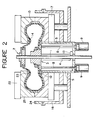
- Fig. 2 is a front view thereof in vulcanizing operation;
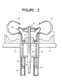
- Fig. 3 is a front view thereof showing a bladder as separated from a tire after vulcanization; and
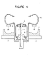
- Fig. 4 is a front view thereof showing the tire about to be taken out after vulcanization.
- A preferred embodiment of the present invention will be described in detail hereinunder with reference to Figs. 1 to 4.
- As shown in Fig. 1, a lower die 11 is fixed on a base 15 through a
dome 16 and ahot platen 17, and a bladder well 5 is disposed vertically movable in a central portion of the lower die 11, the bladder well 5 having alower bead ring 12 at an upper opening end thereof. A center post 1 is disposed through the center of the bladder well 5 and a lower end of the post 1 projecting downward from the bottom of thewell 5 is supported by asupport bracket 7 attached to the base 15, through a buffer member such as acushion spring 6. To an upper part of this fixed center post 1 is fixed anupper clamp ring 2 which holds an upper end of ashaping bladder 14, while alower clamp ring 3 which holds a lower end of thebladder 14 is fitted on thepost 3 vertically movably through ahub 18 and astem 4. As a drive source for this vertical movement there is used, for example, ahydraulic cylinder 9 attached to the bottom of the bladder well 5, and apiston rod 8 of thecylinder 9 is connected to thering 3 side to move the ring up and down, thereby permitting shaping and vulcanizing press for agreen tire 10. - More specifically, reference is here made to Fig. 1 in which the
green tire 10 is set on the lower die 11 while its upper bead portion is held by apaddle 19 of a vertical loader or the like, ready for shaping. The bladder well 5 is in its lowermost position and thelower bead ring 12 is in engagement with a bead receiving portion of the lower die 11. The center post 1 is projecting fixedly in its solid line position and theupper clamp ring 2 is positioned above thewell 5, while thelower clamp ring 3 is in a lowered position, whereby thebladder 14 is held in an extended state, with its upper portion side projecting from thewell 5. In this state, thepiston rod 8 of thehydraulic cylinder 9 is raised, thereby allowing thelower clamp ring 3 to rise from its solid position to its chain line position, and a hot pressure medium such as steam is supplied into thebladder 14 through a hot pressure medium supply/discharge means comprising hot pressure medium supply/discharge holes 20 andpipes 21 connected to theholes 20 which holes and pipes are provided by utilizing thehub 18 of thelower clamp ring 3 in a known manner, whereby thebladder 14 is expanded toward the inner surface of the tire smoothly while its upper portion on the side of theupper clamp ring 2 on the center post 1 held in the fixed position is allowed to serve as a deformation fulcrum of the bladder, and the bladder comes closely into pressure contact with the inner surface of the tire by virtue of the hot pressure medium, and thus shaping for the tire is started. Upon retraction of the tire loader, anupper die 25 having ahot platen 22, anupper bead ring 23 and adome 24 corresponding to thedome 16, as shown in Fig. 2, is closed and clamped relative to the lower die and a vulcanizing press for thetire 10 is performed continuously under heating of bothdies 11 and 25 and continuous supply of the hot pressure medium. At this time, an entire compressive shock induced by closing of theupper die 25 can be absorbed by the buffer member such as thecushion spring 6 provided at the lower end of the center post 1. Further, astopper 13 is disposed on the bottom side of the bladder well 5 as shown in Figs. 1 and 2 whereby thestem 4 on the side of thelower clamp ring 3 can be locked in its raised position to keep the position of thering 3 stationary. - After completion of the vulcanizing press work required, the
upper die 25 is opened and retracted relative to the lower die, the supply of the hot pressure medium is stopped, the bladder well 5 is raised and thevulcanized tire 10 is pushed up and separated from the surface of the lower die 11 through thelower bead ring 12, as shown in Fig. 3. At the same time, thelower clamp ring 3 is brought down, whereby thebladder 14 is separated from the inner surface of thetire 10 and drawn out extendedly into thewell 5. - Fig. 4 shows an uppermost position of the bladder well 5 and a lowermost position of the
lower clamp ring 3. In this state, supportarms 26 of a tire take-out device such as an unloader are moved up to positions under thetire 10 0 and support the tire in a known manner. Further, when thebladder 14 is completely stowed in thewell 5, thevulcanized tire 10 is taken out from the press. - During the series of operations from shaping through vulcanizing press up to taking out of tire described above, the
upper clamp ring 2 in the present invention is kept stationary and such various vertical movements for the upper clamp ring as in the prior art are not necessary at all, thus making it possible to omit all of lift device and members and lift motions for theupper clamp ring 2. It is apparent that only the bladder well 5 and thelower clamp ring 3 suffice as moving members. This greatly contributes to the omission of the device required for the movements of the bladder with the central mechanism as a nucleus, especially the omission of the motion mechanism, as well as the simplification of operation and improvement of the press cycle efficiency. - As the lower die 11 having a hot platen and the
upper die 25 capable of being opened and closed relative to the lower die and having a heat source, both used in the invention, there may be used various types employed in the conventional post-in-well type tire presses, the details of which are here omitted. - Although the bladder well 5 disposed vertically movably in a central portion of the lower die 11 is provided with a
bottom portion 5a in the embodiment illustrated, such bottom portion is not always necessary. Thewell 5 may be in the form of a cylinder having upper and lower openings if thestopper 13 can be provided in another position through a bracket or the like. Thestopper 13 can be designed freely according to allowable space and position; for example, it may be pivoted about a pivot shaft so that it can be engaged with and disengaged from the lower end of thestem 4, or it may be moved forward and backward for such engagement and disengagement, though not shown. The bladder well 5 can be moved vertically by a mechanical means such as a knockout lever or link because the vertical movement of the well itself is a simple vertical linear motion, only reciprocating between the bottom and top positions, not requiring a stepwise stop, though not shown. It is advisable not to use a hydraulic cylinder. The adoption of such mechanical means is desirable for the simplification of mechanism and facilitation of maintenance. The center post 1 extending centrally through the bladder well 5 may be a solid post or a pipe, and as the buffer member provided at the lower end of the post there may be used an air cylinder in place of thecushion spring 6 used in the above embodiment. In the case of using thespring 6, the spring is disposed resiliently between a flange 27 and thebracket 7 and an end portion having a nut 28 is loosely inserted through thebracket 7, as illustrated in the drawings. The shapingbladder 14 is cylindrical and it may be of the same structure as the conventional bladder. The upper and lower clamp rings 2 and 3 may have a known clamp structure. The hot pressure medium supply structure at thelower clamp ring 3 may also be the same as in the prior art as shown in the drawings. Theupper clamp ring 2 may be fixed to the center post 1 threadedly or using a lock nut or by any other suitable means if only it can be kept stationary. In this case, there may be adopted an adjustable fixing structure which can change the fixing position as necessary. As the mechanism for vertically moving thelower clamp ring 3 there may be adopted a mechanism comprising a screw shaft and a rotating nut with the shaft side being moved up and down, in place of the cylinder mechanism comprising thehydraulic cylinder 9 and thepiston rod 8. In starting shaping for thegreen tire 10 as shown in Fig. 1 in the embodiment illustrated, when the bladder well 5 having thelower bead ring 12 and thelower clamp ring 3 are in the lowermost positions, thetire 10 is placed on thelower bead ring 12 while being held by thepaddle 19 of the tire loader, and fixed by thepaddle 19, then thelower clamp ring 3 is raised and the hot pressure medium is introduced into thebladder 14. In actual operation, it is preferble that the hot pressure medium be supplied after thelower clamp ring 3 is raised up to the most suitable position. This is to prevent a too early supply of the hot pressure medium from causing thebladder 14 to expand and contact another member before contact with the inner surface of the tire. - According to the present invention there are obtained the following advantages. In the prior art, both upper and lower clamp rings which hold upper and lower ends of a bladder move up and down synchronously or relatively in an independent or combined fashion, so a lift mechanism for each of the upper and lower clamp rings as well as vertical motions are required. For example, the use of hydraulic cylinders as drive sources requires their . installation in the limited space of inside or outside of the tire press well, thus leading to a complicated mechanism. Particularly, a synchronous or relative vertical movement of both upper and lower clamp rings requires a composite operation always taking a positional relation of the two into consideration. This requirement is apt to cause troublesomeness of operation and difficulty of control. Further, it is necessary that the bladder be stowed in a twice-folded state in order to shorten the stroke. Besides, the movement and change in an extended state are disadvantageous in that a longer stroke results. On the other hand, in the present invention, a center post is fixedly disposed upright centrally through the well and an upper clamp ring is fixed stationarily to an upper part of the center post. Further, a lower clamp ring and the bladder well having a lower bead ring are disposed vertically movably, and the insertion of the bladder into the tire at the time of vulcanization as well as the separation of the bladder from the tire after vulcanization and the removal of the tire can be done by only the vertical movements of the lower clamp ring and the bladder well under a stationary state of the upper clamp ring. As a result, the lift mechanisms for the center post and upper clamp ring as well as their vertical motions can all be abolished, that is, the mechanisms required inside and outside the well can be simplified. Particularly, the absence of a hydraulic cylinder mechanism in the well permits elimination of troubles such as leakage of hydraulic fluid and band influence of heat which troubles are attributable to the presence of a hydraulic cylinder mechanism in the well as in the prior art. Because of only the vertical movements of the bladder well 5 and
lower clamp ring 3 in the present invention, there can be surely attained simplification of mechanism and that of operation process, thus resulting in that a large space is no longer necessary below the tire press and a compact machine design can be done easily. Also in the shaping function, since thelower clamp ring 3 is movable vertically, the bladder can be deformed for contact with the inner surface of a tire freely according to the size and shape of the tire. The shaping function for improving the tire uniformity is not likely to be impaired, and since the bladder moves relative to theupper clamp ring 2 which is kept stationary, it is possible to attain a proper positioning and an accurate motion control. Besides, the bladder can be stowed in an extended state within the well, without such an unnatural way of stowing as twice-folded, and so there is obtained a satisfactory durability of the bladder. And there is no fear of contact of the bladder with another member at the time of insertion of the bladder into a tire. Thus, as a new vulcanizing means in tire press, the present invention contributes to the solution of the problems involved in the conventional post-in-well type tire press.
Claims (1)
- A vulcanizing method in a green tire vulcanizing press including a lower die having a heat source, an upper die capable of being opened and closed relative to the lower die and having a heat source, a shaping bladder received in a bladder well disposed in a central part of the lower die, and a hot pressure medium supplied into the bladder, characterized in that said bladder well is made movable vertically and a lower bead ring is fixed to an upper end of the bladder well; an upper clamp ring for the bladder is fixed to a center post extending upright through the center of the bladder well and through a buffer means at its lower end; and a lower clamp ring is held for vertical movement independently of the well, whereby said bladder well is broughtedown until the lower bead ring coincides with the lower die, whereupon a green tire is loaded onto the lower die past the bladder projecting upward from the well, then the bladder is brought into pressure contact with the inner surface of the tire by raising the lower clamp ring and supplying a hot pressure medium into the bladder, and after closing and clamping of the upper die relative to the lower die and completion of a vulcanizing press for the green tire conducted under continuous supply of the hot pressure medium and heating of the dies, the upper die is opened and the bladder well is raised to push up and remove the vulcanized tire from the lower die, and the lower clamp ring is brought down to withdraw and separate the bladder from the inner surface of the tire.
Applications Claiming Priority (2)
| Application Number | Priority Date | Filing Date | Title |
|---|---|---|---|
| JP62642/85 | 1985-03-26 | ||
| JP60062642A JPS61219606A (en) | 1985-03-26 | 1985-03-26 | Vulcanization in tire press |
Publications (3)
| Publication Number | Publication Date |
|---|---|
| EP0199064A2 true EP0199064A2 (en) | 1986-10-29 |
| EP0199064A3 EP0199064A3 (en) | 1988-04-27 |
| EP0199064B1 EP0199064B1 (en) | 1994-06-29 |
Family
ID=13206183
Family Applications (1)
| Application Number | Title | Priority Date | Filing Date |
|---|---|---|---|
| EP86103410A Expired - Lifetime EP0199064B1 (en) | 1985-03-26 | 1986-03-13 | Green tire vulcanizing press |
Country Status (6)
| Country | Link |
|---|---|
| US (1) | US4670209A (en) |
| EP (1) | EP0199064B1 (en) |
| JP (1) | JPS61219606A (en) |
| KR (1) | KR900001909B1 (en) |
| CA (1) | CA1272567A (en) |
| DE (1) | DE3689939T2 (en) |
Cited By (6)
| Publication number | Priority date | Publication date | Assignee | Title |
|---|---|---|---|---|
| US5393480A (en) * | 1991-08-30 | 1995-02-28 | Pirelli Coordinamento Pneumatici S.P.A. | Control device for vulcanization chambers in vulcanization presses and process put into practice by said control device |
| EP1090729A3 (en) * | 1999-09-29 | 2001-04-25 | Kabushiki Kaisha Kobe Seiko Sho (Kobe Steel Ltd.) | Method for manufacturing a tire |
| US7322393B2 (en) | 2001-09-27 | 2008-01-29 | Pirelli Pneumatici S.P.A. | Sealing material, tire for a vehicle wheel including the sealing material, and process for producing the tire |
| WO2010124977A1 (en) | 2009-04-29 | 2010-11-04 | Pirelli Tyre S.P.A. | Tire with controlled resistance to the formation of surface defects |
| US7934528B2 (en) | 2001-12-21 | 2011-05-03 | Pirelli Pneumatici S.P.A. | Elastomeric composition including at least one salt or oxide of a transition metal and tyre and tread band including the composition |
| US8240350B2 (en) | 2005-04-28 | 2012-08-14 | Pirelli Tyre S.P.A. | Tire and crosslinkable elastomeric composition |
Families Citing this family (24)
| Publication number | Priority date | Publication date | Assignee | Title |
|---|---|---|---|---|
| DE3802777A1 (en) * | 1988-01-30 | 1989-09-07 | Continental Ag | METHOD AND DEVICE FOR VOLCANIZING VEHICLE AIR TIRES |
| JPH0637058B2 (en) * | 1989-08-02 | 1994-05-18 | 三菱重工業株式会社 | Central mechanism of tire vulcanizer |
| US5021132A (en) * | 1990-08-07 | 1991-06-04 | Sandoz Ltd. | Electrochemical process for preparing 4,4'-dinitrostilbene-2,2'-disulfonic acid and the salts thereof |
| JP2520108Y2 (en) * | 1990-12-13 | 1996-12-11 | 三菱重工業株式会社 | Bladder operating mechanism for tire vulcanizer |
| US5601850A (en) * | 1993-05-07 | 1997-02-11 | Kabushiki Kaisha Kobe Seiko Sho | Center mechanism of tire vulcanizing press |
| JP2703860B2 (en) * | 1993-06-07 | 1998-01-26 | 株式会社神戸製鋼所 | Bladder clamp device for tire vulcanizer |
| US6217307B1 (en) * | 1999-04-12 | 2001-04-17 | Pirelli Tire Llc | Spring spacer for bladder assembly in a tire curing press |
| JP3569170B2 (en) * | 1999-08-12 | 2004-09-22 | 株式会社神戸製鋼所 | Central mechanism of tire vulcanizer |
| WO2002026878A2 (en) | 2000-09-26 | 2002-04-04 | Pirelli Pneumatici S.P.A. | Tyre for vehicle wheel and process for producing it |
| JP4217483B2 (en) | 2001-02-23 | 2009-02-04 | ピレリ・タイヤ・ソチエタ・ペル・アツィオーニ | Method for producing tire, tire obtained by the method, and elastomeric composition used for the tire |
| RU2296047C2 (en) | 2001-07-25 | 2007-03-27 | Пирелли Пнеуматичи С.П.А. | Method and the device for the continuous production of the elastomeric compound |
| US7964128B2 (en) | 2001-12-19 | 2011-06-21 | Pirelli Pneumatici S.P.A. | Process and apparatus for continuously producing an elastomeric composition |
| US7484544B2 (en) | 2002-05-31 | 2009-02-03 | Pirelli Pneumatici S.P.A. | Self-sealing tire for a vehicle wheel and process for producing the tire |
| KR100504068B1 (en) * | 2002-06-24 | 2005-07-27 | 한국타이어 주식회사 | Preliminary forming apparatus for bias tire |
| ATE390301T1 (en) | 2002-06-28 | 2008-04-15 | Pirelli | DEVICE FOR MONITORING CHARACTERISTIC PARAMETERS OF A TIRE |
| BR0212387B1 (en) | 2002-07-11 | 2011-11-29 | process and apparatus for continuously producing an elastomeric composition. | |
| WO2007071272A1 (en) | 2005-12-21 | 2007-06-28 | Pirelli Tyre S.P.A. | Tire having a colored surface |
| US8196627B2 (en) | 2006-05-31 | 2012-06-12 | Pirelli Tyre S.P.A. | Tire having a coated surface |
| US8299152B2 (en) | 2006-10-30 | 2012-10-30 | Pirelli Tyre S.P.A. | Tire for vehicle wheels comprising crosslinked elastomeric composition |
| KR100892397B1 (en) * | 2007-12-27 | 2009-04-10 | 한국타이어 주식회사 | Green tire vulcanization method and vulcanization device |
| JP5474753B2 (en) * | 2010-12-21 | 2014-04-16 | 株式会社神戸製鋼所 | Central mechanism of tire vulcanizer |
| CN102363338B (en) * | 2011-10-18 | 2014-07-09 | 福建华橡自控技术股份有限公司 | Capsule operating mechanism of tyre vulcanizer |
| JP6168478B2 (en) * | 2015-06-23 | 2017-07-26 | Hmc合同会社 | Central mechanism of tire vulcanizer |
| WO2016210406A1 (en) | 2015-06-25 | 2016-12-29 | Bridgestone Americas Tire Operations, Llc | Bladder rings for tire vulcanization mold |
Family Cites Families (8)
| Publication number | Priority date | Publication date | Assignee | Title |
|---|---|---|---|---|
| US2874405A (en) * | 1958-02-13 | 1959-02-24 | Firestone Tire & Rubber Co | Apparatus and method of manufacturing tire |
| DE1284625C2 (en) * | 1964-01-30 | 1973-10-04 | Herbert Maschf L | Method for placing a preformed green tire in a tire curing press |
| DE1579276C3 (en) * | 1966-05-17 | 1973-10-11 | Leonhard Herbert Maschinenfabrik, 6000 Bergen-Enkheim | Tire curing press |
| DE2200171C3 (en) * | 1972-01-04 | 1974-11-14 | Fried. Krupp Gmbh, 4300 Essen | Vulcanizing press for pneumatic tires |
| DE2250702A1 (en) * | 1972-10-16 | 1974-05-02 | Krupp Gmbh | HEATING PRESS |
| JPS5237518A (en) * | 1975-09-22 | 1977-03-23 | Hitachi Ltd | Automatic pouring device |
| US4338069A (en) * | 1980-04-09 | 1982-07-06 | Nrm Corporation | Tire press |
| CA1162367A (en) * | 1980-04-09 | 1984-02-21 | Anand P. Singh | Tire press |
-
1985
- 1985-03-26 JP JP60062642A patent/JPS61219606A/en active Granted
-
1986
- 1986-03-04 US US06/836,062 patent/US4670209A/en not_active Expired - Lifetime
- 1986-03-13 EP EP86103410A patent/EP0199064B1/en not_active Expired - Lifetime
- 1986-03-13 DE DE3689939T patent/DE3689939T2/en not_active Expired - Fee Related
- 1986-03-21 KR KR1019860002117A patent/KR900001909B1/en not_active Expired
- 1986-03-26 CA CA000505139A patent/CA1272567A/en not_active Expired - Fee Related
Cited By (7)
| Publication number | Priority date | Publication date | Assignee | Title |
|---|---|---|---|---|
| US5393480A (en) * | 1991-08-30 | 1995-02-28 | Pirelli Coordinamento Pneumatici S.P.A. | Control device for vulcanization chambers in vulcanization presses and process put into practice by said control device |
| EP1090729A3 (en) * | 1999-09-29 | 2001-04-25 | Kabushiki Kaisha Kobe Seiko Sho (Kobe Steel Ltd.) | Method for manufacturing a tire |
| US6682687B1 (en) | 1999-09-29 | 2004-01-27 | Kabushiki Kaisha Kobe Seiko Sho | Method for manufacturing a tire |
| US7322393B2 (en) | 2001-09-27 | 2008-01-29 | Pirelli Pneumatici S.P.A. | Sealing material, tire for a vehicle wheel including the sealing material, and process for producing the tire |
| US7934528B2 (en) | 2001-12-21 | 2011-05-03 | Pirelli Pneumatici S.P.A. | Elastomeric composition including at least one salt or oxide of a transition metal and tyre and tread band including the composition |
| US8240350B2 (en) | 2005-04-28 | 2012-08-14 | Pirelli Tyre S.P.A. | Tire and crosslinkable elastomeric composition |
| WO2010124977A1 (en) | 2009-04-29 | 2010-11-04 | Pirelli Tyre S.P.A. | Tire with controlled resistance to the formation of surface defects |
Also Published As
| Publication number | Publication date |
|---|---|
| EP0199064B1 (en) | 1994-06-29 |
| CA1272567A (en) | 1990-08-14 |
| DE3689939T2 (en) | 1994-11-03 |
| JPS61219606A (en) | 1986-09-30 |
| DE3689939D1 (en) | 1994-08-04 |
| JPH0477645B2 (en) | 1992-12-09 |
| EP0199064A3 (en) | 1988-04-27 |
| US4670209A (en) | 1987-06-02 |
| KR900001909B1 (en) | 1990-03-26 |
| KR860007084A (en) | 1986-10-08 |
Similar Documents
| Publication | Publication Date | Title |
|---|---|---|
| US4670209A (en) | Vulcanizing method for a tire press | |
| CN201105490Y (en) | Center mechanism of tyre shaping vulcanizer | |
| CN118181202B (en) | Automatic assembling equipment for support ring in bag skin of automobile rear air spring | |
| JPH01271207A (en) | Method and device for vulcanizing pneumatic tire for car | |
| US5106280A (en) | Center mechanism of a tire vulcanizing machine | |
| CN111589933B (en) | A positioning and material-removing device for a water swelling forming die | |
| EP0997254A2 (en) | Tire curing press center mechanism | |
| US5601850A (en) | Center mechanism of tire vulcanizing press | |
| JP3569170B2 (en) | Central mechanism of tire vulcanizer | |
| US5098269A (en) | Center mechanism for a tire vulcanizing machine | |
| CN118372485A (en) | Mechanism based on installation of air spring inner supporting ring | |
| EP0173843B1 (en) | Unloader for a tire curing machine | |
| CN212633988U (en) | A device for positioning and returning materials for a water-swelling molding die | |
| JP4134137B2 (en) | Tire vulcanizer | |
| US5290503A (en) | Method and apparatus for inserting a green tire in a vulcanizing machine | |
| US8097201B2 (en) | Bisplit mold for tire forming and process for manufacturing tire therewith | |
| JP4134138B2 (en) | Tire vulcanizer | |
| EP0669202A2 (en) | Tire vulcanizing press | |
| KR100397749B1 (en) | Tire vulcanizing system | |
| JPH01190415A (en) | Green tire inserter of tire vulcanizing machine | |
| JP3085833B2 (en) | Tire vulcanizing mold | |
| EP0745475B1 (en) | Split mold opening/closing device for a tire vulcanizer | |
| JPH05162140A (en) | Shaping method for tire vulcanizer | |
| JPH11333845A (en) | Tire vulcanizing apparatus, method for changing mold of tire vulcanizing apparatus, and tire vulcanizing method | |
| CN102363338A (en) | Capsule operating mechanism of tyre vulcanizer |
Legal Events
| Date | Code | Title | Description |
|---|---|---|---|
| PUAI | Public reference made under article 153(3) epc to a published international application that has entered the european phase |
Free format text: ORIGINAL CODE: 0009012 |
|
| 17P | Request for examination filed |
Effective date: 19860313 |
|
| AK | Designated contracting states |
Kind code of ref document: A2 Designated state(s): DE FR IT |
|
| PUAL | Search report despatched |
Free format text: ORIGINAL CODE: 0009013 |
|
| RHK1 | Main classification (correction) |
Ipc: B29D 30/06 |
|
| AK | Designated contracting states |
Kind code of ref document: A3 Designated state(s): DE FR IT |
|
| 17Q | First examination report despatched |
Effective date: 19890320 |
|
| GRAA | (expected) grant |
Free format text: ORIGINAL CODE: 0009210 |
|
| AK | Designated contracting states |
Kind code of ref document: B1 Designated state(s): DE FR IT |
|
| ITF | It: translation for a ep patent filed | ||
| REF | Corresponds to: |
Ref document number: 3689939 Country of ref document: DE Date of ref document: 19940804 |
|
| ET | Fr: translation filed | ||
| PLBE | No opposition filed within time limit |
Free format text: ORIGINAL CODE: 0009261 |
|
| STAA | Information on the status of an ep patent application or granted ep patent |
Free format text: STATUS: NO OPPOSITION FILED WITHIN TIME LIMIT |
|
| 26N | No opposition filed | ||
| PGFP | Annual fee paid to national office [announced via postgrant information from national office to epo] |
Ref country code: FR Payment date: 19980310 Year of fee payment: 13 |
|
| PGFP | Annual fee paid to national office [announced via postgrant information from national office to epo] |
Ref country code: DE Payment date: 19980320 Year of fee payment: 13 |
|
| PG25 | Lapsed in a contracting state [announced via postgrant information from national office to epo] |
Ref country code: FR Free format text: LAPSE BECAUSE OF NON-PAYMENT OF DUE FEES Effective date: 19991130 |
|
| REG | Reference to a national code |
Ref country code: FR Ref legal event code: ST |
|
| PG25 | Lapsed in a contracting state [announced via postgrant information from national office to epo] |
Ref country code: DE Free format text: LAPSE BECAUSE OF NON-PAYMENT OF DUE FEES Effective date: 20000101 |
|
| PG25 | Lapsed in a contracting state [announced via postgrant information from national office to epo] |
Ref country code: IT Free format text: LAPSE BECAUSE OF NON-PAYMENT OF DUE FEES;WARNING: LAPSES OF ITALIAN PATENTS WITH EFFECTIVE DATE BEFORE 2007 MAY HAVE OCCURRED AT ANY TIME BEFORE 2007. THE CORRECT EFFECTIVE DATE MAY BE DIFFERENT FROM THE ONE RECORDED. Effective date: 20050313 |