EP0198694B1 - Clutch control system for a continuously variable transmission - Google Patents
Clutch control system for a continuously variable transmission Download PDFInfo
- Publication number
- EP0198694B1 EP0198694B1 EP86302726A EP86302726A EP0198694B1 EP 0198694 B1 EP0198694 B1 EP 0198694B1 EP 86302726 A EP86302726 A EP 86302726A EP 86302726 A EP86302726 A EP 86302726A EP 0198694 B1 EP0198694 B1 EP 0198694B1
- Authority
- EP
- European Patent Office
- Prior art keywords
- clutch
- signal
- pressure
- mode
- speed
- Prior art date
- Legal status (The legal status is an assumption and is not a legal conclusion. Google has not performed a legal analysis and makes no representation as to the accuracy of the status listed.)
- Expired
Links
Images


Classifications
-
- F—MECHANICAL ENGINEERING; LIGHTING; HEATING; WEAPONS; BLASTING
- F16—ENGINEERING ELEMENTS AND UNITS; GENERAL MEASURES FOR PRODUCING AND MAINTAINING EFFECTIVE FUNCTIONING OF MACHINES OR INSTALLATIONS; THERMAL INSULATION IN GENERAL
- F16H—GEARING
- F16H61/00—Control functions within control units of change-speed- or reversing-gearings for conveying rotary motion ; Control of exclusively fluid gearing, friction gearing, gearings with endless flexible members or other particular types of gearing
- F16H61/66—Control functions within control units of change-speed- or reversing-gearings for conveying rotary motion ; Control of exclusively fluid gearing, friction gearing, gearings with endless flexible members or other particular types of gearing specially adapted for continuously variable gearings
-
- B—PERFORMING OPERATIONS; TRANSPORTING
- B60—VEHICLES IN GENERAL
- B60K—ARRANGEMENT OR MOUNTING OF PROPULSION UNITS OR OF TRANSMISSIONS IN VEHICLES; ARRANGEMENT OR MOUNTING OF PLURAL DIVERSE PRIME-MOVERS IN VEHICLES; AUXILIARY DRIVES FOR VEHICLES; INSTRUMENTATION OR DASHBOARDS FOR VEHICLES; ARRANGEMENTS IN CONNECTION WITH COOLING, AIR INTAKE, GAS EXHAUST OR FUEL SUPPLY OF PROPULSION UNITS IN VEHICLES
- B60K20/00—Arrangement or mounting of change-speed gearing control devices in vehicles
-
- B—PERFORMING OPERATIONS; TRANSPORTING
- B60—VEHICLES IN GENERAL
- B60W—CONJOINT CONTROL OF VEHICLE SUB-UNITS OF DIFFERENT TYPE OR DIFFERENT FUNCTION; CONTROL SYSTEMS SPECIALLY ADAPTED FOR HYBRID VEHICLES; ROAD VEHICLE DRIVE CONTROL SYSTEMS FOR PURPOSES NOT RELATED TO THE CONTROL OF A PARTICULAR SUB-UNIT
- B60W10/00—Conjoint control of vehicle sub-units of different type or different function
- B60W10/02—Conjoint control of vehicle sub-units of different type or different function including control of driveline clutches
-
- B—PERFORMING OPERATIONS; TRANSPORTING
- B60—VEHICLES IN GENERAL
- B60W—CONJOINT CONTROL OF VEHICLE SUB-UNITS OF DIFFERENT TYPE OR DIFFERENT FUNCTION; CONTROL SYSTEMS SPECIALLY ADAPTED FOR HYBRID VEHICLES; ROAD VEHICLE DRIVE CONTROL SYSTEMS FOR PURPOSES NOT RELATED TO THE CONTROL OF A PARTICULAR SUB-UNIT
- B60W10/00—Conjoint control of vehicle sub-units of different type or different function
- B60W10/04—Conjoint control of vehicle sub-units of different type or different function including control of propulsion units
-
- B—PERFORMING OPERATIONS; TRANSPORTING
- B60—VEHICLES IN GENERAL
- B60W—CONJOINT CONTROL OF VEHICLE SUB-UNITS OF DIFFERENT TYPE OR DIFFERENT FUNCTION; CONTROL SYSTEMS SPECIALLY ADAPTED FOR HYBRID VEHICLES; ROAD VEHICLE DRIVE CONTROL SYSTEMS FOR PURPOSES NOT RELATED TO THE CONTROL OF A PARTICULAR SUB-UNIT
- B60W10/00—Conjoint control of vehicle sub-units of different type or different function
- B60W10/04—Conjoint control of vehicle sub-units of different type or different function including control of propulsion units
- B60W10/06—Conjoint control of vehicle sub-units of different type or different function including control of propulsion units including control of combustion engines
-
- B—PERFORMING OPERATIONS; TRANSPORTING
- B60—VEHICLES IN GENERAL
- B60W—CONJOINT CONTROL OF VEHICLE SUB-UNITS OF DIFFERENT TYPE OR DIFFERENT FUNCTION; CONTROL SYSTEMS SPECIALLY ADAPTED FOR HYBRID VEHICLES; ROAD VEHICLE DRIVE CONTROL SYSTEMS FOR PURPOSES NOT RELATED TO THE CONTROL OF A PARTICULAR SUB-UNIT
- B60W10/00—Conjoint control of vehicle sub-units of different type or different function
- B60W10/10—Conjoint control of vehicle sub-units of different type or different function including control of change-speed gearings
- B60W10/101—Infinitely variable gearings
-
- B—PERFORMING OPERATIONS; TRANSPORTING
- B60—VEHICLES IN GENERAL
- B60W—CONJOINT CONTROL OF VEHICLE SUB-UNITS OF DIFFERENT TYPE OR DIFFERENT FUNCTION; CONTROL SYSTEMS SPECIALLY ADAPTED FOR HYBRID VEHICLES; ROAD VEHICLE DRIVE CONTROL SYSTEMS FOR PURPOSES NOT RELATED TO THE CONTROL OF A PARTICULAR SUB-UNIT
- B60W10/00—Conjoint control of vehicle sub-units of different type or different function
- B60W10/10—Conjoint control of vehicle sub-units of different type or different function including control of change-speed gearings
- B60W10/101—Infinitely variable gearings
- B60W10/107—Infinitely variable gearings with endless flexible members
-
- B—PERFORMING OPERATIONS; TRANSPORTING
- B60—VEHICLES IN GENERAL
- B60W—CONJOINT CONTROL OF VEHICLE SUB-UNITS OF DIFFERENT TYPE OR DIFFERENT FUNCTION; CONTROL SYSTEMS SPECIALLY ADAPTED FOR HYBRID VEHICLES; ROAD VEHICLE DRIVE CONTROL SYSTEMS FOR PURPOSES NOT RELATED TO THE CONTROL OF A PARTICULAR SUB-UNIT
- B60W30/00—Purposes of road vehicle drive control systems not related to the control of a particular sub-unit, e.g. of systems using conjoint control of vehicle sub-units
- B60W30/18—Propelling the vehicle
-
- B—PERFORMING OPERATIONS; TRANSPORTING
- B60—VEHICLES IN GENERAL
- B60W—CONJOINT CONTROL OF VEHICLE SUB-UNITS OF DIFFERENT TYPE OR DIFFERENT FUNCTION; CONTROL SYSTEMS SPECIALLY ADAPTED FOR HYBRID VEHICLES; ROAD VEHICLE DRIVE CONTROL SYSTEMS FOR PURPOSES NOT RELATED TO THE CONTROL OF A PARTICULAR SUB-UNIT
- B60W30/00—Purposes of road vehicle drive control systems not related to the control of a particular sub-unit, e.g. of systems using conjoint control of vehicle sub-units
- B60W30/18—Propelling the vehicle
- B60W30/1819—Propulsion control with control means using analogue circuits, relays or mechanical links
-
- F—MECHANICAL ENGINEERING; LIGHTING; HEATING; WEAPONS; BLASTING
- F16—ENGINEERING ELEMENTS AND UNITS; GENERAL MEASURES FOR PRODUCING AND MAINTAINING EFFECTIVE FUNCTIONING OF MACHINES OR INSTALLATIONS; THERMAL INSULATION IN GENERAL
- F16D—COUPLINGS FOR TRANSMITTING ROTATION; CLUTCHES; BRAKES
- F16D48/00—External control of clutches
- F16D48/06—Control by electric or electronic means, e.g. of fluid pressure
-
- F—MECHANICAL ENGINEERING; LIGHTING; HEATING; WEAPONS; BLASTING
- F16—ENGINEERING ELEMENTS AND UNITS; GENERAL MEASURES FOR PRODUCING AND MAINTAINING EFFECTIVE FUNCTIONING OF MACHINES OR INSTALLATIONS; THERMAL INSULATION IN GENERAL
- F16H—GEARING
- F16H61/00—Control functions within control units of change-speed- or reversing-gearings for conveying rotary motion ; Control of exclusively fluid gearing, friction gearing, gearings with endless flexible members or other particular types of gearing
- F16H61/66—Control functions within control units of change-speed- or reversing-gearings for conveying rotary motion ; Control of exclusively fluid gearing, friction gearing, gearings with endless flexible members or other particular types of gearing specially adapted for continuously variable gearings
- F16H61/662—Control functions within control units of change-speed- or reversing-gearings for conveying rotary motion ; Control of exclusively fluid gearing, friction gearing, gearings with endless flexible members or other particular types of gearing specially adapted for continuously variable gearings with endless flexible members
- F16H61/66254—Control functions within control units of change-speed- or reversing-gearings for conveying rotary motion ; Control of exclusively fluid gearing, friction gearing, gearings with endless flexible members or other particular types of gearing specially adapted for continuously variable gearings with endless flexible members controlling of shifting being influenced by a signal derived from the engine and the main coupling
- F16H61/66259—Control functions within control units of change-speed- or reversing-gearings for conveying rotary motion ; Control of exclusively fluid gearing, friction gearing, gearings with endless flexible members or other particular types of gearing specially adapted for continuously variable gearings with endless flexible members controlling of shifting being influenced by a signal derived from the engine and the main coupling using electrical or electronical sensing or control means
-
- B—PERFORMING OPERATIONS; TRANSPORTING
- B60—VEHICLES IN GENERAL
- B60W—CONJOINT CONTROL OF VEHICLE SUB-UNITS OF DIFFERENT TYPE OR DIFFERENT FUNCTION; CONTROL SYSTEMS SPECIALLY ADAPTED FOR HYBRID VEHICLES; ROAD VEHICLE DRIVE CONTROL SYSTEMS FOR PURPOSES NOT RELATED TO THE CONTROL OF A PARTICULAR SUB-UNIT
- B60W50/00—Details of control systems for road vehicle drive control not related to the control of a particular sub-unit, e.g. process diagnostic or vehicle driver interfaces
- B60W50/02—Ensuring safety in case of control system failures, e.g. by diagnosing, circumventing or fixing failures
- B60W50/0205—Diagnosing or detecting failures; Failure detection models
- B60W2050/021—Means for detecting failure or malfunction
-
- B—PERFORMING OPERATIONS; TRANSPORTING
- B60—VEHICLES IN GENERAL
- B60W—CONJOINT CONTROL OF VEHICLE SUB-UNITS OF DIFFERENT TYPE OR DIFFERENT FUNCTION; CONTROL SYSTEMS SPECIALLY ADAPTED FOR HYBRID VEHICLES; ROAD VEHICLE DRIVE CONTROL SYSTEMS FOR PURPOSES NOT RELATED TO THE CONTROL OF A PARTICULAR SUB-UNIT
- B60W2540/00—Input parameters relating to occupants
- B60W2540/10—Accelerator pedal position
-
- B—PERFORMING OPERATIONS; TRANSPORTING
- B60—VEHICLES IN GENERAL
- B60W—CONJOINT CONTROL OF VEHICLE SUB-UNITS OF DIFFERENT TYPE OR DIFFERENT FUNCTION; CONTROL SYSTEMS SPECIALLY ADAPTED FOR HYBRID VEHICLES; ROAD VEHICLE DRIVE CONTROL SYSTEMS FOR PURPOSES NOT RELATED TO THE CONTROL OF A PARTICULAR SUB-UNIT
- B60W2540/00—Input parameters relating to occupants
- B60W2540/16—Ratio selector position
-
- B—PERFORMING OPERATIONS; TRANSPORTING
- B60—VEHICLES IN GENERAL
- B60W—CONJOINT CONTROL OF VEHICLE SUB-UNITS OF DIFFERENT TYPE OR DIFFERENT FUNCTION; CONTROL SYSTEMS SPECIALLY ADAPTED FOR HYBRID VEHICLES; ROAD VEHICLE DRIVE CONTROL SYSTEMS FOR PURPOSES NOT RELATED TO THE CONTROL OF A PARTICULAR SUB-UNIT
- B60W2710/00—Output or target parameters relating to a particular sub-units
- B60W2710/02—Clutches
- B60W2710/025—Clutch slip, i.e. difference between input and output speeds
-
- B—PERFORMING OPERATIONS; TRANSPORTING
- B60—VEHICLES IN GENERAL
- B60W—CONJOINT CONTROL OF VEHICLE SUB-UNITS OF DIFFERENT TYPE OR DIFFERENT FUNCTION; CONTROL SYSTEMS SPECIALLY ADAPTED FOR HYBRID VEHICLES; ROAD VEHICLE DRIVE CONTROL SYSTEMS FOR PURPOSES NOT RELATED TO THE CONTROL OF A PARTICULAR SUB-UNIT
- B60W2710/00—Output or target parameters relating to a particular sub-units
- B60W2710/06—Combustion engines, Gas turbines
- B60W2710/0644—Engine speed
-
- F—MECHANICAL ENGINEERING; LIGHTING; HEATING; WEAPONS; BLASTING
- F16—ENGINEERING ELEMENTS AND UNITS; GENERAL MEASURES FOR PRODUCING AND MAINTAINING EFFECTIVE FUNCTIONING OF MACHINES OR INSTALLATIONS; THERMAL INSULATION IN GENERAL
- F16D—COUPLINGS FOR TRANSMITTING ROTATION; CLUTCHES; BRAKES
- F16D2500/00—External control of clutches by electric or electronic means
- F16D2500/10—System to be controlled
- F16D2500/102—Actuator
- F16D2500/1026—Hydraulic
Definitions
- adjustable-diameter pulley transmissions have been developed. Often such transmissions take the form of two adjustable pulleys, each pulley having a sheave which is axially fixed and another sheave which is axially movable relative to the first sheave.
- a flexible belt of metal or elastomeric material is used to inter- couple the pulleys.
- the interior faces of the pulley sheaves are beveled or chamfered so that, as the axially displaceable sheave is moved, the distance between the sheaves and thus the effective pulley diameter is adjusted.
- the displaceable sheave includes a fluid-constraining chamber for receiving fluid to move the sheave and thus change the effective pulley diameter; when fluid is exhausted from the chamber, the pulley diameter is changed in the opposite sense.
- the effective diameter of one pulley is adjusted in one direction as the effective diameter of the second pulley is varied in the opposite direction, thereby effecting a change in the drive ratio between an input shaft coupled to the input pulley and an output shaft coupled to the output pulley.
- the ratio change is continuous as the pulley diameters are varied, and such a transmission is frequently termed a continuously variable transmission (CVT).
- CVT continuously variable transmission
- the present invention provides a transmission as characterised in claim 1 and a method of regulating a clutch control system as set out in claim 9. Smooth efficient control of the transmission is provided by the improved clutch control system which recognises different modes for operation of the clutch and controls the clutch in the most efficient manner, depending upon the particular mode applicable at any one time, depending upon the operating conditions of the transmission.
- a manual selector lever 52 shown adjacent hydraulic control system 51 operates both to actuate certain components in system 51 and to send a signal denoting the position of lever 52 over line 53 to electronic control system 50.
- the signal on line 53 is electronic but of course it can be mechanical or fluidic if desired.
- Another signal, indicating pressure in the clutch fluid line in hydraulic control system 51 is supplied over line 54 to the electronic control system 50.
- a signal representing the temperature of the transmission or clutch fluid is passed from hydraulic control system 51 over line 55 to electronic control system 50.
- Other input signals to the electronic control system are provided over conductors 56, 57 and 59.
- a conventional position sensor 60 is located adjacent engine output shaft 21, to provide on line 59 a signal which varies as the engine speed.
- the signal on line 59 can also be considered to represent the transmission input speed.
- Another sensor 61 is positioned adjacent shaft 39, to provide on line 57 a clutch input speed signal.
- a third sensor 58 is positioned adjacent clutch output shaft 35, to provide on line 56 an output speed signal, denoting the speed of the transmission output shaft 39 when clutch 34 is engaged.
- This signal on line 56 can function as a vehicle speed signal, as there is no slip in the driveline beyond the clutch.
- sensor 58 can be positioned anywhere between sleeve shaft 35 and drive shafts 41, 42 to provide the vehicle speed signal.
- electronic control system 50 After operating on these several input signals, electronic control system 50 provides three output control signals in lines 63, 64 and 65 for application to hydraulic control system 51.
- the signal on line 63 is a pump control signal to regulate the higher output pressure of a pump assembly within the hydraulic control system.
- the output signal on line 64 is a ratio control signal, used to establish the desired ratio of CVT 25.
- the third output signal, on line 65 is used to regulate operation of clutch 34.
- Hydraulic control system 51 passes fluid through conduit 66 to secondary sheave servo chamber 33, to hold the proper tension in belt 29.
- the hydraulic control system provides the appropriate fluid flow through line 67 to primary sheave servo chamber 28 to govern ratio changes, or maintain a steady ratio, of CVT 25.
- a third fluid signal is provided through conduit 68 to starting clutch servo chamber 43, to apply this clutch and complete the transfer of power through the drivetrain as described above, and to effect release of the clutch.
- FIGURE 2 depicts a portion of the hydraulic control system set out in the last-referenced application.
- the illustrated portion of the system depicts the regulation of the clutch apply pressure over line 84 to clutch chamber 43 of the CVT.
- This pressure is regulated as a function of a pulse width modulated (pwm) signal on line 65 to a clutch control solenoid 106, which in turn receives a control pressure fluid over line 95 and passes an output fluid signal over line 107 to a clutch control valve 108.
- Valve 108 also receives the control pressure in line 95, and fluid and line pressure over line 92.
- Valve 108 provides an output apply pressure in line 110 as a function of the pulse width modulated signal on line 65.
- valve 87, 88 are mechanically linked to manual selector 52 and a shift fork 111. Details of valves 87, 88 are not required for an understanding of the present invention. A complete exposition of one suitable arrangement for valves 87, 88 is set out in U.S. Patent No. 4,515,255.
- the pressure transducer 113 is coupled over line 112 to the clutch apply line, and the transducer converts the pressure signal into an electrical signal for passage over line 54 to the associated electronic control system.
- the same numerals have been used in FIGURE 2 as in the last referenced application, so that the numerals in the present application above 120 indicate matter not referenced in the last-referenced application, or in FIGURE 1 of the present application.
- a salient consideration in the inventive control system is that the clutch control system is only used when the clutch needs to be controlled. That is, when manual selector 52 (FIG. 1 and FIG. 3) is in the neutral position, or when it is in the drive position and the vehicle is moving down a freeway at a steady state speed, the clutch is not needed and clutch control system 121 (FIG. 3) is not employed.
- a mode determination circuit 122 is provided to regulate clutch control system 121 to operate in one of a plurality of given modes, particularly including the start mode and the drive mode. The determination of the mode is a function of a plurality of input signals received as shown in the left portion of FIGURE 3.
- mode determination circuit 122 Within mode determination circuit 122 are a neutral determination circuit 123, a clutch hold determination circuit 124, a start determination circuit 125, a special start determination circuit 126, and a drive determination circuit 127. These various specific mode determination circuits within the overall determination circuit 122 receive a plurality of input signals as shown. These include a signal on line 53 from manual selector 52, indicating whether this selector is in neutral or not in neutral. The driver demand signal on line 47 is provided whenever the accelerator pedal is depressed any amount from its at-rest position. The engine speed signal produced by sensor 60 and passed over line 59 is a function of the actual engine speed, and the vehicle speed signal line 56 is likewise a function of the actual vehicle speed, or the speed of the clutch output shaft.
- the clutch input speed signal is passed to a clutch lockup determination circuit 128, which, upon recognizing that the two signals are equal and therefore the clutch is locked up, provides an output signal on line 130 to drive mode determination circuit 127 to indicate that the clutch is in fact not slipping.
- the individual mode determination circuits 123-127 within the overall determination circuit 122 receive a single signal (as in the neutral mode determination circuit 123) or the appropriate combination of signals (the other circuits 124-127), then the appropriate output signal is provided on one of the lines 131-135 to clutch control system 121 to determine the mode in which the system 121 operates to provide the pwm signal on line 65.
- the mode determination it will be helpful to consider the chart laid out in FIGURE 4 in conjunction with the diagramatic showing of FIGURE 3.
- the clutch hold mode determination circuit 124 is advantageous in enhancing the operation of the system between the neutral and the start mode conditions.
- clutch hold circuit 124 provides an output signal on line 132 to clutch control system 121, which in effect closes the control loop in which the clutch pressure serves as a reference.
- a reference of 40 psi was used in the preferred embodiment to initiate the start conditions in the clutch hold mode. This allows the clutch chamber to begin to be filled so that the clutch is ready to be taken up as soon as the driver steps into the accelerator, diminishing the lag time in the opera- ing sequence and thus enhancing the operation of the system.
- the driver steps on the accelerator and changes the state of the driver demand signal on line 47 from a 0 to a 1.
- the system also checks in start mode determination circuit 125, to be certain the vehicle speed on line 56 indicates the vehicle is still at less than a predetermined speed. Because the vehicle was at rest, the transmission ratio is still in low and the clutch is not locked up.
- the output signal from start mode circuit 125 on line 133 tells clutch control system 121 to begin to pass torque through the clutch, and closes the control loop on an engine speed signal. This will be explained subsequently in conjunction with FIGURE 5. It is noted that the clutch is controlled in both the clutch hold and the start modes, but not in the neutral or the drive modes.
- the vehicle speed signal on line 56 passed to clutch lockup determination circuit 128 gradually increases, until it matches the signal on line 57, denoting the clutch input speed. This indicates the clutch is in fact locked up, and the clutch is no longer slipping.
- Drive mode determination circuit 127 also receives an engine speed signal over line 59, and when this signal becomes equal to, or greater than, a predetermined speed (depending upon the engine and the vehicle), then the output signal on line 135 is passed to the clutch control system 121 to tell this system that the drive mode should be utilized in regulating the pwm signal on line 65.
- Special start mode determination circuit 126 represents a refinement for special conditions, other than a normal start when the driver moves the manual selector into drive and steps into the accelerator. This circuit 126 is helpful under circumstances such as when a vehicle is parked on a hill, and the brake released to allowthe vehicle to begin coasting down the hill. Under these conditions there is no driver demand signal on line 47, and the vehicle speed is still less than some preset value. Likewise this mode is useful when the vehicle is at highway speeds, and the driver allows the vehicle to coast and then again steps into the accelerator.
- the special start circuit determines that there is a driver demand signal on line 47, and the vehicle speed signal on line 56 is at a level above some preset reference value.
- the special start circuit 126 sends a signal over line 134 to clutch control system 121 to effectively provide closed loop control based on the actual clutch apply pressure, and to provide a pwm signal on line 65 which varies, depending upon all the system variables.
- FIGURE 5 depicts the general control arrangement for producing the pwm signal on line 65 to control the duty cycle of clutch control solenoid 106 and, ultimately, the clutch apply pressure in line 84.
- the mode determination circuit 122 described in connection with FIGURE 3 is a part of an overall logic circuit 140 shown in FIGURE 5, which includes internal logic in addition to the mode determination circuitry. This logic arrangement will be described below in connection with FIGURES 6A and 6B.
- FIGURE 5 also includes other input signals described and shown in connection with FIGURE 1, namely, a throttle signal on line 46; an engine speed signal on line 59 (shown in two places); a clutch input speed signal on line 57; a clutch apply pressure feedback signal on line 54; a clutch full pressure signal, a reference signal at a constant value applied over line 141 and the contacts of switch 142 to duty cycle generator 143; and a clutch take-up pressure signal applied over line 144 to a summation stage 145.
- the signal on line 144 is also a reference level signal used in the clutch hold mode.
- FIGURE 5 the components depicted in FIGURE 5 are given to illustrate the control and information flow in the overall clutch strategy of the present invention, and do not necessarily indicate that a particular item is implemented in hardware if it is shown as a switch or a stage for producing a given result.
- the neutral mode can be virtually ignored for purposes of the system shown in FIGURE 5.
- the clutch full pressume signal is passed over line 141 to duty cycle generator 143, which outputs a 0% duty cycle signal on line 65 to clutch control solenoid 106.
- the O% duty cycle signal was utilized to provide a full line pressure from valve 108 into line 110 to the manual valve.
- the clutch is not actually controlling in the neutral mode, and only the reference signal from line 141 in FIGURE 5 is utilized under these circumstances.
- the mode determination circuit 122 signals the clutch control system 121 to enter the clutch hold mode.
- the take-up pressure signal is applied over line 144 to summation stage 145, and from this stage through another summation stage 146 to a pressure loop controller stage 147.
- the clutch hold mode there is a feedback signal on line 54 to summation stage 146, and switch 142 is displaced from the illustrated position to engage the output side of pressure loop controller 147.
- the reference signal on line 144 and the feedback signal on line 54 cooperate to regulate duty cycle generator 143 to generate a specific pwm signal on line 65, sufficient to apply a pressure in the clutch line to just take up the clutch without actually applying the clutch and passing torque through the driveline.
- the clutch hold mode is a "get ready” type of state in which the system is ready to enter the actual start mode.
- the "get ready” command was, in effect, issued by the driver displacing the manual selector into the drive position.
- the start mode determination circuit 125 provides an output signal on line 133 to put the clutch control system 121 in the start mode.
- the clutch apply pressure signal is fed back over line 54 to summation stage 146 in FIG. 5, so that the pressure loop remains in operation, with switch 142 displaced so that the signal from controller 147 is fed to duty cycle generator 143.
- the major loop utilized with the engine speed signal on line 59 is also closed in the (norma1) start mode. That is, the engine speed signal on line 59 is applied to a summation stage 148, and from the output of this stage to a speed loop controller 150.
- Controller 150 thus receives the speed loop error signal from stage 148, and provides as its output signal one of the input signals, specifically the speed loop pressure error signal, to one input of another summation stage 151.
- the output of stage 151 is passed through a limit stage 152, which insures that the clutch control pressure cannot drop below the take-up pressure.
- the signal is passed through the contacts of a switch 153, which remains open in the clutch hold mode but is closed in the start mode. This signal is then applied as one input to summation stage 145, to complete the engine speed control loop for the start mode.
- feedforward circuit 154 is also employed, to compensate for the steady state engine torque which results as the driver steps into the accelerator.
- throttle signal 46 is applied to the input side of feedforward circuit 154, it also applied to the input of start mode schedule circuit 155.
- This circuit 155 represents a memory arrangement in which different values of engine speed are stored as a function of throttle setting in degrees, or in the angular position of the accelerator with respect to a reference position.
- the degrees of throttle setting can also be measured as a function of the actual carburetor opening, or any other suitable reference arrangement for translating the throttle signal provided by the driver into an engine speed set point signal on line 156.
- This signal representing the engine speed set point is then applied both to one input of summation stage 148 and, over line 157, to one input of an engine map circuit 158.
- This map is another storage arrangement for providing a steady state engine torque signal on output conductor 160 of the engine map circuit, as a function of the throttle signal input and the engine speed set point input.
- this is another storage circuit in which the torque signal is derived from two inputs, the engine speed in rpm which is the set point signal on line 157, and a throttle setting in degrees provided over line 146.
- This "map" appears as a series of throttle setting curves on a plane where the engine speed can be the abcissa or ordinate, and the engine torque (orthe output signal on line 160) is represented as the other reference scale.
- This nominal or steady state torque signal provided on line 160 is then applied as one input to a multiplier circuit 161, which receives its other input signal over line 162 from a ratio calculator circuit 163.
- calculator circuit 163 receives an engine speed signal over line 59 and a clutch input speed signal over line 57.
- the engine speed is the same as the input speed to the pulley system
- the clutch input speed signal is the same as the output speed from the pulley system.
- ratio calculator 163 is effective to produce on line 162 a signal denoting the ratio of the CVT pulley system, and this signal when multiplied in stage 161 is passed as a nominal clutch torque signal over line 164 to stage 165.
- stage 165 The constant stored in stage 165 for the particular system of the vehicle translates the nominal clutch torque signal into a nominal clutch pressure signal on line 166, which is applied as one input to summation stage 151.
- Feedforward circuit 154 remains in the clutch control system 121 throughout operation in the start mode. Thus in the start mode the minor loop of clutch pressure is active, the major loop including engine speed is active, and the feedforward circuit 154 is also employed.
- the clutch lock-up circuit 128 signals this to the drive mode determination circuit 127.
- circuit 127 also receives the engine speed signal over line 59, and when the drive mode should be entered, provides the appropriate output signal on line 135 to clutch control system 121.
- the feedback clutch apply pressure signal on line 54 is not used, and the clutch pressure is left equal to the line pressure. This is done by providing a 0% duty cycle signal over line 141 to the duty cycle generator 143, and the other components shown in FIGURE 5 are not used when controlling in the drive mode.
- FIGURES 6A and 6B show various portions of the logic circuit 140 of FIGURE 5, together with the mode determination circuit 122 already described in general.
- the first operations occur in stage 170.
- the status of the clutch is checked, and updates are performed on the clutch hold, special start and start mode flags.
- This output is to a decision box 171, which checks to see whether a minimum pressure is present in the clutch applied line. This minimum pressure is chosen to be about half that used in the clutch hold mode, when the clutch is just taken up but is short of being applied. Accordingly if stage 171 determines that the clutch pressure is less than half of that "hold" pressure, then it recognizes that the system is in fact in the off position, and the off flag is set.
- stage 174 The next decision stage is stage 174, to determine whether the engage flag is set.
- This stage 174 is between stages 172 and 175, with the latter being the determination stage for the clutch hold mode of operation. It is thus evident there is an intermediate condition, the engage operating position, between the neutral and clutch hold modes previously described.
- the clutch hold mode uses the closed loop of clutch pressure, and provides sufficient pressure in the clutch apply line to bring the clutch into position for engagement, but just short of clutch application.
- the purpose and function of the engage portion of the flow chart in FIGURE 6 is to provide a preset time interval, represented by an engage timer, to be certain that adequate fluid has entered the clutch chamber and the pressure has risen sufficiently, so that real time control can be commenced.
- the engage flag is set and the initializing of the pressure loop occurs as shown by the stages and boxes to the left of stage 174.
- the legend "IC" means initial condition, and the numeral after IC indicates whether it is the first, second, third and so forth of the initial conditions.
- the engage flag is reset and the system is ready to enter the clutch hold mode, using the minimum line pressure as described above in connection with the signal applied over line 144 (FIG. 5) to summation stage . 145 in the clutch hold mode of operation. It is apparent that after the preset time provided by the engage interval, the system is ready to enter the clutch hold mode and operate in real time control of the CVT clutch.
- stage 178 determines whether the lockup flag is set, as occurs when clutch lockup stage 128 (FIG. 3) indicates there is no longer any slipping between the clutch components.
Landscapes
- Engineering & Computer Science (AREA)
- Mechanical Engineering (AREA)
- Chemical & Material Sciences (AREA)
- Combustion & Propulsion (AREA)
- Transportation (AREA)
- General Engineering & Computer Science (AREA)
- Automation & Control Theory (AREA)
- Physics & Mathematics (AREA)
- Fluid Mechanics (AREA)
- Control Of Driving Devices And Active Controlling Of Vehicle (AREA)
- Hydraulic Clutches, Magnetic Clutches, Fluid Clutches, And Fluid Joints (AREA)
- Control Of Transmission Device (AREA)
Description
- Various types of adjustable-diameter pulley transmissions have been developed. Often such transmissions take the form of two adjustable pulleys, each pulley having a sheave which is axially fixed and another sheave which is axially movable relative to the first sheave. A flexible belt of metal or elastomeric material is used to inter- couple the pulleys. The interior faces of the pulley sheaves are beveled or chamfered so that, as the axially displaceable sheave is moved, the distance between the sheaves and thus the effective pulley diameter is adjusted. The displaceable sheave includes a fluid-constraining chamber for receiving fluid to move the sheave and thus change the effective pulley diameter; when fluid is exhausted from the chamber, the pulley diameter is changed in the opposite sense. Generally the effective diameter of one pulley is adjusted in one direction as the effective diameter of the second pulley is varied in the opposite direction, thereby effecting a change in the drive ratio between an input shaft coupled to the input pulley and an output shaft coupled to the output pulley. The ratio change is continuous as the pulley diameters are varied, and such a transmission is frequently termed a continuously variable transmission (CVT).
- Various refinements were gradually evolved for the hydraulic control system which is used to pass fluid into the fluid-holding chamber of each adjustable pulley. One example of such a hydraulic control system is shown in U.S. Patent 3,115,049 - Moan. The patent shows control of the secondary pulley adjustable sheave, to. regulate the belt tension, and a different circuit to regulate fluid into and out of the primary sheave chamber, to regulate the transmission ratio. U.S. Patent No 4 152 947 - van Deursen et al also describes control of the CVT. In both systems the line pressure of the fluid applied to hold the belt tension by pressurising the secondary chamber is relatively high. Thereafter, an improved control system was developed to reduce the main line fluid pressure supplied to the secondary sheave chamber as a function of torque demand. This improved system is described in EP-A-63 787. Further work resulted in an improved control system which not only reduced the line pressure applied to the secondary sheave chamber to a low, but safe, operating pressure, but also provided a lower control pressure for other portions of the hydraulic control system. This last-mentioned system is described in EP-A-104 033 which comprises the basis for the precharacterising portion of
claim 1. - The present invention provides a transmission as characterised in
claim 1 and a method of regulating a clutch control system as set out in claim 9. Smooth efficient control of the transmission is provided by the improved clutch control system which recognises different modes for operation of the clutch and controls the clutch in the most efficient manner, depending upon the particular mode applicable at any one time, depending upon the operating conditions of the transmission. - In the several Figures of the drawings, like reference numerals identify like components, and in those drawings:
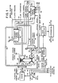
- Figure 1 is a block diagram of a continuously variable transmission and its relation to the hydraulic and electronic control systems;
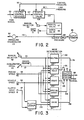
- Figure 2 is a partial block diagram depicting the relationship of the clutch control components as used in a previous design of the Applicants;
- Figure 3 is a block diagram of portions of the electronic control system of this invention, including a mode determination circuit;
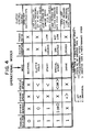
- Figure 4 is a chart useful in understanding the operating modes of the present invention;
- FIGURE 5 is a block diagram depicting major subsystems of the present invention; and
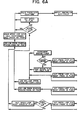
- FIGURES 6A and 6B together comprise is a flow chart useful in understanding the mode determination and control sequence of the present invention.
- FIGURE 1 shows the general power flow in an automotive layout from an
engine 20 over a shaft 21, flywheel-and-damper assembly 22 andtransmission input shaft 23 to driveprimary pulley 24 of a continuouslyvariable transmission 25. Input orprimary pulley 24 has afixed sheave 26 and amovable sheave 27, with a primarysheave servo chamber 28 positioned to admit and discharge fluid and thus adjust the position ofmovable sheave 27. Secondary oroutput pulley 30 has an axially fixedsheave 31 and an axiallymovable sheave 32, with a secondarysheave servo chamber 33 positioned to admit and discharge fluid to change the effective diameter ofpulley 30. Abelt 29 of metal or suitable elastomeric material intercouplespulleys secondary pulley 30 is supplied overshaft 39, in turn coupled to one side of clutch 34, the other side of which is coupled to a sleeve orquill shaft 35. Drive from this shaft is translated over a gear set (not shown) represented by dash-dot line 36 to a forward-reversegear selector assembly 37. Drive is passed from this selector assembly through agear reduction stage 38 to adifferential assembly 40, which passes output drive overshafts engine 20 toshafts clutch servo chamber 43. - Certain electrical signals are derived from the position of an
accelerator pedal 45, and passed over a plurality ofelectrical conductors electronic control system 50. The throttle signal online 46 is a function of the position ofpedal 45. The driver demand signal online 47 changes state as soon aspedal 45 is displaced from its at-rest position. The wide open throttle (WOT) signal online 48 changes state whenpedal 45 reaches the end of its travel.Electronic control system 50 operates jointly with ahydraulic control system 51 to regulate transmission operation and control engine operation. - A
manual selector lever 52 shown adjacenthydraulic control system 51 operates both to actuate certain components insystem 51 and to send a signal denoting the position oflever 52 overline 53 toelectronic control system 50. Preferably the signal online 53 is electronic but of course it can be mechanical or fluidic if desired. Another signal, indicating pressure in the clutch fluid line inhydraulic control system 51, is supplied overline 54 to theelectronic control system 50. A signal representing the temperature of the transmission or clutch fluid is passed fromhydraulic control system 51 overline 55 toelectronic control system 50. Other input signals to the electronic control system are provided overconductors conventional position sensor 60 is located adjacent engine output shaft 21, to provide on line 59 a signal which varies as the engine speed. Because of the solid coupling through the flywheel-and-damper assembly to inputpulley 24, the signal online 59 can also be considered to represent the transmission input speed. Anothersensor 61 is positionedadjacent shaft 39, to provide on line 57 a clutch input speed signal. Athird sensor 58 is positioned adjacentclutch output shaft 35, to provide online 56 an output speed signal, denoting the speed of thetransmission output shaft 39 when clutch 34 is engaged. This signal online 56 can function as a vehicle speed signal, as there is no slip in the driveline beyond the clutch. Of coursesensor 58 can be positioned anywhere betweensleeve shaft 35 anddrive shafts electronic control system 50 provides three output control signals inlines hydraulic control system 51. The signal on line 63 is a pump control signal to regulate the higher output pressure of a pump assembly within the hydraulic control system. The output signal online 64 is a ratio control signal, used to establish the desired ratio ofCVT 25. The third output signal, online 65, is used to regulate operation of clutch 34.Hydraulic control system 51 passes fluid throughconduit 66 to secondarysheave servo chamber 33, to hold the proper tension inbelt 29. The hydraulic control system provides the appropriate fluid flow throughline 67 to primarysheave servo chamber 28 to govern ratio changes, or maintain a steady ratio, ofCVT 25. In addition, a third fluid signal is provided throughconduit 68 to startingclutch servo chamber 43, to apply this clutch and complete the transfer of power through the drivetrain as described above, and to effect release of the clutch. - Before considering the details of the present invention, FIGURE 2 depicts a portion of the hydraulic control system set out in the last-referenced application. In particular the illustrated portion of the system depicts the regulation of the clutch apply pressure over
line 84 toclutch chamber 43 of the CVT. This pressure is regulated as a function of a pulse width modulated (pwm) signal online 65 to aclutch control solenoid 106, which in turn receives a control pressure fluid overline 95 and passes an output fluid signal overline 107 to aclutch control valve 108. Valve 108 also receives the control pressure inline 95, and fluid and line pressure over line 92. Valve 108 provides an output apply pressure inline 110 as a function of the pulse width modulated signal online 65. This pressure is then passed through a combination ofmanual valve 87 and aservo valve 88 to provide the clutch apply pressure.Valves manual selector 52 and a shift fork 111. Details ofvalves valves pressure transducer 113 is coupled over line 112 to the clutch apply line, and the transducer converts the pressure signal into an electrical signal for passage overline 54 to the associated electronic control system. The same numerals have been used in FIGURE 2 as in the last referenced application, so that the numerals in the present application above 120 indicate matter not referenced in the last-referenced application, or in FIGURE 1 of the present application. - In the present invention, a salient consideration in the inventive control system is that the clutch control system is only used when the clutch needs to be controlled. That is, when manual selector 52 (FIG. 1 and FIG. 3) is in the neutral position, or when it is in the drive position and the vehicle is moving down a freeway at a steady state speed, the clutch is not needed and clutch control system 121 (FIG. 3) is not employed. Particularly in accordance with the present invention, a
mode determination circuit 122 is provided to regulateclutch control system 121 to operate in one of a plurality of given modes, particularly including the start mode and the drive mode. The determination of the mode is a function of a plurality of input signals received as shown in the left portion of FIGURE 3. Withinmode determination circuit 122 are aneutral determination circuit 123, a clutchhold determination circuit 124, astart determination circuit 125, a specialstart determination circuit 126, and adrive determination circuit 127. These various specific mode determination circuits within theoverall determination circuit 122 receive a plurality of input signals as shown. These include a signal online 53 frommanual selector 52, indicating whether this selector is in neutral or not in neutral. The driver demand signal online 47 is provided whenever the accelerator pedal is depressed any amount from its at-rest position. The engine speed signal produced bysensor 60 and passed overline 59 is a function of the actual engine speed, and the vehiclespeed signal line 56 is likewise a function of the actual vehicle speed, or the speed of the clutch output shaft. Lastly the signal online 57 determined bysensor 61 adjacent toclutch input shaft 39 is the clutch input speed signal. The vehicle speed and clutch input speed signals are passed to a clutchlockup determination circuit 128, which, upon recognizing that the two signals are equal and therefore the clutch is locked up, provides an output signal online 130 to drivemode determination circuit 127 to indicate that the clutch is in fact not slipping. When the individual mode determination circuits 123-127 within theoverall determination circuit 122 receive a single signal (as in the neutral mode determination circuit 123) or the appropriate combination of signals (the other circuits 124-127), then the appropriate output signal is provided on one of the lines 131-135 toclutch control system 121 to determine the mode in which thesystem 121 operates to provide the pwm signal online 65. In understanding the mode determination, it will be helpful to consider the chart laid out in FIGURE 4 in conjunction with the diagramatic showing of FIGURE 3. - It will become apparent that the start and drive modes are significant because of their heavy use, but the other three modes, neutral, clutch hold and special start are refinements which add to the efficacy of the present invention. In particular the clutch hold
mode determination circuit 124 is advantageous in enhancing the operation of the system between the neutral and the start mode conditions. - Considering FIGURES 3 and 4 together, when the vehicle on which the control system of the invention is installed has its ignition turned on and the engine idling, with the manual selector in the neutral position, an "off" signal is passed over
line 53 to all of the individual mode determination circuits 123-127. So long as the vehicle remains in this condition, withmanual selector 52 in neutral, there is no closed loop control insystem 121, and the duty cycle of the pwm signal online 65 is 0%. in this condition the clutch control valve 108 (FIG. 2) is wide open, admiting the pressure from line 92 directly throughline 110 to themanual valve 87. - To enter the clutch hold mode,
manual selector 52 is moved from its neutral to the drive position, but the driver has not yet stepped on theaccelerator pedal 45. The engine speed must be less than a predetermined amount, such as 800 or 900 rpm, depending upon the particular engine and its idle speed. Likewise the vehicle speed must be less than a certain amount, such as 7 kilometers per hour, to be certain the vehicle is still at rest and is not already in motion at a significant speed. When this occursclutch hold circuit 124 provides an output signal online 132 toclutch control system 121, which in effect closes the control loop in which the clutch pressure serves as a reference. A reference of 40 psi was used in the preferred embodiment to initiate the start conditions in the clutch hold mode. This allows the clutch chamber to begin to be filled so that the clutch is ready to be taken up as soon as the driver steps into the accelerator, diminishing the lag time in the opera- ing sequence and thus enhancing the operation of the system. - To enter the start mode, the driver steps on the accelerator and changes the state of the driver demand signal on
line 47 from a 0 to a 1. The system also checks in startmode determination circuit 125, to be certain the vehicle speed online 56 indicates the vehicle is still at less than a predetermined speed. Because the vehicle was at rest, the transmission ratio is still in low and the clutch is not locked up. The output signal fromstart mode circuit 125 online 133 tellsclutch control system 121 to begin to pass torque through the clutch, and closes the control loop on an engine speed signal. This will be explained subsequently in conjunction with FIGURE 5. It is noted that the clutch is controlled in both the clutch hold and the start modes, but not in the neutral or the drive modes. - As the vehicle accelerates, the vehicle speed signal on
line 56 passed to clutchlockup determination circuit 128 gradually increases, until it matches the signal online 57, denoting the clutch input speed. This indicates the clutch is in fact locked up, and the clutch is no longer slipping. Drivemode determination circuit 127 also receives an engine speed signal overline 59, and when this signal becomes equal to, or greater than, a predetermined speed (depending upon the engine and the vehicle), then the output signal online 135 is passed to theclutch control system 121 to tell this system that the drive mode should be utilized in regulating the pwm signal online 65. - From the foregoing it is evident that the clutch hold, start and drive
mode determination circuit mode determination circuit 126 represents a refinement for special conditions, other than a normal start when the driver moves the manual selector into drive and steps into the accelerator. Thiscircuit 126 is helpful under circumstances such as when a vehicle is parked on a hill, and the brake released to allowthe vehicle to begin coasting down the hill. Under these conditions there is no driver demand signal online 47, and the vehicle speed is still less than some preset value. Likewise this mode is useful when the vehicle is at highway speeds, and the driver allows the vehicle to coast and then again steps into the accelerator. Under these conditions the special start circuit determines that there is a driver demand signal online 47, and the vehicle speed signal online 56 is at a level above some preset reference value. Thespecial start circuit 126 sends a signal overline 134 toclutch control system 121 to effectively provide closed loop control based on the actual clutch apply pressure, and to provide a pwm signal online 65 which varies, depending upon all the system variables. With this general perspective of themode determination circuit 122, which is very important to the operation of the present invention, details of the clutch control system and its operation will now be set out in connection with FIGURE 5. - FIGURE 5 depicts the general control arrangement for producing the pwm signal on
line 65 to control the duty cycle ofclutch control solenoid 106 and, ultimately, the clutch apply pressure inline 84. Themode determination circuit 122 described in connection with FIGURE 3 is a part of anoverall logic circuit 140 shown in FIGURE 5, which includes internal logic in addition to the mode determination circuitry. This logic arrangement will be described below in connection with FIGURES 6A and 6B. FIGURE 5 also includes other input signals described and shown in connection with FIGURE 1, namely, a throttle signal online 46; an engine speed signal on line 59 (shown in two places); a clutch input speed signal online 57; a clutch apply pressure feedback signal online 54; a clutch full pressure signal, a reference signal at a constant value applied overline 141 and the contacts ofswitch 142 toduty cycle generator 143; and a clutch take-up pressure signal applied overline 144 to asummation stage 145. The signal online 144 is also a reference level signal used in the clutch hold mode. Those skilled in the art will understand that the components depicted in FIGURE 5 are given to illustrate the control and information flow in the overall clutch strategy of the present invention, and do not necessarily indicate that a particular item is implemented in hardware if it is shown as a switch or a stage for producing a given result. - Considering the various operational modes already described in connection with FIGURE 4, the neutral mode can be virtually ignored for purposes of the system shown in FIGURE 5. In the neutral mode the clutch full pressume signal is passed over
line 141 toduty cycle generator 143, which outputs a 0% duty cycle signal online 65 toclutch control solenoid 106. In this system the O% duty cycle signal was utilized to provide a full line pressure fromvalve 108 intoline 110 to the manual valve. Thus the clutch is not actually controlling in the neutral mode, and only the reference signal fromline 141 in FIGURE 5 is utilized under these circumstances. - When the driver of the vehicle moves the manual selector into "drive", the
mode determination circuit 122 signals theclutch control system 121 to enter the clutch hold mode. In this mode the take-up pressure signal is applied overline 144 tosummation stage 145, and from this stage through anothersummation stage 146 to a pressureloop controller stage 147. In the clutch hold mode there is a feedback signal online 54 tosummation stage 146, and switch 142 is displaced from the illustrated position to engage the output side ofpressure loop controller 147. Accordingly the reference signal online 144 and the feedback signal online 54 cooperate to regulateduty cycle generator 143 to generate a specific pwm signal online 65, sufficient to apply a pressure in the clutch line to just take up the clutch without actually applying the clutch and passing torque through the driveline. In a conventional clutch arrangement this is analogous to filling the clutch before additional pressure is used to actually apply the clutch. Accordingly the clutch hold mode is a "get ready" type of state in which the system is ready to enter the actual start mode. The "get ready" command was, in effect, issued by the driver displacing the manual selector into the drive position. - When the driver steps on the accelerator to provide a driver demand signal on
line 47, and the vehicle speed is still below a very low level as indicated by the signal online 56, the startmode determination circuit 125 provides an output signal online 133 to put theclutch control system 121 in the start mode. In this mode the clutch apply pressure signal is fed back overline 54 tosummation stage 146 in FIG. 5, so that the pressure loop remains in operation, withswitch 142 displaced so that the signal fromcontroller 147 is fed toduty cycle generator 143. In addition, the major loop utilized with the engine speed signal online 59 is also closed in the (norma1) start mode. That is, the engine speed signal online 59 is applied to asummation stage 148, and from the output of this stage to aspeed loop controller 150.Controller 150 thus receives the speed loop error signal fromstage 148, and provides as its output signal one of the input signals, specifically the speed loop pressure error signal, to one input of anothersummation stage 151. The output ofstage 151 is passed through alimit stage 152, which insures that the clutch control pressure cannot drop below the take-up pressure. Fromlimit stage 152 the signal is passed through the contacts of aswitch 153, which remains open in the clutch hold mode but is closed in the start mode. This signal is then applied as one input tosummation stage 145, to complete the engine speed control loop for the start mode. - In addition to the use of the closed loop engine speed arrangement in the start mode,
feedforward circuit 154 is also employed, to compensate for the steady state engine torque which results as the driver steps into the accelerator. - In more detail, as
throttle signal 46 is applied to the input side offeedforward circuit 154, it also applied to the input of startmode schedule circuit 155. Thiscircuit 155 represents a memory arrangement in which different values of engine speed are stored as a function of throttle setting in degrees, or in the angular position of the accelerator with respect to a reference position. The degrees of throttle setting can also be measured as a function of the actual carburetor opening, or any other suitable reference arrangement for translating the throttle signal provided by the driver into an engine speed set point signal online 156. This signal representing the engine speed set point is then applied both to one input ofsummation stage 148 and, overline 157, to one input of anengine map circuit 158. This map is another storage arrangement for providing a steady state engine torque signal onoutput conductor 160 of the engine map circuit, as a function of the throttle signal input and the engine speed set point input. Those skilled in the art will understand this is another storage circuit in which the torque signal is derived from two inputs, the engine speed in rpm which is the set point signal online 157, and a throttle setting in degrees provided overline 146. This "map"appears as a series of throttle setting curves on a plane where the engine speed can be the abcissa or ordinate, and the engine torque (orthe output signal on line 160) is represented as the other reference scale. This nominal or steady state torque signal provided online 160 is then applied as one input to amultiplier circuit 161, which receives its other input signal overline 162 from aratio calculator circuit 163. Inturn calculator circuit 163 receives an engine speed signal overline 59 and a clutch input speed signal overline 57. The engine speed is the same as the input speed to the pulley system, and the clutch input speed signal is the same as the output speed from the pulley system. Accordinglyratio calculator 163 is effective to produce on line 162 a signal denoting the ratio of the CVT pulley system, and this signal when multiplied instage 161 is passed as a nominal clutch torque signal overline 164 to stage 165. The constant stored instage 165 for the particular system of the vehicle translates the nominal clutch torque signal into a nominal clutch pressure signal online 166, which is applied as one input tosummation stage 151.Feedforward circuit 154 remains in theclutch control system 121 throughout operation in the start mode. Thus in the start mode the minor loop of clutch pressure is active, the major loop including engine speed is active, and thefeedforward circuit 154 is also employed. - As the vehicle accelerates up to cruising speed, the input and output sides of the clutch reach an equal speed when the clutch is no longer slipping, and the clutch lock-up
circuit 128 signals this to the drivemode determination circuit 127. Inaddition circuit 127 also receives the engine speed signal overline 59, and when the drive mode should be entered, provides the appropriate output signal online 135 toclutch control system 121. In the drive mode the feedback clutch apply pressure signal online 54 is not used, and the clutch pressure is left equal to the line pressure. This is done by providing a 0% duty cycle signal overline 141 to theduty cycle generator 143, and the other components shown in FIGURE 5 are not used when controlling in the drive mode. - FIGURES 6A and 6B show various portions of the
logic circuit 140 of FIGURE 5, together with themode determination circuit 122 already described in general. As there shown when the system is initially energized the first operations occur in stage 170. Initially the status of the clutch is checked, and updates are performed on the clutch hold, special start and start mode flags. This output is to adecision box 171, which checks to see whether a minimum pressure is present in the clutch applied line. This minimum pressure is chosen to be about half that used in the clutch hold mode, when the clutch is just taken up but is short of being applied. Accordingly ifstage 171 determines that the clutch pressure is less than half of that "hold" pressure, then it recognizes that the system is in fact in the off position, and the off flag is set. This corresponds to the neutral position ofmanual selector 52. When the driver moves the selector from neutral to drive, the clutch apply line begins increasing in pressure, and eventually the output fromstage 171 will be a negative; this signal is sent todecision stage 172. In general the off flag will have been set from the conditions described previously, and thus the affirmative output fromstage 172 will be applied to stage 173 to perform the indicated actions. The "minimum pressure" approach used to determine the output ofdecision stage 171 is another way of determining whether the manual selector lever is in the neutral or the drive position. - The next decision stage is
stage 174, to determine whether the engage flag is set. Thisstage 174 is betweenstages - It has been explained that the clutch hold mode uses the closed loop of clutch pressure, and provides sufficient pressure in the clutch apply line to bring the clutch into position for engagement, but just short of clutch application. The purpose and function of the engage portion of the flow chart in FIGURE 6 is to provide a preset time interval, represented by an engage timer, to be certain that adequate fluid has entered the clutch chamber and the pressure has risen sufficiently, so that real time control can be commenced. Thus before the clutch hold mode is actually entered, the engage flag is set and the initializing of the pressure loop occurs as shown by the stages and boxes to the left of
stage 174. The legend "IC" means initial condition, and the numeral after IC indicates whether it is the first, second, third and so forth of the initial conditions. Thus after the engage timer times out, the engage flag is reset and the system is ready to enter the clutch hold mode, using the minimum line pressure as described above in connection with the signal applied over line 144 (FIG. 5) to summation stage . 145 in the clutch hold mode of operation. It is apparent that after the preset time provided by the engage interval, the system is ready to enter the clutch hold mode and operate in real time control of the CVT clutch. - When the clutch hold mode is entered as represented by
decision stage 175 in FIGURE 6A, then the appropriate pressure in the range of 40-45 psi is utilized in the clutch apply line to take up the slack of the clutch and the system is ready to enter the start mode. When this occurs the output ofstage 177 is affirmative, and the system controls as shown generally to the left ofstage 177, with the closing of the engine speed loop as already explained. To the right ofstage 177,stage 178 also determines whether the lockup flag is set, as occurs when clutch lockup stage 128 (FIG. 3) indicates there is no longer any slipping between the clutch components. Thus when there is no longer any slipping, the system automatically goes to the drive control mode, and the clutch control system shown and explained in connection with FIGURE 5 is essentially bypassed. The full line pressure is then supplied directly (through the manual and servo valves) toline 84 and to the clutch chamber, and the only control of the system is through the line pressure, which is a separate portion of the overall CVT system and not a part of the unobviousclutch control system 121 disclosed and claimed herein. That is, the clutch is no longer controlled through the system shown in FIGURE 5 when the system is in the drive mode.
Claims (14)
Applications Claiming Priority (2)
| Application Number | Priority Date | Filing Date | Title |
|---|---|---|---|
| US722578 | 1985-04-12 | ||
| US06/722,578 US4648496A (en) | 1985-04-12 | 1985-04-12 | Clutch control system for a continuously variable transmission |
Publications (2)
| Publication Number | Publication Date |
|---|---|
| EP0198694A1 EP0198694A1 (en) | 1986-10-22 |
| EP0198694B1 true EP0198694B1 (en) | 1989-03-08 |
Family
ID=24902443
Family Applications (1)
| Application Number | Title | Priority Date | Filing Date |
|---|---|---|---|
| EP86302726A Expired EP0198694B1 (en) | 1985-04-12 | 1986-04-11 | Clutch control system for a continuously variable transmission |
Country Status (7)
| Country | Link |
|---|---|
| US (1) | US4648496A (en) |
| EP (1) | EP0198694B1 (en) |
| JP (1) | JPH0811509B2 (en) |
| KR (1) | KR860008050A (en) |
| AU (1) | AU5574986A (en) |
| CA (1) | CA1252022A (en) |
| DE (1) | DE3662247D1 (en) |
Families Citing this family (49)
| Publication number | Priority date | Publication date | Assignee | Title |
|---|---|---|---|---|
| JPH0749824B2 (en) * | 1986-03-06 | 1995-05-31 | 本田技研工業株式会社 | Shift control method for continuously variable transmission for vehicle |
| US4982822A (en) * | 1986-12-01 | 1991-01-08 | Borg-Warner Corporation | Control system for controlling the line pressure in a continuously variable transmission |
| US4757886A (en) * | 1987-01-20 | 1988-07-19 | Ford Motor Company | Transmission clutch closed loop slip controller and method |
| US5206805A (en) * | 1987-03-13 | 1993-04-27 | Borg-Warner Automotive, Inc. | Continuously variable transmission clutch control system including special start mode operation |
| US5115395A (en) * | 1987-03-13 | 1992-05-19 | Borg-Warner Automotive, Inc. | Pulse width modulation technique |
| EP0281947B1 (en) * | 1987-03-13 | 1993-07-28 | Borg-Warner Automotive, Inc. | Temperature compensation technique for a continuously variable transmission control system |
| US4793454A (en) * | 1987-03-13 | 1988-12-27 | Borg-Warner Automotive, Inc. | Continuously variable transmission clutch control system |
| EP0283787B1 (en) * | 1987-03-13 | 1992-04-22 | Borg-Warner Automotive, Inc. | Special start technique for continuously variable transmission clutch control |
| US4984161A (en) * | 1987-03-24 | 1991-01-08 | Honda Giken Kogyo Kabushiki Kaisha | Method for controlling automatic transmissions |
| EP0288161B1 (en) * | 1987-03-24 | 1993-02-03 | Honda Giken Kogyo Kabushiki Kaisha | Method of controlling an automatic transmission |
| EP0308509B1 (en) * | 1987-03-25 | 1993-09-15 | Kabushiki Kaisha Komatsu Seisakusho | Hydraulic clutch pressure control apparatus |
| JP2631371B2 (en) * | 1987-08-10 | 1997-07-16 | スズキ株式会社 | Clutch control method for continuously variable transmission |
| DE3870552D1 (en) * | 1987-09-04 | 1992-06-04 | Honda Motor Co Ltd | DRIVETRAIN OF A CYCLING VEHICLE AND CONTROL METHOD FOR THIS. |
| CA1305674C (en) * | 1987-09-21 | 1992-07-28 | Kazuya Maki | Method of controlling clutch operation for vehicle and method of determining clutch engagement completion |
| US4875561A (en) * | 1987-10-09 | 1989-10-24 | Borg-Warner Automotive, Inc. | Dual clutch application area and control |
| JPH0721315B2 (en) * | 1987-10-13 | 1995-03-08 | 本田技研工業株式会社 | Clutch control method for continuously variable transmission for vehicle |
| JPH07117159B2 (en) * | 1987-11-05 | 1995-12-18 | 本田技研工業株式会社 | Shift control method for continuously variable transmission for vehicle |
| US4986396A (en) * | 1988-01-29 | 1991-01-22 | Fuji Jukogyo Kabushiki Kaisha | Control system for a clutch of a motor vehicle |
| JP2847779B2 (en) * | 1989-07-24 | 1999-01-20 | 日産自動車株式会社 | Continuously variable transmission |
| JP2847781B2 (en) * | 1989-07-28 | 1999-01-20 | 日産自動車株式会社 | Transmission control device |
| US5007512A (en) * | 1989-08-31 | 1991-04-16 | Borg-Warner Automotive, Inc. | Technique for clutch control in continuously variable transmission systems |
| US5285389A (en) * | 1989-09-15 | 1994-02-08 | Borg-Warner Automotive Inc. | Dual microprocessor architecture for control of a continuously variable transmission |
| US5062049A (en) * | 1989-09-15 | 1991-10-29 | Borg-Warner Automotive, Inc. | Control method and apparatus for continuously variable transmissions |
| JP2844363B2 (en) * | 1989-09-30 | 1999-01-06 | スズキ株式会社 | Continuous variable transmission control method |
| JP2660755B2 (en) * | 1989-09-30 | 1997-10-08 | スズキ株式会社 | Hydraulic clutch control method for continuously variable transmission |
| JP2706154B2 (en) * | 1989-10-05 | 1998-01-28 | スズキ株式会社 | Control device for automatic starting clutch |
| US5062050A (en) * | 1989-10-17 | 1991-10-29 | Borg-Warner Automotive, Inc. | Continuously variable transmission line pressure control |
| US5010989A (en) * | 1989-10-17 | 1991-04-30 | Borg-Warner Automotive, Inc. | Clutch control for high-response continuously variable transmission |
| DE3935438A1 (en) * | 1989-10-25 | 1991-05-02 | Fichtel & Sachs Ag | Vehicular friction clutch actuator dependent on speed difference - includes controller for linear redn. of desired value of difference between engine and prim. gear speeds |
| US5031481A (en) * | 1989-12-08 | 1991-07-16 | Borg-Warner Automotive, Inc. | Electro-hydraulic control system for a dual-pass continuously variable transmission |
| JP2994003B2 (en) * | 1990-06-15 | 1999-12-27 | マツダ株式会社 | Hydraulic control device for hydraulically operated transmission |
| DE4134268C2 (en) * | 1990-10-29 | 2001-05-17 | Volkswagen Ag | Drive arrangement for a motor vehicle |
| DE4100372A1 (en) * | 1991-01-09 | 1992-07-16 | Fichtel & Sachs Ag | ARRANGEMENT FOR CONTROLLING THE SLIP OF AN AUTOMATED FRICTION CLUTCH |
| DE4120602C2 (en) * | 1991-06-21 | 1995-02-02 | Porsche Ag | Method for the automatic control of a speed-changing starting device of a motor vehicle |
| US5168778A (en) * | 1991-08-29 | 1992-12-08 | Borg-Warner Automotive, Inc. | CVT downshift control strategy to minimize slip at the drive pulley |
| DE4332666B4 (en) * | 1992-10-07 | 2004-03-18 | Volkswagen Ag | Drive arrangement for a motor vehicle |
| US5314385A (en) * | 1992-11-13 | 1994-05-24 | Borg-Warner Automotive, Inc. | System for cooling a starting clutch of a continuously variable transmission |
| GB9310540D0 (en) * | 1993-05-21 | 1993-07-07 | Automotive Products Plc | A clutch control system |
| DE19833699A1 (en) * | 1998-07-27 | 2000-02-03 | Zahnradfabrik Friedrichshafen | Method for setting a ratio of a continuously variable automatic transmission with a variator |
| JP3745189B2 (en) * | 1999-07-21 | 2006-02-15 | 本田技研工業株式会社 | Control device for starting clutch in idle operation stop vehicle |
| JP3572393B2 (en) * | 1999-09-30 | 2004-09-29 | 日産自動車株式会社 | Slip prevention device for toroidal type continuously variable transmission |
| JP3991528B2 (en) * | 1999-10-12 | 2007-10-17 | 日本精工株式会社 | Starting clutch control device for continuously variable transmission |
| DE19952351A1 (en) * | 1999-10-30 | 2001-05-23 | Zahnradfabrik Friedrichshafen | Method and device for controlling and regulating a clutch in a continuously variable automatic transmission for a motor vehicle |
| GB2468909B (en) * | 2009-03-27 | 2012-06-20 | Dyson Technology Ltd | Clutch assembly |
| DE102016206591A1 (en) * | 2016-04-19 | 2017-10-19 | Robert Bosch Gmbh | Method and device for controlling an internal combustion engine |
| JP7410913B2 (en) * | 2021-09-30 | 2024-01-10 | 本田技研工業株式会社 | vehicle |
| CN114046318B (en) * | 2021-11-25 | 2024-05-17 | 潍柴动力股份有限公司 | Clutch control method, device and equipment based on cylinder pressure |
| CN114857183B (en) * | 2022-05-20 | 2024-05-17 | 潍柴动力股份有限公司 | Pneumatic clutch control method and device |
| CN116255406B (en) * | 2023-03-09 | 2025-11-21 | 上海汽车变速器有限公司 | Correction method, device, equipment and storage medium for clutch half-combining point |
Family Cites Families (20)
| Publication number | Priority date | Publication date | Assignee | Title |
|---|---|---|---|---|
| US3115049A (en) * | 1961-12-15 | 1963-12-24 | Ford Motor Co | Transmission control system |
| NL165821C (en) * | 1976-02-09 | 1981-05-15 | Doornes Transmissie Bv | INFLATABLE VARIABLE TRANSMISSION. |
| JPS52127559A (en) * | 1976-04-19 | 1977-10-26 | Nissan Motor Co Ltd | Electronic parallel shaft automatic transmission gear box |
| DE2700788C3 (en) * | 1977-01-11 | 1984-01-19 | Robert Bosch Gmbh, 7000 Stuttgart | Device for adjusting the shift jerk in motor vehicles |
| JPS5433430A (en) * | 1977-08-17 | 1979-03-12 | Mitsubishi Electric Corp | Clutch control apparatus for car |
| DE2946497A1 (en) * | 1979-11-17 | 1981-06-11 | Volkswagenwerk Ag, 3180 Wolfsburg | DEVICE FOR AUTOMATIC CLUTCH ACTUATION |
| US4515041A (en) * | 1980-05-21 | 1985-05-07 | Aisin Seiki Kabushiki Kaisha | Control system and method for a power delivery system having a continuously variable ratio transmission |
| JPS5715024A (en) * | 1980-06-26 | 1982-01-26 | Mitsubishi Electric Corp | Electromagnetic clutch controller for vehicle |
| JPS5790450A (en) * | 1980-11-27 | 1982-06-05 | Nippon Denso Co Ltd | Automatic change gear control apparatus for vehicle |
| GB2096253B (en) * | 1981-04-08 | 1985-04-03 | Automotive Prod Co Ltd | Controlling vehicle clutch during gear ratio changes |
| US4458318A (en) * | 1981-04-24 | 1984-07-03 | Borg-Warner Corporation | Control arrangement for a variable pulley transmission |
| US4522086A (en) * | 1981-04-24 | 1985-06-11 | Borg-Warner Corporation | Control system for continuously variable transmission |
| JPS5899546A (en) * | 1981-12-04 | 1983-06-13 | Fuji Heavy Ind Ltd | Electromagnetic clutch control device in infinitely variable gear of automobile |
| US4514811A (en) * | 1982-06-28 | 1985-04-30 | Ford Motor Company | Forward drive release system for automatic transmission |
| DE3370679D1 (en) * | 1982-09-22 | 1987-05-07 | Borg Warner | Hydraulic control system for continuously variable transmission |
| US4520912A (en) * | 1982-10-18 | 1985-06-04 | Borg-Warner Corporation | Hydraulically actuated starting clutch assembly |
| JPS5975841A (en) * | 1982-10-22 | 1984-04-28 | Nissan Motor Co Ltd | Control device for pneumatic type automatic clutch |
| JPS59213527A (en) * | 1983-05-20 | 1984-12-03 | Nissan Motor Co Ltd | Controller of automatic clutch |
| JPS6012343A (en) * | 1983-06-30 | 1985-01-22 | Isuzu Motors Ltd | Control unit of automatic clutch |
| DE3334717C2 (en) * | 1983-09-26 | 1994-09-15 | Wabco Vermoegensverwaltung | Device for the automatic or partially automatic control of an engine and a clutch of a motor vehicle |
-
1985
- 1985-04-12 US US06/722,578 patent/US4648496A/en not_active Expired - Lifetime
-
1986
- 1986-04-04 CA CA000505841A patent/CA1252022A/en not_active Expired
- 1986-04-08 AU AU55749/86A patent/AU5574986A/en not_active Abandoned
- 1986-04-11 DE DE8686302726T patent/DE3662247D1/en not_active Expired
- 1986-04-11 EP EP86302726A patent/EP0198694B1/en not_active Expired
- 1986-04-12 JP JP8484986A patent/JPH0811509B2/en not_active Expired - Fee Related
- 1986-04-12 KR KR1019860002793A patent/KR860008050A/en not_active Ceased
Also Published As
| Publication number | Publication date |
|---|---|
| JPH0811509B2 (en) | 1996-02-07 |
| KR860008050A (en) | 1986-11-12 |
| DE3662247D1 (en) | 1989-04-13 |
| US4648496A (en) | 1987-03-10 |
| AU5574986A (en) | 1986-10-16 |
| CA1252022A (en) | 1989-04-04 |
| EP0198694A1 (en) | 1986-10-22 |
| JPS61238528A (en) | 1986-10-23 |
Similar Documents
| Publication | Publication Date | Title |
|---|---|---|
| US4648496A (en) | Clutch control system for a continuously variable transmission | |
| KR100339113B1 (en) | How to control output torque of automatic gearbox | |
| US4462277A (en) | Hydraulic regulator for a V-belt type continuously variable transmission for vehicles | |
| US4470117A (en) | Control system for a continuously variable transmission for vehicles | |
| EP0104033B1 (en) | Hydraulic control system for continuously variable transmission | |
| EP0061735A2 (en) | Apparatus for controlling continuously variable V-belt transmission | |
| US5435795A (en) | Vehicle drivetrain control including CVT | |
| US4350058A (en) | Transmission control system for multi-ratio gear arrangement | |
| GB2239911A (en) | Control system for continuously variable transmission substitutes an ABS desired ratio for the normal desired ratio during antilock operation | |
| KR100512223B1 (en) | Belt-Type Continuously Variable transmission | |
| EP0231059A1 (en) | Control system for a continuously variable transmission | |
| GB2076084A (en) | Torque ratio control device for a v-belt type continuously variable transmission for vehicles | |
| EP0309967B1 (en) | Control systems for power trains provided in vehicles | |
| JPH0428567B2 (en) | ||
| US5009127A (en) | Transmission ratio control system for a continuously variable transmission | |
| JPH0564258B2 (en) | ||
| US4611285A (en) | Method of controlling automatic transmission shift pressure | |
| US5020392A (en) | Transmission ratio control system for a continuously variable transmission | |
| US4712453A (en) | Hydraulic control system for continuously variable transmission | |
| US5700224A (en) | CVT control system for vehicle drivetrain | |
| EP0207227A1 (en) | Control system for an infinitely variable transmission | |
| US4850935A (en) | Transmission ratio control system for a continuously variable transmission | |
| US4923433A (en) | Transmission ratio control system for a continuously variable transmission | |
| GB2321938A (en) | Ratio control system of a continuously-variable transmission | |
| US7510501B2 (en) | Hydraulic control system of belt-type continuously variable transmission for vehicle |
Legal Events
| Date | Code | Title | Description |
|---|---|---|---|
| PUAI | Public reference made under article 153(3) epc to a published international application that has entered the european phase |
Free format text: ORIGINAL CODE: 0009012 |
|
| AK | Designated contracting states |
Kind code of ref document: A1 Designated state(s): DE FR GB IT NL |
|
| 17P | Request for examination filed |
Effective date: 19861209 |
|
| 17Q | First examination report despatched |
Effective date: 19871211 |
|
| GRAA | (expected) grant |
Free format text: ORIGINAL CODE: 0009210 |
|
| AK | Designated contracting states |
Kind code of ref document: B1 Designated state(s): DE FR GB IT NL |
|
| PG25 | Lapsed in a contracting state [announced via postgrant information from national office to epo] |
Ref country code: NL Effective date: 19890308 |
|
| ITF | It: translation for a ep patent filed | ||
| REF | Corresponds to: |
Ref document number: 3662247 Country of ref document: DE Date of ref document: 19890413 |
|
| PGFP | Annual fee paid to national office [announced via postgrant information from national office to epo] |
Ref country code: NL Payment date: 19890430 Year of fee payment: 4 |
|
| ET | Fr: translation filed | ||
| NLV1 | Nl: lapsed or annulled due to failure to fulfill the requirements of art. 29p and 29m of the patents act | ||
| PLBE | No opposition filed within time limit |
Free format text: ORIGINAL CODE: 0009261 |
|
| STAA | Information on the status of an ep patent application or granted ep patent |
Free format text: STATUS: NO OPPOSITION FILED WITHIN TIME LIMIT |
|
| 26N | No opposition filed | ||
| PG25 | Lapsed in a contracting state [announced via postgrant information from national office to epo] |
Ref country code: GB Effective date: 19900411 |
|
| GBPC | Gb: european patent ceased through non-payment of renewal fee | ||
| ITTA | It: last paid annual fee | ||
| PGFP | Annual fee paid to national office [announced via postgrant information from national office to epo] |
Ref country code: FR Payment date: 20030403 Year of fee payment: 18 |
|
| PGFP | Annual fee paid to national office [announced via postgrant information from national office to epo] |
Ref country code: DE Payment date: 20030430 Year of fee payment: 18 |
|
| PG25 | Lapsed in a contracting state [announced via postgrant information from national office to epo] |
Ref country code: DE Free format text: LAPSE BECAUSE OF NON-PAYMENT OF DUE FEES Effective date: 20041103 |
|
| PG25 | Lapsed in a contracting state [announced via postgrant information from national office to epo] |
Ref country code: FR Free format text: LAPSE BECAUSE OF NON-PAYMENT OF DUE FEES Effective date: 20041231 |
|
| REG | Reference to a national code |
Ref country code: FR Ref legal event code: ST |
|
| PG25 | Lapsed in a contracting state [announced via postgrant information from national office to epo] |
Ref country code: IT Free format text: LAPSE BECAUSE OF NON-PAYMENT OF DUE FEES;WARNING: LAPSES OF ITALIAN PATENTS WITH EFFECTIVE DATE BEFORE 2007 MAY HAVE OCCURRED AT ANY TIME BEFORE 2007. THE CORRECT EFFECTIVE DATE MAY BE DIFFERENT FROM THE ONE RECORDED. Effective date: 20050411 |