EP0198580A2 - Grounding connector - Google Patents
Grounding connector Download PDFInfo
- Publication number
- EP0198580A2 EP0198580A2 EP86301316A EP86301316A EP0198580A2 EP 0198580 A2 EP0198580 A2 EP 0198580A2 EP 86301316 A EP86301316 A EP 86301316A EP 86301316 A EP86301316 A EP 86301316A EP 0198580 A2 EP0198580 A2 EP 0198580A2
- Authority
- EP
- European Patent Office
- Prior art keywords
- connector
- cable
- housing
- panel
- conductive
- Prior art date
- Legal status (The legal status is an assumption and is not a legal conclusion. Google has not performed a legal analysis and makes no representation as to the accuracy of the status listed.)
- Withdrawn
Links
Images

Classifications
-
- H—ELECTRICITY
- H01—ELECTRIC ELEMENTS
- H01R—ELECTRICALLY-CONDUCTIVE CONNECTIONS; STRUCTURAL ASSOCIATIONS OF A PLURALITY OF MUTUALLY-INSULATED ELECTRICAL CONNECTING ELEMENTS; COUPLING DEVICES; CURRENT COLLECTORS
- H01R9/00—Structural associations of a plurality of mutually-insulated electrical connecting elements, e.g. terminal strips or terminal blocks; Terminals or binding posts mounted upon a base or in a case; Bases therefor
- H01R9/03—Connectors arranged to contact a plurality of the conductors of a multiconductor cable, e.g. tapping connections
- H01R9/05—Connectors arranged to contact a plurality of the conductors of a multiconductor cable, e.g. tapping connections for coaxial cables
- H01R9/0512—Connections to an additional grounding conductor
-
- H—ELECTRICITY
- H01—ELECTRIC ELEMENTS
- H01R—ELECTRICALLY-CONDUCTIVE CONNECTIONS; STRUCTURAL ASSOCIATIONS OF A PLURALITY OF MUTUALLY-INSULATED ELECTRICAL CONNECTING ELEMENTS; COUPLING DEVICES; CURRENT COLLECTORS
- H01R4/00—Electrically-conductive connections between two or more conductive members in direct contact, i.e. touching one another; Means for effecting or maintaining such contact; Electrically-conductive connections having two or more spaced connecting locations for conductors and using contact members penetrating insulation
- H01R4/58—Electrically-conductive connections between two or more conductive members in direct contact, i.e. touching one another; Means for effecting or maintaining such contact; Electrically-conductive connections having two or more spaced connecting locations for conductors and using contact members penetrating insulation characterised by the form or material of the contacting members
- H01R4/66—Connections with the terrestrial mass, e.g. earth plate, earth pin
Definitions
- This invention relates generally to electrical connections in electronic equipment and, more particularly, to connectors for the grounding of shielded cables coupled to such equipment.
- a shielded cable can be grounded for the purpose of reducing or eliminating electromagnetic and radio frequency interference (EMI/RFI) in the equipment to which it is coupled.
- EMI/RFI electromagnetic and radio frequency interference
- US-A-4 416 501 discloses the use of a U-shaped clamp and a ferrule for grounding the conductive shield of a cable to a shroud for a wiring block.
- the use of inner and outer flanged tubes to ground the outer conductor of a coaxial cable is also disclosed in US-A-3 142 721. In both instances, skill, dexterity and time are required to insert the tubular elements properly in a stripped end of a cable and the parts must then be crimped or clamped in place.
- a general object of the invention is to provide an improved form of grounding connection.
- a grounding connector comprises a conductive shield of a cable in a stripped length of said cable and a dielectric housing for encasing said stripped length, wherein said housing is provided with a slot for mounting the connector on an edge of a conductive panel and said element has an integral arm projecting therefrom and through said housing for making yielding contact with the edge of the conductive panel.
- a shielded cable is provided with a preassembled grounding connector.
- the cable has a layer of insulation over a conductive shield.
- a conductive element in contact with the shield.
- the element has integral arms projecting through a dielectric housing which encases the stripped length and the housing has opposed slots adapting it to fit in a notch in a conductive panel with the arms in electrical contact with the panel.
- a cable 10 passes through a connector 12 which includes a dielectric housing 14 and a conductive element 16 forming a grounding contact.
- the housing 14 takes the form of a bushing with a U-shaped channel 18 extending along both sides and around its bottom. Along its sides, housing 14 has slots 20, 22 opening into channel 18.
- connector 12 is mounted in a notch 24 on a conductive panel 26, one or more edges of the panel fit closely in and extend through slots 20, 22 into channel 18.
- panel 26 is cast from aluminum and is a part of the chassis in a computer.
- Cable 10 has a plurality of insulated conductors 28 covered, in turn, by an aluminized layer 30 of a polymeric film, a flexible conductive shield 32 and an outer layer 34 of insulation.
- the inner conductors 28 may be either stranded or single wires and shield 32 is usually a braided screen.
- Connector 12 can also be used on other shielded cables, e.g. coaxial cables.
- cable 10 is prepared by stripping outer insulation 34 from an intermediate length to expose shield 32. Then, contact 16 is attached to the exposed shield, as by soldering. At one end, contact 16 has angularly disposed, projecting lips 36 which conform generally to the outline of shield 32. At its other end, contact 16 has opposed, lateral extensions or arms 38. There is an angularly disposed, flat tab 39 at the end of each arm 38. Following attachment of the contact 16, cable 10 is placed in a fixture, arms 38 are bent upwardly and housing 12 is moulded thereon from a suitable thermoplastic, e.g. polyvinyl chloride.
- a suitable thermoplastic e.g. polyvinyl chloride.
- connector 12 slides into place in a notch 24 in the upper edge of panel 26 is shown in Figures 1, 3 and 4. Tightness of the fit in slots 20, 22 provides strain relief for cable 10.
- the contact 16 is stamped and formed from spring metal stock, e.g. beryllium copper or phosphor bronze. During fabrication of the connector, arms 38 are bent inwardly but the spacing of tabs 39 is greater than the width of notches 24 in panel 26, as shown in Figure 3. Thus, as the connector is mounted in a notch, tabs 39 make a wiping contact, and are biased into engagement with the edge of the panel to provide a reliable, low impedance connection to ground, thereby yielding an EMI/RFI shield for components in a computer or other electronic equipment to which cable 10 is coupled.
Abstract
Description
- This invention relates generally to electrical connections in electronic equipment and, more particularly, to connectors for the grounding of shielded cables coupled to such equipment.
- It is, of course, known that a shielded cable can be grounded for the purpose of reducing or eliminating electromagnetic and radio frequency interference (EMI/RFI) in the equipment to which it is coupled. For example, US-A-4 416 501 discloses the use of a U-shaped clamp and a ferrule for grounding the conductive shield of a cable to a shroud for a wiring block. The use of inner and outer flanged tubes to ground the outer conductor of a coaxial cable is also disclosed in US-A-3 142 721. In both instances, skill, dexterity and time are required to insert the tubular elements properly in a stripped end of a cable and the parts must then be crimped or clamped in place. A general object of the invention is to provide an improved form of grounding connection.
- In accordance with the present invention, a grounding connector comprises a conductive shield of a cable in a stripped length of said cable and a dielectric housing for encasing said stripped length, wherein said housing is provided with a slot for mounting the connector on an edge of a conductive panel and said element has an integral arm projecting therefrom and through said housing for making yielding contact with the edge of the conductive panel.
- In a preferred construction a shielded cable is provided with a preassembled grounding connector. The cable has a layer of insulation over a conductive shield. In a stripped length of the cable, there is a conductive element in contact with the shield. The element has integral arms projecting through a dielectric housing which encases the stripped length and the housing has opposed slots adapting it to fit in a notch in a conductive panel with the arms in electrical contact with the panel.
- The invention may be understood more readily and various other features of the invention may become apparent from consideration of the following description.
- In the accompanying drawings:
- Figure 1 is a perspective view of a grounding connector constructed in accordance with the present invention;
- Figure 2 is a perspective view of the cable and contact shown in Figure 1;
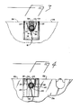
- Figure 3 is a transverse cross section taken on line 3-3 in Figure 1; and
- Figure 4 is a sectional end view of the connector shown in Figures 1 and 3.
- As shown in Figure 1, a
cable 10 passes through aconnector 12 which includes adielectric housing 14 and aconductive element 16 forming a grounding contact. Thehousing 14 takes the form of a bushing with a U-shapedchannel 18 extending along both sides and around its bottom. Along its sides,housing 14 hasslots channel 18. Whenconnector 12 is mounted in anotch 24 on aconductive panel 26, one or more edges of the panel fit closely in and extend throughslots channel 18. Typically,panel 26 is cast from aluminum and is a part of the chassis in a computer. -
Cable 10 has a plurality ofinsulated conductors 28 covered, in turn, by analuminized layer 30 of a polymeric film, a flexibleconductive shield 32 and anouter layer 34 of insulation. Theinner conductors 28 may be either stranded or single wires andshield 32 is usually a braided screen.Connector 12 can also be used on other shielded cables, e.g. coaxial cables. - Referring now to Figure 2,
cable 10 is prepared by strippingouter insulation 34 from an intermediate length to exposeshield 32. Then,contact 16 is attached to the exposed shield, as by soldering. At one end,contact 16 has angularly disposed, projectinglips 36 which conform generally to the outline ofshield 32. At its other end,contact 16 has opposed, lateral extensions orarms 38. There is an angularly disposed,flat tab 39 at the end of eacharm 38. Following attachment of thecontact 16,cable 10 is placed in a fixture,arms 38 are bent upwardly andhousing 12 is moulded thereon from a suitable thermoplastic, e.g. polyvinyl chloride. - The manner in which
connector 12 slides into place in anotch 24 in the upper edge ofpanel 26 is shown in Figures 1, 3 and 4. Tightness of the fit inslots cable 10. Thecontact 16 is stamped and formed from spring metal stock, e.g. beryllium copper or phosphor bronze. During fabrication of the connector,arms 38 are bent inwardly but the spacing oftabs 39 is greater than the width ofnotches 24 inpanel 26, as shown in Figure 3. Thus, as the connector is mounted in a notch,tabs 39 make a wiping contact, and are biased into engagement with the edge of the panel to provide a reliable, low impedance connection to ground, thereby yielding an EMI/RFI shield for components in a computer or other electronic equipment to whichcable 10 is coupled. - Another advantage of the connector disclosed herein is that the same sized
housing 14, i.e. one mould can be used for several sizes of cables and contacts. Instead of the soldered attachment ofcontact 16 to shield 32, a crimped barrel could be provided. These and other advantages and variations will occur to those skilled in the art without departing from the present invention which, accordingly, is intended to be limited only by the scope of the appended claims.
Claims (8)
Applications Claiming Priority (2)
| Application Number | Priority Date | Filing Date | Title |
|---|---|---|---|
| US06/723,525 US4613191A (en) | 1985-04-15 | 1985-04-15 | Grounding connector |
| US723525 | 1985-04-15 |
Publications (2)
| Publication Number | Publication Date |
|---|---|
| EP0198580A2 true EP0198580A2 (en) | 1986-10-22 |
| EP0198580A3 EP0198580A3 (en) | 1989-05-10 |
Family
ID=24906635
Family Applications (1)
| Application Number | Title | Priority Date | Filing Date |
|---|---|---|---|
| EP86301316A Withdrawn EP0198580A3 (en) | 1985-04-15 | 1986-02-24 | Grounding connector |
Country Status (7)
| Country | Link |
|---|---|
| US (1) | US4613191A (en) |
| EP (1) | EP0198580A3 (en) |
| JP (1) | JPS61240584A (en) |
| KR (1) | KR860008628A (en) |
| AU (1) | AU584037B2 (en) |
| BR (1) | BR8601633A (en) |
| CA (1) | CA1260096A (en) |
Cited By (2)
| Publication number | Priority date | Publication date | Assignee | Title |
|---|---|---|---|---|
| FR2652207A1 (en) * | 1989-09-21 | 1991-03-22 | Framatome Sa | Device for earthing electrical cables |
| DE102017109561A1 (en) * | 2017-05-04 | 2018-11-08 | Sennheiser Electronic Gmbh & Co. Kg | Audio unit and method for making an audio unit |
Families Citing this family (9)
| Publication number | Priority date | Publication date | Assignee | Title |
|---|---|---|---|---|
| DE4038690A1 (en) * | 1990-12-05 | 1992-06-11 | Standard Elektrik Lorenz Ag | Communications appts. housing with HF-tight cable input - clamps cable between clamp plate and carrier plate with complementary V=shaped formations |
| DK0858690T3 (en) * | 1995-10-30 | 2002-05-06 | Nkt Cables Gmbh | Device for connecting the electrically conductive sheath to a wire with an earth conductor |
| FR2759815B1 (en) * | 1997-02-20 | 1999-04-02 | Gec Alsthom Transport Sa | DEVICE AND METHOD FOR EARTHING SHIELDED BRAIDS OF ARMORED CABLES |
| DE20101067U1 (en) * | 2001-01-19 | 2001-05-10 | Daume Karin Maschinenteile | Device for electrically contacting a stripped outer conductor of a coaxial cable |
| US6548762B2 (en) * | 2001-02-21 | 2003-04-15 | Andrew Corporation | Transmission line grounding lug |
| US6544072B2 (en) | 2001-06-12 | 2003-04-08 | Berg Technologies | Electrical connector with metallized polymeric housing |
| DE20113219U1 (en) * | 2001-08-16 | 2003-01-02 | Daume Karin | Device for electrically conductive contacting of a stripped outer conductor of a coaxial cable |
| US7780461B1 (en) | 2009-03-03 | 2010-08-24 | Mike Vernica | Midpoint cable electrical ground clamp |
| CN112310670B (en) * | 2020-10-23 | 2022-03-11 | 广东电网有限责任公司 | Grounding device |
Citations (3)
| Publication number | Priority date | Publication date | Assignee | Title |
|---|---|---|---|---|
| US3142721A (en) * | 1960-12-19 | 1964-07-28 | Burndy Corp | Connector for joining the outer conductor of a coaxial cable to a wall |
| DE2348882A1 (en) * | 1973-09-28 | 1975-04-17 | Siemens Ag | Coaxial cable connector with tension relief clamp - has flexible angled plates pressed by collar down on and against cable |
| EP0080365A1 (en) * | 1981-11-23 | 1983-06-01 | E.I. Du Pont De Nemours And Company | Termination of shielded cable |
Family Cites Families (3)
| Publication number | Priority date | Publication date | Assignee | Title |
|---|---|---|---|---|
| US1310054A (en) * | 1919-07-15 | Protectivei device for electrical apparatus | ||
| US3568128A (en) * | 1968-12-09 | 1971-03-02 | George W Taylor | Ground clamp |
| DE3311651A1 (en) * | 1983-03-30 | 1984-10-04 | Siemens AG, 1000 Berlin und 8000 München | Device for making electrical contact with a cable screen |
-
1985
- 1985-04-15 US US06/723,525 patent/US4613191A/en not_active Expired - Fee Related
-
1986
- 1986-02-24 EP EP86301316A patent/EP0198580A3/en not_active Withdrawn
- 1986-04-10 BR BR8601633A patent/BR8601633A/en unknown
- 1986-04-11 AU AU56021/86A patent/AU584037B2/en not_active Ceased
- 1986-04-14 KR KR1019860002831A patent/KR860008628A/en not_active Application Discontinuation
- 1986-04-14 JP JP61085821A patent/JPS61240584A/en active Pending
- 1986-04-15 CA CA000506732A patent/CA1260096A/en not_active Expired
Patent Citations (3)
| Publication number | Priority date | Publication date | Assignee | Title |
|---|---|---|---|---|
| US3142721A (en) * | 1960-12-19 | 1964-07-28 | Burndy Corp | Connector for joining the outer conductor of a coaxial cable to a wall |
| DE2348882A1 (en) * | 1973-09-28 | 1975-04-17 | Siemens Ag | Coaxial cable connector with tension relief clamp - has flexible angled plates pressed by collar down on and against cable |
| EP0080365A1 (en) * | 1981-11-23 | 1983-06-01 | E.I. Du Pont De Nemours And Company | Termination of shielded cable |
Cited By (2)
| Publication number | Priority date | Publication date | Assignee | Title |
|---|---|---|---|---|
| FR2652207A1 (en) * | 1989-09-21 | 1991-03-22 | Framatome Sa | Device for earthing electrical cables |
| DE102017109561A1 (en) * | 2017-05-04 | 2018-11-08 | Sennheiser Electronic Gmbh & Co. Kg | Audio unit and method for making an audio unit |
Also Published As
| Publication number | Publication date |
|---|---|
| CA1260096A (en) | 1989-09-26 |
| AU5602186A (en) | 1986-10-23 |
| EP0198580A3 (en) | 1989-05-10 |
| US4613191A (en) | 1986-09-23 |
| AU584037B2 (en) | 1989-05-11 |
| JPS61240584A (en) | 1986-10-25 |
| BR8601633A (en) | 1986-12-16 |
| KR860008628A (en) | 1986-11-17 |
Similar Documents
| Publication | Publication Date | Title |
|---|---|---|
| US6722898B2 (en) | Connector with improved grounding means | |
| US10777936B2 (en) | Electrical device having a ground termination component with strain relief | |
| EP0118168B1 (en) | Electrical plug connector and receptacle therefor | |
| KR100390311B1 (en) | Shielded-cable connector improved in transmission characteristics | |
| US4619487A (en) | Flat cable connector with grounding clip | |
| US5823825A (en) | System for terminating the shield of a high speed cable | |
| EP1187268B1 (en) | Coaxial connector module and method of fabricating same | |
| US5711686A (en) | System for terminating the shield of a high speed cable | |
| US5725387A (en) | System for terminating the shield of a high speed cable | |
| EP0793297A2 (en) | System for terminating the shield of a high speed cable | |
| US5447441A (en) | Connector box for shielded cables | |
| US4613191A (en) | Grounding connector | |
| US5768771A (en) | System for terminating the shield of a high speed cable | |
| EP0542075B1 (en) | Method of terminating miniature coaxial electrical connector and resulting terminated connector | |
| US5415568A (en) | Electrical contact and electrical connector using such contact | |
| US6364701B1 (en) | System for terminating the shield of a high speed cable | |
| US4500157A (en) | Mounting and grounding clamp for shielded cable | |
| JP3398890B2 (en) | Electrical connector with coaxial cable termination | |
| US5637016A (en) | HF plug connection system | |
| EP0473049B1 (en) | A conductive shell for clamping onto a shielded electrical connector | |
| JP3016041B2 (en) | Connection device for shielded twisted cable | |
| US6106334A (en) | Shielded cable connector | |
| US20040097111A1 (en) | Cable end connector assembly and method of assembling the assembly | |
| JPH04298099A (en) | Housing for electronic device | |
| EP0135122A2 (en) | Cable connector and method of coupling flat multi-wire cable |
Legal Events
| Date | Code | Title | Description |
|---|---|---|---|
| PUAI | Public reference made under article 153(3) epc to a published international application that has entered the european phase |
Free format text: ORIGINAL CODE: 0009012 |
|
| AK | Designated contracting states |
Kind code of ref document: A2 Designated state(s): AT BE CH DE FR GB IT LI LU NL SE |
|
| PUAL | Search report despatched |
Free format text: ORIGINAL CODE: 0009013 |
|
| AK | Designated contracting states |
Kind code of ref document: A3 Designated state(s): AT BE CH DE FR GB IT LI LU NL SE |
|
| 17P | Request for examination filed |
Effective date: 19890615 |
|
| STAA | Information on the status of an ep patent application or granted ep patent |
Free format text: STATUS: THE APPLICATION HAS BEEN WITHDRAWN |
|
| 18W | Application withdrawn |
Withdrawal date: 19900925 |
|
| R18W | Application withdrawn (corrected) |
Effective date: 19900925 |
|
| RIN1 | Information on inventor provided before grant (corrected) |
Inventor name: PAPA, RALPH ANTHONY |