EP0198147A1 - Aktenschrank - Google Patents
Aktenschrank Download PDFInfo
- Publication number
- EP0198147A1 EP0198147A1 EP85870168A EP85870168A EP0198147A1 EP 0198147 A1 EP0198147 A1 EP 0198147A1 EP 85870168 A EP85870168 A EP 85870168A EP 85870168 A EP85870168 A EP 85870168A EP 0198147 A1 EP0198147 A1 EP 0198147A1
- Authority
- EP
- European Patent Office
- Prior art keywords
- drawer
- documents
- slat
- filing cabinet
- cabinet
- Prior art date
- Legal status (The legal status is an assumption and is not a legal conclusion. Google has not performed a legal analysis and makes no representation as to the accuracy of the status listed.)
- Withdrawn
Links
Images

Classifications
-
- A—HUMAN NECESSITIES
- A47—FURNITURE; DOMESTIC ARTICLES OR APPLIANCES; COFFEE MILLS; SPICE MILLS; SUCTION CLEANERS IN GENERAL
- A47B—TABLES; DESKS; OFFICE FURNITURE; CABINETS; DRAWERS; GENERAL DETAILS OF FURNITURE
- A47B51/00—Cabinets with means for moving compartments up and down
-
- A—HUMAN NECESSITIES
- A47—FURNITURE; DOMESTIC ARTICLES OR APPLIANCES; COFFEE MILLS; SPICE MILLS; SUCTION CLEANERS IN GENERAL
- A47B—TABLES; DESKS; OFFICE FURNITURE; CABINETS; DRAWERS; GENERAL DETAILS OF FURNITURE
- A47B63/00—Cabinets, racks or shelf units, specially adapted for storing books, documents, forms, or the like
- A47B63/06—Cabinets, racks or shelf units, specially adapted for storing books, documents, forms, or the like with parts, e.g. trays, card containers, movable on pivots or on chains or belts
Definitions
- the present invention relates to a filing cabinet for documents, and in particular to a device by means of which it is possible to store documents, files or the like and remove them by means of a calling device simple and efficient.
- a device of this kind can be of special use for collecting different documents, which are stored there in different places to constitute a file; for the search and / or storage of documents or files in order to be able to remove them and consult them later as simply as possible; etc.
- the filing cabinet according to the invention consists for this purpose essentially in the combination of a cabinet with vertical drawers, which are preferably divided into compartments, a lifting mechanism capable of lifting and lowering said drawers and means capable successively establish a connection and interrupt it between the lifting mechanism and a drawer.
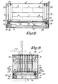
- the filing cabinet represented by the figures of the appended drawings mainly consists of a cabinet 1, capable of being placed in any location, for example near a desk, and provided with a plurality of vertical drawers 2, which can be partially or entirely extracted from the cabinet 1 by means of an appropriate mechanism for removing from a locker a raised drawer, either a bundle or all the documents therein or placing new documents therein, or even for remove one or more documents from a locker to form a bundle in combination with other documents from the same locker or lockers from other drawers.
- Each drawer 2 according to this embodiment has a certain number of compartments, which, in the embodiment according to FIG. 1, are indicated by reference numbers ranging from 3 to 8, while each drawer 2 can be opened , in other words can be slid upwards, by means of a lifting mechanism which can be controlled dice by a keyboard.
- This lifting mechanism consists, according to this embodiment, essentially of a certain number of connecting members arranged horizontally and vertically, capable of being controlled by a reversible motor 9, constituted by slats or toothed belts 10 to 17, and by a slat 18 fixed thereto, so that the latter can be placed horizontally under the desired drawer 2 and then moves upwards to push the relevant drawer 2 out of this cabinet 1 to a well-determined position.
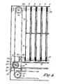
- the toothed belts 10-17 are endless toothed belts, passing over a number of toothed wheels 19, each belt 10-17 being kept under tension by two of these toothed wheels 19.
- the notched vertical belts 10-13 are coupled to the motor 9 directly by the motor shaft 20, and by the required connections, constituted by transmissions, via the notched belts 14 and 15 and the tree 21.
- the horizontal notched belts 16 and 17, on which the slat 18 is fixed, are carried at their ends by two toothed wheels 19, which are fixed by means of two interrupted shafts 22 on a frame 23, capable of moving by movement vertical alternative. All this frame 23 and the members which are integral therewith are fixed on the belts 10 to 13 arranged vertically, by means of free-wheel couplings 24 provided at the ends of the shafts 22.
- These free-wheel couplings 24 each consist of '' a toothed wheel 25, tightly pushed against the notched side of one of the strands of one of the vertical toothed belts by means of two rollers 26, which force the belt toothed to move in an arc on the toothed wheel 25.
- the toothed wheels 25 are, by means of the shafts 22, positively coupled to the toothed wheels 19, which support the toothed belts 16 and 17 and are capable of driving them .
- the cabinet 1 is provided with the indides thinkable to keep drawers 2 on track.
- these guides arranged on either side of the drawers 2 consist of small discs 28 also spaced from one another, extending partially between the drawers 2 and wedged on shafts fixed on the upper side of the cabinet 1.
- Between the longitudinal slats 30 of the frame 23 are provided similar guides in the form of small discs 31 fixed on a shaft 32. As this latter guide device performs an alternating vertical movement with the frame 23, the drawers 2 move easily in the same way.
- the drawers 2 are supported in their rest position by stops or other similar devices. In the embodiment according to FIG. 1, the drawers 2 rest in their lower position with appendages 33 on the shafts 29.
- the filing cabinet according to the invention is, at an easily accessible location, provided with a control panel not shown, which is connected to a control unit, so that the motor 9, generally arranged at the bottom of cabinet 1, is appropriately controlled to slide the desired drawer up.
- the motor 9 stops when the slat 18 is under the desired drawer 2. Then, the direction of rotation of the motor 9 is automatically reversed, so that the direction of movement of the vertical toothed belts 10 to 13 is also reversed. As the frame 23 does not encounter great resistance in this direction, the freewheel coupling 24 is driven with these toothed belts without the toothed wheel being rotated. It follows that the slat 18 moves upwards and pushes up the drawer 2 which is located above it. As soon as this drawer 2 is lifted sufficiently from the cabinet 1, an interrupt contact again stops the motor. Thanks to the guides 28 and 31, the drawer 2 remains constantly in its vertical plane.
- This command results in the motor 9 resuming rotation in the aforementioned first direction, so that the frame 23 and therefore also the slat 18 move downward. But as soon as the frame 23 reaches its stop 27, this vertical movement is, thanks to the freewheel coupling, transformed into a horizontal movement of the slat 18, so that it first moves more towards the front and is then brought back along the lower side of the assembly formed by the toothed belts 16 and 17. The batten 13 automatically stops again under the last, the assembly thus having returned to its initial state.
- connection between the slat 18 and the drawers 2 is preferably carried out, not necessarily, by simple contact, for example by letting the drawers 2 rest in their open position simply on the slat 18, as shown in the figures . Indeed, it is thus obtained that in the event of a possible blockage of a drawer 2, during the closing, the slat 18 and the toothed belts can move further without risk of rupture for the belts. In addition, if a hand is accidentally taken by a drawer 2 which closes, it is not pulled further down. Finally, such a loose connection makes it possible at all times to extract the drawers 2 from the filing cabinet by simple manual intervention.
- control unit concerned can be produced by an appropriate electrical connection by means of control and detection elements known per se.
- control and detection elements known per se.
- the control unit consists of a reduced number of elements and can therefore be very simple. .
- control units are suitable for equipping the filing cabinet without departing from the scope of the invention.
- the simplest form is the use of limit switches. If a slow-running motor is used, the limit switches may even be removed.
- the filing cabinet according to the invention has two motor devices, each provided with at least one electric motor, a relatively weak motor ensuring the horizontal movement of the slat. 13 and a more powerful engine providing its drive verti- cal.
- the freewheel coupling is eliminated in this case.
- a filing cabinet according to the invention can also be used for other purposes than the classification of documents, namely, for example, for the classification of materials arranged in different compartments of drawers 2.
Landscapes
- Drawers Of Furniture (AREA)
- Graft Or Block Polymers (AREA)
- Vehicle Step Arrangements And Article Storage (AREA)
- Power-Operated Mechanisms For Wings (AREA)
Applications Claiming Priority (2)
| Application Number | Priority Date | Filing Date | Title |
|---|---|---|---|
| BE2/60555A BE901190A (nl) | 1984-12-04 | 1984-12-04 | Klasseermeubel voor dokumenten. |
| BE2060555 | 1984-12-04 |
Publications (1)
| Publication Number | Publication Date |
|---|---|
| EP0198147A1 true EP0198147A1 (de) | 1986-10-22 |
Family
ID=95858461
Family Applications (1)
| Application Number | Title | Priority Date | Filing Date |
|---|---|---|---|
| EP85870168A Withdrawn EP0198147A1 (de) | 1984-12-04 | 1985-12-04 | Aktenschrank |
Country Status (9)
| Country | Link |
|---|---|
| EP (1) | EP0198147A1 (de) |
| JP (1) | JPS61502803A (de) |
| AU (1) | AU5230186A (de) |
| BE (1) | BE901190A (de) |
| BR (1) | BR8507088A (de) |
| FI (1) | FI863126L (de) |
| NO (1) | NO863096L (de) |
| OA (1) | OA08375A (de) |
| WO (1) | WO1986003387A1 (de) |
Families Citing this family (4)
| Publication number | Priority date | Publication date | Assignee | Title |
|---|---|---|---|---|
| WO2005115764A2 (en) | 2004-05-21 | 2005-12-08 | Esselte | Punching and binding system and elements thereof |
| CN105167422A (zh) * | 2015-09-01 | 2015-12-23 | 上海大学 | 一种循环旋转升降书架 |
| CN107822336A (zh) * | 2017-11-17 | 2018-03-23 | 王鹏 | 一种升降书架 |
| CN111728378A (zh) * | 2020-06-24 | 2020-10-02 | 武汉花都科技集团有限公司 | 区域可调装配式文件柜 |
Citations (2)
| Publication number | Priority date | Publication date | Assignee | Title |
|---|---|---|---|---|
| GB438926A (en) * | 1934-02-20 | 1935-11-26 | Remington Rand Inc | Improvements relating to filing cabinets |
| FR885390A (fr) * | 1941-08-22 | 1943-09-13 | Dispositif pour placer et extraire des fiches reposant dans des réceptacles placés verticalement |
-
1984
- 1984-12-04 BE BE2/60555A patent/BE901190A/nl not_active IP Right Cessation
-
1985
- 1985-12-04 JP JP61500195A patent/JPS61502803A/ja active Pending
- 1985-12-04 WO PCT/BE1985/000021 patent/WO1986003387A1/fr not_active Ceased
- 1985-12-04 FI FI863126A patent/FI863126L/fi not_active IP Right Cessation
- 1985-12-04 BR BR8507088A patent/BR8507088A/pt unknown
- 1985-12-04 EP EP85870168A patent/EP0198147A1/de not_active Withdrawn
- 1985-12-04 AU AU52301/86A patent/AU5230186A/en not_active Abandoned
-
1986
- 1986-07-31 NO NO863096A patent/NO863096L/no unknown
- 1986-08-04 OA OA58916A patent/OA08375A/xx unknown
Patent Citations (2)
| Publication number | Priority date | Publication date | Assignee | Title |
|---|---|---|---|---|
| GB438926A (en) * | 1934-02-20 | 1935-11-26 | Remington Rand Inc | Improvements relating to filing cabinets |
| FR885390A (fr) * | 1941-08-22 | 1943-09-13 | Dispositif pour placer et extraire des fiches reposant dans des réceptacles placés verticalement |
Also Published As
| Publication number | Publication date |
|---|---|
| FI863126A7 (fi) | 1986-07-31 |
| FI863126A0 (fi) | 1986-07-31 |
| JPS61502803A (ja) | 1986-12-04 |
| NO863096D0 (no) | 1986-07-31 |
| BR8507088A (pt) | 1987-03-31 |
| NO863096L (no) | 1986-07-31 |
| WO1986003387A1 (fr) | 1986-06-19 |
| AU5230186A (en) | 1986-07-01 |
| OA08375A (en) | 1988-02-29 |
| FI863126L (fi) | 1986-07-31 |
| BE901190A (nl) | 1985-03-29 |
Similar Documents
| Publication | Publication Date | Title |
|---|---|---|
| CH652992A5 (fr) | Trieuse de feuilles de papier, notamment des photocopies. | |
| EP1369213B1 (de) | Vorrichtung zur Trennung Befestigungspunkte, die gestapelte Kartonbogen verbinden | |
| BE897245A (fr) | Dispositif destine a elargir et a ralentir un courant de bouteilles ou d'autres objets du meme centre poses droits | |
| FR2690909A1 (fr) | Support de pile auxiliaire pour un dispositif de levage d'une pile de feuilles. | |
| EP0326463B1 (de) | Förderer zum Fortbewegen in horizontaler Längsrichtung von auf Rollenlaufwerken liegenden Einzellasten | |
| FR2759068A1 (fr) | Dispositif d'alimentation en articles de courrier | |
| EP2439155B1 (de) | Transportplatte und Anlage zur Erstellung von Lebensmitteln mit solchen Transportplatten | |
| EP0198147A1 (de) | Aktenschrank | |
| FR2614013A1 (fr) | Dispositif pour le transport de pots de filature comportant un organe de transport circulant | |
| CH689976A5 (fr) | Dispositif de commande de la prise d'un élément en plaque par des pinces au sein d'une machine de traitement de tels éléments. | |
| EP3176356B1 (de) | Schliessvorrichtung | |
| EP2109575B1 (de) | Vorrichtung zur lagerung von objekten auf einer mobilen palette | |
| FR2948648A1 (fr) | Appareil d'extraction et de chargement de bacs dans un magasin de stockage | |
| FR2979939A3 (fr) | Contrevent pliant | |
| FR2638145A1 (fr) | Appareil de distribution automatique de documents | |
| EP0013531B1 (de) | Rollgang für die Handhabung von Waren | |
| EP1320463B1 (de) | Maschine zum kuvertieren einer menge von dokumenten | |
| FR2726506A1 (fr) | Trieuse a agrafage incorpore | |
| FR2482057A1 (fr) | Dispositif pour la prehension de bacs de rangement et pour leur entrainement horizontal le long d'une plate-forme de manutention | |
| FR2508879A1 (fr) | Dispositif pour l'ouverture symetrique de signatures composees de plusieurs feuilles et pour leur disposition sur une selle de transport | |
| FR2662677A1 (fr) | Dispositif pour transporter une charge, selon une allee de derivation, entre un convoyeur a rouleaux et un poste de prise de charge par un translateur. | |
| FR2829477A1 (fr) | Dispositif automatique de vidage en continu de caisses ou analogue | |
| EP1116842B1 (de) | Ausgleichsvorrichtung für eine Hubtür | |
| FR2830611A1 (fr) | Dispositif pour le deplacement d'une cible pour la pratique du tir | |
| FR2541192A1 (fr) | Classeur a anneaux |
Legal Events
| Date | Code | Title | Description |
|---|---|---|---|
| PUAI | Public reference made under article 153(3) epc to a published international application that has entered the european phase |
Free format text: ORIGINAL CODE: 0009012 |
|
| AK | Designated contracting states |
Kind code of ref document: A1 Designated state(s): AT CH DE FR GB IT LI LU NL SE |
|
| 17P | Request for examination filed |
Effective date: 19870417 |
|
| STAA | Information on the status of an ep patent application or granted ep patent |
Free format text: STATUS: THE APPLICATION HAS BEEN WITHDRAWN |
|
| 18W | Application withdrawn |
Withdrawal date: 19871126 |