EP0197783A2 - Ostomievorrichtung - Google Patents
Ostomievorrichtung Download PDFInfo
- Publication number
- EP0197783A2 EP0197783A2 EP86302531A EP86302531A EP0197783A2 EP 0197783 A2 EP0197783 A2 EP 0197783A2 EP 86302531 A EP86302531 A EP 86302531A EP 86302531 A EP86302531 A EP 86302531A EP 0197783 A2 EP0197783 A2 EP 0197783A2
- Authority
- EP
- European Patent Office
- Prior art keywords
- wall
- flange
- ostomy
- parts
- coupling
- Prior art date
- Legal status (The legal status is an assumption and is not a legal conclusion. Google has not performed a legal analysis and makes no representation as to the accuracy of the status listed.)
- Withdrawn
Links
Images
Classifications
-
- A—HUMAN NECESSITIES
- A61—MEDICAL OR VETERINARY SCIENCE; HYGIENE
- A61F—FILTERS IMPLANTABLE INTO BLOOD VESSELS; PROSTHESES; DEVICES PROVIDING PATENCY TO, OR PREVENTING COLLAPSING OF, TUBULAR STRUCTURES OF THE BODY, e.g. STENTS; ORTHOPAEDIC, NURSING OR CONTRACEPTIVE DEVICES; FOMENTATION; TREATMENT OR PROTECTION OF EYES OR EARS; BANDAGES, DRESSINGS OR ABSORBENT PADS; FIRST-AID KITS
- A61F5/00—Orthopaedic methods or devices for non-surgical treatment of bones or joints; Nursing devices ; Anti-rape devices
- A61F5/44—Devices worn by the patient for reception of urine, faeces, catamenial or other discharge; Colostomy devices
- A61F5/445—Colostomy, ileostomy or urethrostomy devices
- A61F5/448—Means for attaching bag to seal ring
Definitions
- This invention relates to an ostomy appliance and to a body side ostomy member for use in an ostomy appliance.
- ostomy appliances in which an ostomy bag is connected to a medical grade adhesive pad via a pair of interengageable .coupling elements, one element being on the pad and one on the bag are known.
- the pad is usually adhesively attached to the wearer and need not be disturbed for some days.
- One successful system is described in British Patent No. 1 571 657 entitled Coupling for Joining an Ostomy Bag to a Pad which issued to P.L. Steer, et al. Such an arrangement allows a bag to be removed and replaced without detaching the pad from the body of the wearer, thereby allowing the bag to be emptied or drained.
- a body side ostomy member which includes a medical grade adhesive pad having, or which can be provided with, a stomal aperture, and a coupling having one part captive to, but telescopically slidable to, another part to provide access for the fingers or thumb of a wearer beneath a lateral flange of the coupling when the parts are spaced from one another.
- a body side ostomy member for attachment to a pad of medical grade adhesive, the member including one part having a lateral flange and a coupling element, said one part have a lateral flange and a coupling element, said one part being slidable on, and relative to, another part, in a direction towards and away from the body of the wearer to provide a space between the specified parts to enable a thumb or fingers to be placed therebetween.
- a body side ostomy member for use in attaching an ostomy bag to a wearer, includes:.
- the stomal orifice will usually be substantially circular and the first and second walls may be substantially cylindrical, but walls of oval or polygonal or any other closed loop shape which defines a stomal aperture may be used.
- the interengaging coupling elements may be as disclosed and illustrated in British Patent No. 1 571 657 entitled Coupling for Joining an Ostomy Bag to a Pad which issued to P.L. Steer, et al. referred to above.
- Other known interengaging coupling elements e.g., those shown in British Patent Nos. 1 583 027 and 2 101 249 may also be used.
- the first and second walls are located within one another for telescopic sliding movement, and the movement is limited by a particularly convenient arrangement which also serves a sealing or anti-leakage function.
- the innermost wall is provided with an outwardly extending resilient flexible peripheral seal strip
- the outermost wall is provided at its other end with an inwardly extending resilient flexible peripheral seal strip.
- Each of these seal strips extends towards, and its distal portion engages, the confronting surface of the other wall.
- the walls are substantially coaxial cylinders sliding one within the other, and the inner wall is connected to (or integral with) the flange which is secured to the medical grade adhesive pad. In the telescopically extended condition of the two walls, the presence of the peripheral strips prevents the two walls, and hence the two parts of the body side member, from being separated, In other words, the walls are held captive to each other once assembled.
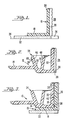
- FIGS. 1-4 for simplicity of illustration, only those portions of the device on one side of a central axis are shown, it being understood that in the preferred embodiment of the invention the device is symmetrical about an axial line constituting the center line of the stomal orifice.
- the body side member according to the invention is symmetrical about a central axis, but an oval or other shaped configuration rather than a circular configuration, may be equally well employed, and the scope of the invention includes oval and other non-circular configurations.
- the body side ostomy member illustrated in FIGS. 1-4 includes a first part 10 (shown in FIG. 1) which is made captive to another (second) part 12 (shown in FIG. 2). These two parts 10, 12 are telescopically slidable relative to one another to provide access for the fingers or thumb of a wearer beneath a lateral flange 14 on the second part 12, when the parts 10, 12 are in their telescopically extended condition, as shown in FIG. 4.
- the first part 10, as shown in FIG. 1, includes a laterally extending flange 18 and a substantially cylindrical wall 20.
- the flange 18 is, or can be, secured to a pad 22 of medical grade adhesive material, to thereby adhere the pad 22 to the skin 24 of the wearer of the ostomy appliance.
- the adhesive pad 22 has a central stomal aperture 26 therein with which the stomal aperture 28 defined by the cylindrical wall 20 is substantially aligned in use.
- the flange 18 and the wall 20 are made in one piece. Alternatively, they may be made separately and suitably assembled together, e.g., with adhesive.
- the upper end of the cylindrical wall 20, as shown in the drawing, which is the outer end when the ostomy appliance is being worn, has an outwardly radially extending resilient flexible peripheral seal strip 30 which extends completely around the wall 20 encircling the aperture 28.
- the second part 12 has a substantially cylindrical wall 32 encircling the stomal aperture 28.
- the wall 32 is integral with the flange coupling element 34.
- the wall 32 is also integral with a radially inwardly extending resilient flexible peripheral seal strip 36, which is dimensioned so that its rim 38, which is spaced from the wall 32 engages the external surface 40 of the wall 32.
- the effect of the seal strips 30, 36 is to make the first part 10 captive to the second part 12 once these parts 10, 12 have been assembled together. They also permit the second part 12 to slide telescopically relative to the wall 20 of the first part 10.
- an upper peripheral region of the wall 20 is recessed or rebated so as to allow the seal strip 30 to move inwardly. This is useful when the parts are being assembled as the second part 12 can then be placed over and pushed down on the cylindrical wall 20 of the first part 12. Once assembled, the seal strips 30 and 36 spring resiliently outwardly in the case of seal strip 30 and inwardly in the case of seal strip 36, so engaging the opposed surface and mutually guiding the parts 10 and 12 for limited telescopically sliding relationship.
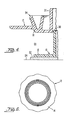
- the coupling element 34 preferred in the present invention is a coupling element substantially as disclosed and illustrated in U.K. Patent Application No. 84 21099 filed August 20, 1984.
- the second part 12 has a flange 14 with circular stomal orifice 28 therein.
- the flange 14 is made in one piece with a coupling element 34. This is formed by two diverging ribs 46 and 48.
- the ribs 46, 48 are joined adjacent to the flange 14 and diverge in a direction away from the plate. As shown in cross-section, the ribs 46, 48 define a V-formation which encircles the wall 32.
- the wall 32 serves as a chute 22 which conducts discharged waste directly into the interior of an ostomy bag 51 and prevents such waste from becoming lodged in recessed or crevices in the interengaged coupling elements.
- a body side coupling part 12 can be interengaged with a bag side coupling element 50 is illustrated.
- an internal rim 52 on the element 50 snaps over the rib 46 and is received in a recess defined by a stepped formation comprising L-shaped flat surfaces on the rib 46.
- This engagement maintains the coupling elements 12 and 50 securely connected together so that the bag 51 is securely connected to the two part body side member 10, 12. Due to the small radial overlap and the inherent flexibility of the plastic used, the coupling elements 34 and 50 may be manually separated easily, even by elderly or infirm persons.
- the bag side member 12 and the body side member 10 may be reconnected without discomfort, because the user can place his fingers or thumbs behind the flange 14 when the bag side member 12 is in its telescopically extended condition, and then press the two members together manually. In this process, no significant force is applied inwardly towards the abdomen so avoiding pain or discomfort.
- the angle between the surfaces 56 and 58 of the respective 46, 48 may be about 40°.
- the axial length of the surface 66 may be about 0.010 inch (0.25 mm) and the radial extent of the surface 68 may be about 0.0084 inch 10.203 to 0.213 mm) and preferably should not be less than 0.008 inch.
- the preferred plastics material for the parts 10 and 12 is low density polyethylene and this may have a Shore A hardness which is conventional in couplings of the kinds shown in British Patent No. 1 571 657.
- peripheral strips 30 and 36 there could be an O-ring or a pair of O-rings disposed between the outer surface of the wall 20 and the inner wall of the part 32.
- This O-ring could be adhesively attached to one or other part, or could be lodged in a peripheral channel in either of these parts.
- two 0-rings one could be lodged in a peripheral channel in each part..
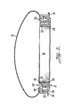
- FIG. 6 is a front view illustrating a scalloped edge on the flange 14.
- the thickness and shape of the flexible strips may be varied from that illustrated; also the inherent flexibility of the plastics material employed may be adjusted as appropriate by using conventional plasticizers.
Landscapes
- Health & Medical Sciences (AREA)
- Epidemiology (AREA)
- Nursing (AREA)
- Orthopedic Medicine & Surgery (AREA)
- Engineering & Computer Science (AREA)
- Biomedical Technology (AREA)
- Heart & Thoracic Surgery (AREA)
- Vascular Medicine (AREA)
- Life Sciences & Earth Sciences (AREA)
- Animal Behavior & Ethology (AREA)
- General Health & Medical Sciences (AREA)
- Public Health (AREA)
- Veterinary Medicine (AREA)
- Orthopedics, Nursing, And Contraception (AREA)
Applications Claiming Priority (2)
| Application Number | Priority Date | Filing Date | Title |
|---|---|---|---|
| GB8509168 | 1985-04-10 | ||
| GB08509168A GB2173403B (en) | 1985-04-10 | 1985-04-10 | Ostomy appliance |
Publications (2)
| Publication Number | Publication Date |
|---|---|
| EP0197783A2 true EP0197783A2 (de) | 1986-10-15 |
| EP0197783A3 EP0197783A3 (de) | 1988-06-08 |
Family
ID=10577390
Family Applications (1)
| Application Number | Title | Priority Date | Filing Date |
|---|---|---|---|
| EP86302531A Withdrawn EP0197783A3 (de) | 1985-04-10 | 1986-04-04 | Ostomievorrichtung |
Country Status (9)
| Country | Link |
|---|---|
| US (1) | US4781708A (de) |
| EP (1) | EP0197783A3 (de) |
| JP (1) | JPS61276555A (de) |
| AU (1) | AU595191B2 (de) |
| CA (1) | CA1278483C (de) |
| DK (1) | DK160186A (de) |
| GB (1) | GB2173403B (de) |
| NO (1) | NO165522C (de) |
| ZA (1) | ZA862586B (de) |
Cited By (4)
| Publication number | Priority date | Publication date | Assignee | Title |
|---|---|---|---|---|
| EP0334489A3 (de) * | 1988-03-23 | 1991-06-19 | E.R. Squibb & Sons, Inc. | Ostomiekupplung |
| EP0927549A1 (de) * | 1997-12-30 | 1999-07-07 | Eurotec Beheer B.V. | Zwischenstück mit beweglichem Flansch für den Gebrauch mit einem zweiteiligen Ostomiesystem |
| WO2002015827A1 (en) * | 2000-08-21 | 2002-02-28 | Svein Jacob Andersen | Arrangement at a stoma cuff |
| US7250040B2 (en) | 2001-01-10 | 2007-07-31 | Bristol-Myers Squibb Company | Arrangement at a stoma bag |
Families Citing this family (11)
| Publication number | Priority date | Publication date | Assignee | Title |
|---|---|---|---|---|
| EP0251502A1 (de) * | 1986-06-09 | 1988-01-07 | SMITH & NEPHEW UNITED, INC. | Ostomievorrichtung mit niederem Profil |
| GB8629424D0 (en) * | 1986-12-09 | 1987-01-21 | Craig Med Prod Ltd | Ostomy bag coupling |
| GB2205041A (en) * | 1987-05-22 | 1988-11-30 | Craig Med Prod Ltd | Ostomy coupling |
| GB2237993A (en) * | 1989-11-17 | 1991-05-22 | Squibb & Sons Inc | Ostomy coupling |
| CA2028618C (en) * | 1989-11-17 | 2001-12-11 | Peter Leslie Steer | Ostomy coupling |
| EP0461007B1 (de) * | 1990-06-08 | 1995-11-08 | B. Braun Biotrol | Stomavorrichtung |
| GB9020218D0 (en) * | 1990-09-15 | 1990-10-24 | Smiths Industries Plc | Medico-surgical collection bag assemblies |
| US5163930A (en) * | 1990-10-03 | 1992-11-17 | E.R. Squibb | Convex insert for ostomy device |
| JP2534783Y2 (ja) * | 1991-02-15 | 1997-05-07 | アルケア株式会社 | 外科用吻合装置 |
| DK75993D0 (da) * | 1993-06-25 | 1993-06-25 | Ole Jensen | A ostomy appliance comprising a flexible pouch and a faceplate, a flexible pouch of an ostomy appliance, and a faceplate of an ostomy appliance |
| US6673056B2 (en) | 2001-11-05 | 2004-01-06 | Hollister Incorporated | Snap-in insert for convex ostomy faceplate |
Family Cites Families (10)
| Publication number | Priority date | Publication date | Assignee | Title |
|---|---|---|---|---|
| DK116151B (da) * | 1967-03-10 | 1969-12-15 | Pharma Plast As | Colostomibandage. |
| GB1571657A (en) * | 1977-03-30 | 1980-07-16 | Kingsdown Medical Consultants | Ostomy bag |
| NZ186585A (en) * | 1977-03-30 | 1981-03-16 | Kingsdown Medical Consultants | Coupling for joining pad or dressing to an ostomy bag |
| GB1583027A (en) * | 1978-01-12 | 1981-01-21 | Kingdom Medical Consultants Lt | Coupling for joining an ostomy bag to a pad |
| GB2101249B (en) * | 1981-06-26 | 1985-01-03 | Kingsdown Medical Consultants | Coupling for an ostomy bag |
| US4464178A (en) * | 1981-11-25 | 1984-08-07 | Dalton Michael J | Method and apparatus for administration of fluids |
| BE892073A (fr) * | 1982-02-09 | 1982-05-27 | Staar Sa | Dispositif de maintien d'un verrou magnetique pour tourne disque |
| US4419100A (en) * | 1982-03-16 | 1983-12-06 | Hollister Incorporated | Ostomy appliance and faceplate attachment therefor |
| AU572784B2 (en) * | 1982-06-24 | 1988-05-19 | E.R. Squibb & Sons, Inc. | Ostomy bag connection |
| GB2163350B (en) * | 1984-08-20 | 1988-01-20 | Craig Med Prod Ltd | Ostomy appliance coupling elements |
-
1985
- 1985-04-10 GB GB08509168A patent/GB2173403B/en not_active Expired
-
1986
- 1986-04-04 EP EP86302531A patent/EP0197783A3/de not_active Withdrawn
- 1986-04-07 ZA ZA862586A patent/ZA862586B/xx unknown
- 1986-04-09 NO NO861385A patent/NO165522C/no unknown
- 1986-04-09 AU AU55778/86A patent/AU595191B2/en not_active Ceased
- 1986-04-09 DK DK160186A patent/DK160186A/da not_active IP Right Cessation
- 1986-04-10 JP JP61084033A patent/JPS61276555A/ja active Pending
- 1986-04-10 CA CA000506309A patent/CA1278483C/en not_active Expired - Lifetime
-
1987
- 1987-04-13 US US07/038,464 patent/US4781708A/en not_active Expired - Lifetime
Cited By (4)
| Publication number | Priority date | Publication date | Assignee | Title |
|---|---|---|---|---|
| EP0334489A3 (de) * | 1988-03-23 | 1991-06-19 | E.R. Squibb & Sons, Inc. | Ostomiekupplung |
| EP0927549A1 (de) * | 1997-12-30 | 1999-07-07 | Eurotec Beheer B.V. | Zwischenstück mit beweglichem Flansch für den Gebrauch mit einem zweiteiligen Ostomiesystem |
| WO2002015827A1 (en) * | 2000-08-21 | 2002-02-28 | Svein Jacob Andersen | Arrangement at a stoma cuff |
| US7250040B2 (en) | 2001-01-10 | 2007-07-31 | Bristol-Myers Squibb Company | Arrangement at a stoma bag |
Also Published As
| Publication number | Publication date |
|---|---|
| AU5577886A (en) | 1986-10-16 |
| AU595191B2 (en) | 1990-03-29 |
| DK160186A (da) | 1986-10-11 |
| GB2173403B (en) | 1988-10-05 |
| US4781708A (en) | 1988-11-01 |
| NO165522B (no) | 1990-11-19 |
| ZA862586B (en) | 1986-10-06 |
| NO861385L (no) | 1986-10-13 |
| GB8509168D0 (en) | 1985-05-15 |
| NO165522C (no) | 1991-02-27 |
| JPS61276555A (ja) | 1986-12-06 |
| GB2173403A (en) | 1986-10-15 |
| CA1278483C (en) | 1991-01-02 |
| EP0197783A3 (de) | 1988-06-08 |
| DK160186D0 (da) | 1986-04-09 |
Similar Documents
| Publication | Publication Date | Title |
|---|---|---|
| US4931045A (en) | Low profile ostomy bag coupling | |
| US4781708A (en) | Telescoping coupling for an ostomy appliance | |
| US5125917A (en) | Ostomy appliances | |
| US4642107A (en) | Adapter for use with two piece ostomy system | |
| US4387713A (en) | Disposable discharge collector for a drainable stoma pouch with wiper | |
| US5163930A (en) | Convex insert for ostomy device | |
| AU700851B2 (en) | Self-aligning ostomy device | |
| US4867749A (en) | Urostomy appliance | |
| CA1265014A (en) | Ostomy appliance | |
| EP0171255A2 (de) | Ostomievorrichtung | |
| US5098420A (en) | One-piece ileostomy or colostomy bag connector | |
| NZ238170A (en) | Ostomy device coupling ring structure | |
| EP0882437A2 (de) | Ostomievorrichtung mit einer konkaven/konvexen Front-Platte | |
| EP0334489B1 (de) | Ostomiekupplung | |
| US5195996A (en) | Ostomy device with improved coupling system | |
| JPS58209349A (ja) | ストマ看護装置 | |
| US4923452A (en) | Apparatus for tending a stoma | |
| JPS6214845Y2 (de) |
Legal Events
| Date | Code | Title | Description |
|---|---|---|---|
| PUAI | Public reference made under article 153(3) epc to a published international application that has entered the european phase |
Free format text: ORIGINAL CODE: 0009012 |
|
| AK | Designated contracting states |
Kind code of ref document: A2 Designated state(s): AT BE CH DE FR GB IT LI LU NL SE |
|
| PUAL | Search report despatched |
Free format text: ORIGINAL CODE: 0009013 |
|
| AK | Designated contracting states |
Kind code of ref document: A3 Designated state(s): AT BE CH DE FR GB IT LI LU NL SE |
|
| 17P | Request for examination filed |
Effective date: 19881201 |
|
| RAP1 | Party data changed (applicant data changed or rights of an application transferred) |
Owner name: E.R. SQUIBB & SONS, INC. |
|
| 17Q | First examination report despatched |
Effective date: 19900529 |
|
| STAA | Information on the status of an ep patent application or granted ep patent |
Free format text: STATUS: THE APPLICATION HAS BEEN WITHDRAWN |
|
| 18W | Application withdrawn |
Withdrawal date: 19901105 |
|
| R18W | Application withdrawn (corrected) |
Effective date: 19901105 |
|
| RIN1 | Information on inventor provided before grant (corrected) |
Inventor name: STEER, PETER LESLIE |