EP0197722A2 - Vorrichtung zum Glätten von Blättern - Google Patents
Vorrichtung zum Glätten von Blättern Download PDFInfo
- Publication number
- EP0197722A2 EP0197722A2 EP86302316A EP86302316A EP0197722A2 EP 0197722 A2 EP0197722 A2 EP 0197722A2 EP 86302316 A EP86302316 A EP 86302316A EP 86302316 A EP86302316 A EP 86302316A EP 0197722 A2 EP0197722 A2 EP 0197722A2
- Authority
- EP
- European Patent Office
- Prior art keywords
- sheets
- sheet
- decurling
- curl
- baffles
- Prior art date
- Legal status (The legal status is an assumption and is not a legal conclusion. Google has not performed a legal analysis and makes no representation as to the accuracy of the status listed.)
- Granted
Links
- 239000000463 material Substances 0.000 claims abstract description 31
- 238000005192 partition Methods 0.000 claims description 22
- 238000005452 bending Methods 0.000 claims description 20
- 238000012545 processing Methods 0.000 claims description 6
- 230000009977 dual effect Effects 0.000 claims 1
- 239000000843 powder Substances 0.000 description 12
- 239000002245 particle Substances 0.000 description 6
- 238000012546 transfer Methods 0.000 description 6
- 230000032258 transport Effects 0.000 description 6
- 230000008901 benefit Effects 0.000 description 3
- 238000004140 cleaning Methods 0.000 description 3
- 238000011161 development Methods 0.000 description 3
- 238000000034 method Methods 0.000 description 3
- 239000008187 granular material Substances 0.000 description 2
- 230000007246 mechanism Effects 0.000 description 2
- 238000012986 modification Methods 0.000 description 2
- 230000004048 modification Effects 0.000 description 2
- 230000008569 process Effects 0.000 description 2
- 239000000758 substrate Substances 0.000 description 2
- 238000006424 Flood reaction Methods 0.000 description 1
- 229920000134 Metallised film Polymers 0.000 description 1
- BUGBHKTXTAQXES-UHFFFAOYSA-N Selenium Chemical compound [Se] BUGBHKTXTAQXES-UHFFFAOYSA-N 0.000 description 1
- 238000013459 approach Methods 0.000 description 1
- 150000002500 ions Chemical class 0.000 description 1
- 238000004519 manufacturing process Methods 0.000 description 1
- 230000000149 penetrating effect Effects 0.000 description 1
- 230000035515 penetration Effects 0.000 description 1
- 239000004033 plastic Substances 0.000 description 1
- 229920003023 plastic Polymers 0.000 description 1
- 239000004417 polycarbonate Substances 0.000 description 1
- 229920000515 polycarbonate Polymers 0.000 description 1
- 229910052711 selenium Inorganic materials 0.000 description 1
- 239000011669 selenium Substances 0.000 description 1
- 150000003384 small molecules Chemical class 0.000 description 1
- 239000007921 spray Substances 0.000 description 1
Images

Classifications
-
- B—PERFORMING OPERATIONS; TRANSPORTING
- B65—CONVEYING; PACKING; STORING; HANDLING THIN OR FILAMENTARY MATERIAL
- B65H—HANDLING THIN OR FILAMENTARY MATERIAL, e.g. SHEETS, WEBS, CABLES
- B65H5/00—Feeding articles separated from piles; Feeding articles to machines
- B65H5/36—Article guides or smoothers, e.g. movable in operation
-
- B—PERFORMING OPERATIONS; TRANSPORTING
- B65—CONVEYING; PACKING; STORING; HANDLING THIN OR FILAMENTARY MATERIAL
- B65H—HANDLING THIN OR FILAMENTARY MATERIAL, e.g. SHEETS, WEBS, CABLES
- B65H23/00—Registering, tensioning, smoothing or guiding webs
- B65H23/04—Registering, tensioning, smoothing or guiding webs longitudinally
- B65H23/34—Apparatus for taking-out curl from webs
-
- B—PERFORMING OPERATIONS; TRANSPORTING
- B65—CONVEYING; PACKING; STORING; HANDLING THIN OR FILAMENTARY MATERIAL
- B65H—HANDLING THIN OR FILAMENTARY MATERIAL, e.g. SHEETS, WEBS, CABLES
- B65H2801/00—Application field
- B65H2801/03—Image reproduction devices
- B65H2801/06—Office-type machines, e.g. photocopiers
-
- G—PHYSICS
- G03—PHOTOGRAPHY; CINEMATOGRAPHY; ANALOGOUS TECHNIQUES USING WAVES OTHER THAN OPTICAL WAVES; ELECTROGRAPHY; HOLOGRAPHY
- G03G—ELECTROGRAPHY; ELECTROPHOTOGRAPHY; MAGNETOGRAPHY
- G03G2215/00—Apparatus for electrophotographic processes
- G03G2215/00362—Apparatus for electrophotographic processes relating to the copy medium handling
- G03G2215/00367—The feeding path segment where particular handling of the copy medium occurs, segments being adjacent and non-overlapping. Each segment is identified by the most downstream point in the segment, so that for instance the segment labelled "Fixing device" is referring to the path between the "Transfer device" and the "Fixing device"
- G03G2215/00417—Post-fixing device
- G03G2215/00421—Discharging tray, e.g. devices stabilising the quality of the copy medium, postfixing-treatment, inverting, sorting
-
- G—PHYSICS
- G03—PHOTOGRAPHY; CINEMATOGRAPHY; ANALOGOUS TECHNIQUES USING WAVES OTHER THAN OPTICAL WAVES; ELECTROGRAPHY; HOLOGRAPHY
- G03G—ELECTROGRAPHY; ELECTROPHOTOGRAPHY; MAGNETOGRAPHY
- G03G2215/00—Apparatus for electrophotographic processes
- G03G2215/00362—Apparatus for electrophotographic processes relating to the copy medium handling
- G03G2215/00535—Stable handling of copy medium
- G03G2215/00662—Decurling device
Definitions
- This invention relates generally to an apparatus for decurling sheet material, particularly for use in an electrophotographic machine.
- electrophotographic printing comprises charging a photoconductive member to a substantially uniform potential so as to sensitize the surface thereof.
- the charged portion of the photoconductive surface is exposed to a light image of the original document being reproduced.
- This records an electrostatic latent image on the photoconductive member which corresponds to the informational areas contained within the original document.
- the latent image is developed by bringing a developer material into contact therewith. In this way, a powder image is formed on the photoconductive member which is subsequently transferred to a sheet of support material. The sheet of support material is then heated to permanently affix the powder image thereto.
- the single path is only effective in reducing paper curls that are primarily in one direction; it is not effective in reducing large curl in the other direction.
- a conventional decurler is designed for flattening dominant TI (toward image) curls, it would not be able to reduce large AI (away image) curls significantly, and vice versa.
- a single path decurler would fail to decurl thin papers as they exhibit both strong Al and TI curls (depending on which side is on the hot fuser roll) at high moisture content.
- US-A-4 077 519 describes a curl detector and separator wherein a paper sheet is passed through the nip of a rotating roll and charging roll, and thereafter the sheet is stripped from the rotating roll by a vacuum stripper which allows the sheet to pass between the nip of a subsequent transport roll pair.
- US-A-4 326 915 discloses a sheet decurler apparatus wherein a sheet is pressed into contact with a rigid arcuate member in at least two regions. The sheet moves about the arcuate member or rod in a curved path to remove curl in the sheet. The sheet is bent in one direction by a first rod and in another direction by a second rod.
- US-A-4 360 356 discloses an apparatus for removing curl from continuous web material during its travel through engagement bars that can be adjusted to remove At or TI curl.
- US-A-4 475 896 describes a curling/decurling mechanism that combines a compliant roller with a soft outer layer in a curling roller to form a penetration nip with the compliant roller.
- Moveable plates are employed to control the angle of sheets as they exit from the nip.
- an apparatus for decurling sheet material including first and second guide baffles for receiving sheets to be decurled; partition means positioned within said first and second guide baffles for directing sheets received by said first and second baffles into one of at least two paths depending on the direction and amount of curl in the sheets; and respective decurling means associated with two of said paths for reverse bending sheets, each decurling means being arranged to reverse end the sheets in opposite directions.
- a tri-pass baffle decurler apparatus that decurls lightweight papers and is equally effective in reducing TI and At image curls.
- the apparatus includes a plurality of baffles and partition members that guide sheets leaving a fuser into either of three paths depending on the direction and amount of curl induced into the sheets by the fuser. Sheets having Ti curls are led into a first path defined by a first baffle and partition member and sheets having AI curls are led into a second path by a second baffle and partition member. Flat sheets are led between said first and second partition members in a third straight through path.
- a dual-pass baffle decurler apparatus that decurls lightweight and thick papers and is equally effective in reducing TI and Al image curls.
- the apparatus includes off-set nips that receive sheets for reverse bending from a fuser. As the sheets leave a fuser they are directed into either of two paths depending on the direction and amount of curl induced into the sheets by the fuser- Sheets having TI curls are led into a first path defined by a first baffle and partition member surface, and sheets having AI curls are led into a second path defined by a second baffle and second partition member surface.
- Off-set hips receive the sheets within either path and decurl the sheets by driving them at predetermined angles toward output baffles.
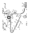
- Figure 1 schematically depicts the various components of an illustrative electrophotographic printing machine incorporating the decurling apparatus of the present invention therein in accordance with one aspect thereof. It will become evident from the following discussion that the decurling apparatus is equally well suited for use in a wide variety of printing machines and is not necessarily limited in its application to the particular embodiment shown herein. In addition, the location of the decurling apparatus, as depicted in the Figure 1 electrophotographic printing machine, may be varied. The decurling apparatus may be positioned intermediate any of the processing stations within the printing machine.
- the decurling apparatus is positioned after the fusing station prior to the catch tray so as to straighten the final copy sheet prior to removal from the printing machine by the operator.
- this location is merely illustrative of the operation of the de-durling apparatus and may be varied.
- the electrophotographic printing machine employs a belt 10 having a photoconductive surface 12 deposited on a conductive substrate 14.
- photoconductive surface 12 comprises a transport layer having small molecules of m-TBD dispersed in a polycarbonate and a generation layer of trigonal selenium.
- Conductive substrate 14 is made preferably from aluminized Mylar which is electrically grounded.
- Belt 10 moves in the direction of arrow 16 to advance successive portions of photoconductive surface 12 through the various processing stations disposed about the path of movement thereof.
- Belt 10 is entrained about stripping roller 18, tension roller 20, and drive roller 22.
- Drive roller 22 is mounted rotatably and in engagement with belt 10.
- Roller 22 is coupled to motor 24 by suitable means such as a belt drive.
- Drive roller 22 includes a pair of opposed, spaced edge guides.
- the edge guides define a space therebetween which determines the desired path of movement of belt 10.
- Belt 10 is maintained in tension by a pair of springs (not shown) resiliently urging tension roller 20 against belt 10 with the desired spring force. Both stripping roller 18 and tension roller 20 are mounted to rotate freely.
- a corona generating device indicated generally by the reference numeral 26, charges photoconductive surface 12 to a relatively high, substantially uniform potential.
- the charged portion of the photoconductive surface 12 is advanced through exposure station B.
- an original document 28 is positioned face- down upon transparent platen 30.
- Lamps 32 flash light rays onto original document 28.
- the light rays reflected from original document 28 are transmitted through lens 34 forming a light image thereof.
- Lens 34 focuses the light image onto the charged portion of photoconductive surface 12 to selectively dissipate the charge thereon. This records an electrostatic latent image on photoconductive surface 12 which corresponds to the informational areas contained within original document 28.
- belt 10 advances the electrostatic latent image recorded on photoconductive surface 12 to development station C.
- a magnetic brush development system indicated generally by the reference numeral 36, transports a developer material into contact with photoconductive surface 12-
- the developer material comprises carrier granules having toner particles adhering triboelectrically thereto.
- Magnetic brush system 36 preferably includes two magnetic brush developer rollers 38 and 40. These developer rollers each advance the developer material into contact with the photoconductive surface 12. Each developer roller forms a chain-like array of developer material extending outwardly therefrom. The toner particles are attracted from the carrier granules to the electrostatic latent image forming a toner powder image on photoconductive surface 12 of belt 10.
- Belt 10 then advances the toner powder image to transfer station D.
- a sheet of support material 42 is moved into contact with the toner powder image.
- the sheet of support material is advanced to transfer station D by a sheet feeding apparatus 44.
- a sheet feeding apparatus 44 includes a feed roll 46 contacting the uppermost sheet of stack 48. Feed roll 46 rotates to advance the uppermost sheet from stack 48 into chute 50. Chute 50 directs the advancing sheet of support material into contact with photoconductive surface 12 in registration with the toner powder image developed thereon. In this way, the toner powder image contacts the advancing sheet of support material at transfer station D.
- Transfer station D includes a corona generating device 52 which sprays ions onto the backside of sheet 42. This attracts the toner powder image from photoconductive surface 12 to sheet 42. After transfer, the sheet continues to move in the direction of arrow 54 onto a conveyor (not shown) which advances the sheet to fusing station E.
- Fusing station E includes a fuser assembly, indicated generally by the reference numeral 56, which permanently affixes the transferred toner powder image to sheet 42.
- a fuser assembly 56 includes a heated fuser roller 58 and a back-up roller 60.
- Sheet 42 passes between fuser roller 58 and back-up roller 60 with the toner powder image contacting fuser roller 58. In this. manner, the toner powder image is heated so as to be permanently affixed to sheet 42.
- sheet 62 guides advancing sheet 42 to the decurling apparatus, indicated generally by the reference numeral 100. At this time, the sheet of support material has undergone numerous processes and very frequently contains undesired curls therein.
- Decurling apparatus 64 bends the sheet of support material so that the sheet material is strained to exhibit plastic characteristics. After passing through de- curling apparatus 100, the sheet of support material is advanced into catch tray 66 for subsequent removal from the printing machine by the operator. The detailed structure of decurling apparatus 100 will be described hereinafter with reference to Figures 2 and 3.
- Cleaning station F includes a pre-clean corona generating device (not shown) and a rotatably mounted fiberous brush 68 in contact with photoconductive surface 12.
- the pre-clean corona generating device neutralizes the charge attracting the particles to the photoconductive surface.
- the particles are then cleaned from photoconductive surface 12 by the rotation of brush 68 in contact therewith.
- a discharge lamp (not shown) floods photoconductive surface 12 with light to dissipate any residual electrostatic charge remaining thereon prior to the charging thereof for the next successive image cycle.
- FIG. 2 depicts an embodiment 100 of the decurler apparatus of the present invention in detail.
- the decurling apparatus 100 features two paths for reverse bending Al (away from image) and TI (toward image) curls (paper path self-determined by direction of fuser curl) and one straight path for flatter papers.
- De-curier 100 requires no adjustment and is capable of reliably handling 13# paper through 110# papers with a wide latitude of moisture content.
- the decurler is cost effective because no belts or stepped rolls for belts are used as in conventional decurlers- As heretofore mentioned, a conventional decurler has a single path and uses multiple bends along the path to accomplish decurling.
- the decurler apparatus 100 incorporates three paper paths. These paper paths take advantage of the fact that fused papers already show clear TI or AI curl tendency in a short distance (about 0.5 inches) from the fuser nip.
- partition baffles 105 and 106 are positioned to guide the lead edges of papers into three paths. As shown in Figure 2, papers (or sheets of any kind) having TI curls are led into a first path defined by guide baffle 101 and partition baffle 106 for reverse bending (Al) by a spring loaded baffle 110 having a small radius and working in conjunction with idler roll 112.
- papers having Ai curls are guided for reverse bending (TI) in a second path defined by guide baffle 102 and partition baffle 105 that directs the papers into curved support 115 and subsequently into spring loaded baffle 111 that has a small radius and works in conjunction with idler roller 113 to decurl the sheets.
- Guide baffles 101 and 102 have end portions adjacent fuser 56 that serve as stripper fingers to insure that severely curled sheets do not continue around either rolls 58 or 60.
- flatter papers leave fuser 56 and are directed by inner surfaces of partition members 105 and 106 into an opening in the center of the decurler apparatus formed by flat surfaces 117 and 118 of support block 116 and 115, respectively. This straight through path directs papers into transport or take away rolls 61 and 62.
- Partition baffles 105 and 106 are wedge baffles or have spring loaded fingers for deflecting sheet material as it leaves fuser 56.
- Reverse bending baffles 110 and 111 are spring loaded for self-adjustment of bending level for thick and thin sheets. Thick sheets will force the baffles to open more so that less bending will act on the sheets.
- the radius of bending baffles 110 and 111 is about 6.4 mm ( 0-25") which is effective for reverse bending.
- Idler rolls 112 and 113 are employed to reduce friction at the bends. Alternatively, as shown in Figure 3, pinch rolls 150 and 160 could be placed at the bends for active driving of sheets through the bends if necessary.
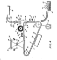
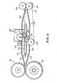
- Figures 4 and 5 depict an embodiment 200 of the decurler apparatus of the present invention in detail in a printing apparatus as shown in and described heretofore in reference to Figure 1.
- the decurling apparatus 200 features two paths for reverse bending Al (away from image) and TI (toward image) curls (paper path self-determined by direction of fuser curl).
- Decurler 200 requires no adjustment and is capable of reliably handling 13# through 110# papers with a wide latitude of moisture content.
- the decurler is cost effective because no belts or stepped rolls for belts are used as in conventional decurlers.
- a conventional decurler has a single path and uses multiple bends along the path to accomplish decurling.
- the decurler apparatus 200 incorporates two paper paths. These paper paths take advantage of the fact that fused papers already show clear TI or AI curl tendency in a short distance (about 0.5 inches) from the fuser nip.
- partition baffle 209 has surfaces 211 and 212 that are positioned to guide the lead edges of papers into two paths. As shown in Figure 5, papers or sheets of any kind having TI are led into a first path defined by guide surface 211 of partition member 209 and baffle 201.
- Baffle 201 also serves as a stripper means to prevent sheets from wrapping around roll 58.
- sheets continue toward an off-set nip formed between rolls 210 and 213.
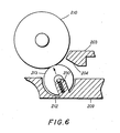
- Drive roll 210 and idler roll 213 drive the curled sheets at a predetermined angle (reverse bending) against a slanted or beveled surface 204 of output baffle 203 and subsequently into the output nip formed by rolls 221 and 222 for transport into output tray 66.
- the baffle 203 with surface 204 reverse bends the sheets for straightening.
- the nip comprises a drive roll 210 and idler roll 213 that is spring loaded by spring 230 against drive roll 210.
- the drive roll drives the sheets at a predetermined angle toward output baffle 203 through a drive force provided by belt 217.
- Belt 217 is connected to provide drive force to rolls 210, 215, 216, and 221.
- sheets having Al curls are guided for reverse bending (TI) in a second path defined by guide 202 and beveled surface 212 of partition member 209 into an off-set nip formed between drive roll 215 and idler roll 214.
- the sheets are driven out of the off-set nip against slanted surface 206 of output baffle 205 for reverse bending and straightening and are straightened into output nip 221, 222 for transport toward catch tray 66.
- a decurler apparatus in which a sheet chooses one of three paths and baffles depending on the amount and direction of the curl.
- the apparatus is designed such that an insignificantly curled sheet passes straight through a center path in the decurler undeflected.
- the baffles located in the other two sheet paths are spring loaded to adjust for degree of curl and paper weight to reverse bend a sheet deflected into either of the two paths for straightening of lightweight or thick sheets.
- a decurler apparatus has been disclosed in which a sheet chooses one of two paths for decurling depending upon the amount and direction of the curl.
- the decurler includes off-set nips from a vertical plane that in combination with output baffles apply reverse bending to the sheets in order to straighten them.
- the nips comprise drive rolls and idler rolls that are biased against the drive rolls.
- the drive rolls drive the sheets at a predetermined angle toward the output baffles.
Landscapes
- Engineering & Computer Science (AREA)
- Mechanical Engineering (AREA)
- Separation, Sorting, Adjustment, Or Bending Of Sheets To Be Conveyed (AREA)
Applications Claiming Priority (4)
| Application Number | Priority Date | Filing Date | Title |
|---|---|---|---|
| US06/718,605 US4632533A (en) | 1985-04-01 | 1985-04-01 | Off-set nip roll decurler |
| US06/718,606 US4591259A (en) | 1985-04-01 | 1985-04-01 | Tri-pass baffle decurler |
| US718605 | 1985-04-01 | ||
| US718606 | 1985-04-01 |
Publications (3)
| Publication Number | Publication Date |
|---|---|
| EP0197722A2 true EP0197722A2 (de) | 1986-10-15 |
| EP0197722A3 EP0197722A3 (en) | 1987-05-13 |
| EP0197722B1 EP0197722B1 (de) | 1990-01-31 |
Family
ID=27109944
Family Applications (1)
| Application Number | Title | Priority Date | Filing Date |
|---|---|---|---|
| EP19860302316 Expired EP0197722B1 (de) | 1985-04-01 | 1986-03-27 | Vorrichtung zum Glätten von Blättern |
Country Status (2)
| Country | Link |
|---|---|
| EP (1) | EP0197722B1 (de) |
| DE (1) | DE3668603D1 (de) |
Cited By (9)
| Publication number | Priority date | Publication date | Assignee | Title |
|---|---|---|---|---|
| FR2623128A1 (fr) * | 1987-11-17 | 1989-05-19 | Gradco Systems Inc | Dispositif de suppression d'ondulation des feuilles de copieurs et d'imprimantes |
| GB2244477A (en) * | 1990-05-16 | 1991-12-04 | Asahi Optical Co Ltd | Correction mechanism for bent recording sheet |
| EP0416896A3 (en) * | 1989-09-05 | 1992-01-15 | Xerox Corporation | Passive, intelligent, sheet decurling system |
| DE4139454A1 (de) * | 1990-11-29 | 1992-06-04 | Ricoh Kk | Vorrichtung zum beseitigen einer rollneigung eines blattes in einer bildaufzeichnungseinrichtung |
| EP0547308A1 (de) * | 1991-12-17 | 1993-06-23 | International Business Machines Corporation | Führungsmittel zum Transport von Blattgut |
| EP0587368A1 (de) * | 1992-09-01 | 1994-03-16 | Lexmark International, Inc. | Selbsteinstellende Vorrichtung zur Beseitigung von Papierkrümmung |
| EP0848352A4 (de) * | 1995-08-31 | 1999-12-22 | Oki Electric Ind Co Ltd | Vorrichtung und verfahren zum behandeln eines mediums |
| EP3352022A1 (de) * | 2017-01-19 | 2018-07-25 | Kabushiki Kaisha Toshiba | Bilderzeugungsvorrichtung und verfahren zum entrollen eines aufzeichnungsmediums |
| CN115891281A (zh) * | 2022-11-21 | 2023-04-04 | 上海纺印利丰印刷包装有限公司 | 一种用于单张烟盒纸的反卷展平装置 |
Family Cites Families (3)
| Publication number | Priority date | Publication date | Assignee | Title |
|---|---|---|---|---|
| US4326915A (en) * | 1979-11-15 | 1982-04-27 | Xerox Corporation | Sheet de-curler |
| US4360356A (en) * | 1980-10-15 | 1982-11-23 | The Standard Register Company | Decurler apparatus |
| US4505695A (en) * | 1983-04-18 | 1985-03-19 | Xerox Corporation | Sheet decurling mechanism |
-
1986
- 1986-03-27 EP EP19860302316 patent/EP0197722B1/de not_active Expired
- 1986-03-27 DE DE8686302316T patent/DE3668603D1/de not_active Expired - Fee Related
Cited By (14)
| Publication number | Priority date | Publication date | Assignee | Title |
|---|---|---|---|---|
| GB2212481A (en) * | 1987-11-17 | 1989-07-26 | Gradco Systems Inc | Apparatus for removing curl from sheets of paper |
| FR2623128A1 (fr) * | 1987-11-17 | 1989-05-19 | Gradco Systems Inc | Dispositif de suppression d'ondulation des feuilles de copieurs et d'imprimantes |
| EP0416896A3 (en) * | 1989-09-05 | 1992-01-15 | Xerox Corporation | Passive, intelligent, sheet decurling system |
| US5230691A (en) * | 1990-05-16 | 1993-07-27 | Asahi Kogaku Kogyo Kabushiki Kaisha | Correction mechanism for bent recording sheet |
| GB2244477A (en) * | 1990-05-16 | 1991-12-04 | Asahi Optical Co Ltd | Correction mechanism for bent recording sheet |
| GB2244477B (en) * | 1990-05-16 | 1994-09-21 | Asahi Optical Co Ltd | Correction mechanism for bent recording sheet |
| DE4139454A1 (de) * | 1990-11-29 | 1992-06-04 | Ricoh Kk | Vorrichtung zum beseitigen einer rollneigung eines blattes in einer bildaufzeichnungseinrichtung |
| EP0547308A1 (de) * | 1991-12-17 | 1993-06-23 | International Business Machines Corporation | Führungsmittel zum Transport von Blattgut |
| US5301618A (en) * | 1991-12-17 | 1994-04-12 | International Business Machines Corporation | Guide means for conveying sheet-shaped media |
| EP0587368A1 (de) * | 1992-09-01 | 1994-03-16 | Lexmark International, Inc. | Selbsteinstellende Vorrichtung zur Beseitigung von Papierkrümmung |
| EP0848352A4 (de) * | 1995-08-31 | 1999-12-22 | Oki Electric Ind Co Ltd | Vorrichtung und verfahren zum behandeln eines mediums |
| US6092798A (en) * | 1995-08-31 | 2000-07-25 | Oki Electric Industry Co., Ltd. | Ticket issuing apparatus |
| EP3352022A1 (de) * | 2017-01-19 | 2018-07-25 | Kabushiki Kaisha Toshiba | Bilderzeugungsvorrichtung und verfahren zum entrollen eines aufzeichnungsmediums |
| CN115891281A (zh) * | 2022-11-21 | 2023-04-04 | 上海纺印利丰印刷包装有限公司 | 一种用于单张烟盒纸的反卷展平装置 |
Also Published As
| Publication number | Publication date |
|---|---|
| DE3668603D1 (de) | 1990-03-08 |
| EP0197722B1 (de) | 1990-01-31 |
| EP0197722A3 (en) | 1987-05-13 |
Similar Documents
| Publication | Publication Date | Title |
|---|---|---|
| US4591259A (en) | Tri-pass baffle decurler | |
| US4632533A (en) | Off-set nip roll decurler | |
| US5202737A (en) | Method and apparatus for decurling sheets in a copying device | |
| US4326915A (en) | Sheet de-curler | |
| US5555083A (en) | Decurler apparatus for reducing cross curl in sheets | |
| US4505695A (en) | Sheet decurling mechanism | |
| US4744555A (en) | Sheet transport and registration apparatus | |
| US5565971A (en) | Pivotal bi-directional decurler | |
| US5288062A (en) | High capacity compiler with vertically adjustable sheet discharge and acquire means | |
| US5123895A (en) | Passive, intelligent, sheet decurling system | |
| US4040616A (en) | Sheet turn around/inverter | |
| US5350168A (en) | Corrugated fang for multi media feeder | |
| GB2082551A (en) | Laterally offsetting and stacking sheets | |
| JPS6227276A (ja) | ナイフ式フオルダ | |
| US4234305A (en) | Transfer sheet guiding device | |
| EP0197722B1 (de) | Vorrichtung zum Glätten von Blättern | |
| US4487407A (en) | Trail edge copy registration system | |
| US5211388A (en) | Retard roll enhancement | |
| US4359219A (en) | Direct control paddle wheel | |
| EP0425249B1 (de) | Kopiergeräte mit Systemen zum seitlichen Ausrichten | |
| US4364550A (en) | Corrugation venturi paper feeder | |
| USRE33843E (en) | Sheet transport and registration apparatus | |
| US4571054A (en) | Post-fuser copy sheet decurler | |
| EP0929013B1 (de) | Führung zur Beseitigung von Wellen vor Schmelzfixiervorrichtung | |
| US4662625A (en) | Decorrugating paper transport |
Legal Events
| Date | Code | Title | Description |
|---|---|---|---|
| PUAI | Public reference made under article 153(3) epc to a published international application that has entered the european phase |
Free format text: ORIGINAL CODE: 0009012 |
|
| AK | Designated contracting states |
Kind code of ref document: A2 Designated state(s): DE FR GB |
|
| PUAL | Search report despatched |
Free format text: ORIGINAL CODE: 0009013 |
|
| AK | Designated contracting states |
Kind code of ref document: A3 Designated state(s): DE FR GB |
|
| 17P | Request for examination filed |
Effective date: 19871028 |
|
| 17Q | First examination report despatched |
Effective date: 19881123 |
|
| GRAA | (expected) grant |
Free format text: ORIGINAL CODE: 0009210 |
|
| AK | Designated contracting states |
Kind code of ref document: B1 Designated state(s): DE FR GB |
|
| REF | Corresponds to: |
Ref document number: 3668603 Country of ref document: DE Date of ref document: 19900308 |
|
| ET | Fr: translation filed | ||
| PLBE | No opposition filed within time limit |
Free format text: ORIGINAL CODE: 0009261 |
|
| STAA | Information on the status of an ep patent application or granted ep patent |
Free format text: STATUS: NO OPPOSITION FILED WITHIN TIME LIMIT |
|
| 26N | No opposition filed | ||
| PGFP | Annual fee paid to national office [announced via postgrant information from national office to epo] |
Ref country code: FR Payment date: 20010313 Year of fee payment: 16 |
|
| PGFP | Annual fee paid to national office [announced via postgrant information from national office to epo] |
Ref country code: DE Payment date: 20010319 Year of fee payment: 16 |
|
| PGFP | Annual fee paid to national office [announced via postgrant information from national office to epo] |
Ref country code: GB Payment date: 20010321 Year of fee payment: 16 |
|
| REG | Reference to a national code |
Ref country code: GB Ref legal event code: IF02 |
|
| PG25 | Lapsed in a contracting state [announced via postgrant information from national office to epo] |
Ref country code: GB Free format text: LAPSE BECAUSE OF NON-PAYMENT OF DUE FEES Effective date: 20020327 |
|
| PG25 | Lapsed in a contracting state [announced via postgrant information from national office to epo] |
Ref country code: DE Free format text: LAPSE BECAUSE OF NON-PAYMENT OF DUE FEES Effective date: 20021001 |
|
| GBPC | Gb: european patent ceased through non-payment of renewal fee |
Effective date: 20020327 |
|
| PG25 | Lapsed in a contracting state [announced via postgrant information from national office to epo] |
Ref country code: FR Free format text: LAPSE BECAUSE OF NON-PAYMENT OF DUE FEES Effective date: 20021129 |
|
| REG | Reference to a national code |
Ref country code: FR Ref legal event code: ST |