EP0197624A1 - Conductor cable - Google Patents
Conductor cable Download PDFInfo
- Publication number
- EP0197624A1 EP0197624A1 EP86300439A EP86300439A EP0197624A1 EP 0197624 A1 EP0197624 A1 EP 0197624A1 EP 86300439 A EP86300439 A EP 86300439A EP 86300439 A EP86300439 A EP 86300439A EP 0197624 A1 EP0197624 A1 EP 0197624A1
- Authority
- EP
- European Patent Office
- Prior art keywords
- conductor cable
- die
- ply
- round wire
- flat conductor
- Prior art date
- Legal status (The legal status is an assumption and is not a legal conclusion. Google has not performed a legal analysis and makes no representation as to the accuracy of the status listed.)
- Granted
Links
Images

Classifications
-
- H—ELECTRICITY
- H01—ELECTRIC ELEMENTS
- H01B—CABLES; CONDUCTORS; INSULATORS; SELECTION OF MATERIALS FOR THEIR CONDUCTIVE, INSULATING OR DIELECTRIC PROPERTIES
- H01B7/00—Insulated conductors or cables characterised by their form
- H01B7/08—Flat or ribbon cables
- H01B7/0838—Parallel wires, sandwiched between two insulating layers
-
- Y—GENERAL TAGGING OF NEW TECHNOLOGICAL DEVELOPMENTS; GENERAL TAGGING OF CROSS-SECTIONAL TECHNOLOGIES SPANNING OVER SEVERAL SECTIONS OF THE IPC; TECHNICAL SUBJECTS COVERED BY FORMER USPC CROSS-REFERENCE ART COLLECTIONS [XRACs] AND DIGESTS
- Y10—TECHNICAL SUBJECTS COVERED BY FORMER USPC
- Y10T—TECHNICAL SUBJECTS COVERED BY FORMER US CLASSIFICATION
- Y10T428/00—Stock material or miscellaneous articles
- Y10T428/24—Structurally defined web or sheet [e.g., overall dimension, etc.]
- Y10T428/24628—Nonplanar uniform thickness material
- Y10T428/24669—Aligned or parallel nonplanarities
-
- Y—GENERAL TAGGING OF NEW TECHNOLOGICAL DEVELOPMENTS; GENERAL TAGGING OF CROSS-SECTIONAL TECHNOLOGIES SPANNING OVER SEVERAL SECTIONS OF THE IPC; TECHNICAL SUBJECTS COVERED BY FORMER USPC CROSS-REFERENCE ART COLLECTIONS [XRACs] AND DIGESTS
- Y10—TECHNICAL SUBJECTS COVERED BY FORMER USPC
- Y10T—TECHNICAL SUBJECTS COVERED BY FORMER US CLASSIFICATION
- Y10T428/00—Stock material or miscellaneous articles
- Y10T428/31504—Composite [nonstructural laminate]
- Y10T428/31721—Of polyimide
-
- Y—GENERAL TAGGING OF NEW TECHNOLOGICAL DEVELOPMENTS; GENERAL TAGGING OF CROSS-SECTIONAL TECHNOLOGIES SPANNING OVER SEVERAL SECTIONS OF THE IPC; TECHNICAL SUBJECTS COVERED BY FORMER USPC CROSS-REFERENCE ART COLLECTIONS [XRACs] AND DIGESTS
- Y10—TECHNICAL SUBJECTS COVERED BY FORMER USPC
- Y10T—TECHNICAL SUBJECTS COVERED BY FORMER US CLASSIFICATION
- Y10T428/00—Stock material or miscellaneous articles
- Y10T428/31504—Composite [nonstructural laminate]
- Y10T428/31855—Of addition polymer from unsaturated monomers
- Y10T428/31931—Polyene monomer-containing
Definitions
- This invention relates generally to an electrical conductor cable having multiple conductor wires for carrying a plurality of different electrical signals. More particularly, this invention relates to an improved lightweight and pliable flat conductor cable designed for long-term use substantially without degradation or failure due to exposure to ultraviolet radiation or temperature extremes.
- Electrical conductor cables typically include a plurality of elongated conductor elements for carrying a plurality of electrical signals, for example, between components of electronic equipment as in a computer system or the like.
- the conductor elements commonly comprise elongated wires of a conductive material, such as copper or the like, having a generally round cross-sectional shape and individually jacketed by an appropriate insulation material.
- the plurality of insulated wires are assembled into generally parallel relation and collectively retained within an outer wrap of insulation material to form the conductor cable.
- the conductor wires are bundled together to form a cable having a generally round cross-sectional shape with sufficient flexibility and compactness for use in a wide range of applications.
- the conductor wires are assembled into a generally coplanar or flat cable configuration.
- the insulation material encasing the conductor wires preferably comprises a specialized material which will maintain the desired level of flexibility and dielectric properties during use in outer space.
- one dielectric material found to be especially suited for use in an outer space environment without significant degradation comprises a polyimide sheet material manufactured and sold by E. I. du Pont de Nemours and Company, Wilmington, Delaware, under the name Kapton. More specifically, Kapton polyimide sheet material is a lightweight and highly pliable substance possessing excellent dielectric properties and adequate tensile strength for use as an insulation material for electrical conductor elements. Moreover, Kapton sheet material is highly resistant to physical degradation in an outer space environment including, for example, resistance to embrittlement from exposure to ultraviolet radiation or from outgassing in a vacuum and resistance to degradation from exposure to temperature extremes within a range typically encountered in outer space. However, Kapton sheet material resists conventional thermal forming and shaping processes and thus heretofore has not been formed into a configuration satisfactory for use as a flat cable insulation material.
- flat conductor cables have been constructed to include a plurality of round wire conductors insulated individually by spirally wrapped strips of Kapton sheet material, with the thus-wrapped conductors being retained in a flat cable configuration within an outer jacket typically of a molded polyester plastic or the like.
- the outer jacket is subject to degradation in an outer space environment thereby providing significant potential for cable failure over a period of time.
- the use of spirally wrapped Kapton strips particularly in addition to the outer jacket of a different material undesirably and unacceptably increases the overall thickness and stiffness of the flat conductor cable.
- an improved flat conductor cable includes a plurality of round wire conductors encased within generally parallel formed channels defined cooperatively by bonded upper and lower plies of polyimide insulation sheet material, particularly such as Kapton film. At least one of the Kapton film plies is preformed preferably by a thermal forming process to include a generally parallel plurality of spaced, open-topped channels for individually receiving the round wire conductors. The other Kapton film ply is then bonded by a suitable adhesive onto the preformed ply to close the open-topped channels and form the lightweight pliable flat conductor cable.
- a lower ply of Kapton film is placed over the face of a forming die having a plurality of elongated, generally parallel grooves therein.
- a plurality of elongated die bars of a heat conductive material are inserted one at a time into adjacent forming die grooves to press and seat the lower Kapton film ply into conformance with said grooves.
- An upper platen is placed over the forming dies to form a closed die assembly retaining the die bars within the grooves while the lower Kapton film ply is subjected to a thermal forming step at about 850 0 F to about 900° F for about 30 minutes, resulting in thermal forming of said lower ply to include a plurality of open-topped and spaced parallel channels.
- the upper platen and the die bars are then removed to expose the lower Kapton film ply and the channels formed therein.
- Round wire conductors such as ' flexible braided copper wire or the like, are seated individually within the open-topped channels while the lower ply remains seated upon the forming die.
- An adhesive substance preferably in the form of a thin sheet of a thermal setting nitrile adhesive or the like is placed over the lower Kapton film ply and the seated conductors, followed by placement of the upper Kapton film ply and the upper platen.
- the thus-reassembled die assembly is subjected to a thermal bonding step, for example, by exposure to a temperature of about 350 0 F for about 5 .minutes while maintaining, the upper and lower Kapton film plies in intimate contact with the adhesive sheet.
- the resultant flat conductor cable is then be stripped from the die assembly ready for use or for appropriate connection to an additional conductor cable segment to form a cable of increased length.
- an improved conductor cable referred to generally by the reference numeral 10 has an elongated and generally flat configuration supporting in parallel array a plurality of generally coplanar round wire conductors 12. These round wire conductors 12 are supported within preformed channels between a lower ply 14 and an upper ply 16 of a polyimide insulation sheet material selected for resistance to degradation upon exposure to ultraviolet radiation and temperature extremes as encountered, for example, in an outer space environment.
- the improved flat conduct cable 10 of the present invention advantageously provides a relatively thin and thus compact cable geometry for interconnecting components of electronic equipment, for example, as in a computer system or the like, with substantially minimum volumetric space requirements.
- the round wire conductors 12 are supported in spaced, electrically insulated relation by the lower and upper plies 14 and 16, which, according to the apparatus and process of the invention, are advantageously formed from polyimide film or sheet material manufactured and sold by E. I. du Pont de Nemours and Company, Wilmington, Delaware, under the name Kapton.
- This Kapton film material is lightweight and possesses highly desirable pliability characteristics with excellent dielectric properties.
- Kapton film is highly resistant to degradation, such as embrittlement, when subjected to an outer space environment including relatively high exposure to ultraviolet radiation, exposure to temperature extremes, and prolonged exposure to vacuum.
- the flat conductor cable 10 of the present invention and a preferred process for the manufacture thereof are shown in more detail in FIGS. 2-8. More particularly, with specific reference to FIGS. 2-4, the lower ply 14 of the Kapton film material is initially preformed within a die assembly 18 to include a longitudinally elongated plurality of spaced parallel channels 20 of open-topped configuration for subsequent reception of the round wire conductors 12, as will be described.
- This lower Kapton film ply is provided in lightweight sheet form having a thickness within the range of about 0.5 mil to about 5.0 mil, with a preferred sheet thickness being on the order of about 1.0 mil.
- the lower ply 14 is placed over an elongated forming die 22 having an upwardly presented face shaped to define a longitudinally elongated plurality of upwardly open grooves 24 shown in the illustrative drawings to have a generally rectangular cross-sectional shape.
- the lower Kapton film ply 14 is pressed or otherwise drawn into conformance with the upper face of the forming die 22 whereby said lower ply 14 is preformed to include the elongated open-topped channels 20.
- conformance is achieved by placing elongated die bars 26 individually into the forming die grooves 24 to press the lower ply 14 into intimate seated relation within and following the contour of the grooves 24. As shown best in FIG. 3, these die bars 26 are inserted one at a time in a regular or serial fashion by placing a subsequent die bar into a forming die groove 24 adjacent an already- inserted die bar to prevent significant stretching of . the Kapton film material which could otherwise cause undesired film tearing.
- the die bars can be inserted into adjacent grooves beginning at the transverse center of the forming die and then proceeding outwardly on opposite sides thereof, as viewed in FIG. 3, or the die bars can be placed into the grooves beginning at one side of the forming die.
- the lower Kapton film ply 14 has sufficient transverse width to span the width of the forming die 22 when pressed by the die bars 26 into conformance with the forming die grooves 24.
- the die assembly 18 is then subjected to a thermal forming step by appropriate exposure to an elevated temperature causing the lower ply to assume a thermal set in conformance with the geometry of the forming die face.
- the Kapton film ply having a thickness within the range of about 0.5 mil to about 5.0 mil will assume the desired thermal set when exposed to elevated temperature in the range of about 825° F to about 950 0 F, and preferably within the range of about 850° F to about 9000 F, for at least about 30 minutes, with only light pressure maintaining the die assembly in a closed state being required. Exposure of a temperature above this range tends to cause undesired crystalization of the Kapton film, whereas exposure to a temperature below about 850 0 F fails to produce the desired thermal set.
- the thermal forming step is enhanced by constructing the die assembly 18 including the die bars 26 from a material having high thermal conductivity, such as aluminum, and further by shaping the die bars 26 for generally mating reception into the forming die grooves 24 to insure intimate heat transfer contact with the lower film ply 14.
- a material having high thermal conductivity such as aluminum
- these round wire conductors 12 are formed from a relatively soft braided wire of a material such as copper or aluminum wire having a high degree of flexibility and a diametric size generally corresponding with the depth of the channels 20.
- an adhesive substance is then placed over the lower Kapton film ply 14 and the conductors 12 seated within the preformed channels 20.
- one preferred adhesive substance comprises a relatively thin sheet of a thermal setting nitrile adhesive 30 having a size and shape generally corresponding with the length and width of the forming die 22.
- the upper Kapton film ply 16 which also has a length and width generally corresponding to the forming die 22, is then placed over the nitrile adhesive sheet 30 followed by reassembly of the upper platen 28 with the forming die 22 with sufficient pressure to maintain the lower and upper plies 14 and 16 in intimate contact with the adhesive sheet 30.
- the thus-reassembled die assembly as viewed in FIG.
- a thermal bonding step including a temperature sufficient to bond the plies 14 and 16 together via the adhesive sheet 30.
- a thermal forming step comprising exposure of the die assembly 18 to a temperature of about 350 0 F for a time period of about 5 minutes is sufficient to provide a highly satisfactory thermal bond.
- the thus-formed flat conductor cable 10 having the round wire conductors 12 encased therein can then be stripped from the die assembly 18 by appropriate removal from the upper platen 28 and the lower forming die 22.
- the resultant conductor cable 10 cooperatively supports and insulates the conductors 12 separately within the channels 20 to permit independent transmission of electrical signals via said conductors.
- the Kapton film plies 14 and 16 are lightweight and possess a high degree of flexibility or pliability for versatile use in a wide variety of conductor cable environments.
- the improved conductor cable 10 is particularly suited to use in an outer space environment, since the Kapton film material is highly resistant to degradation from exposure to ultraviolet light or prolonged exposure to a vacuum. Moreover, the Kapton film material maintains its desired high pliability without embrittlement or ply separation throughout a wide range of temperature extremes typically encountered within an outer space environment.
- the overall length of the improved conductor cable 10 manufactured in accordance with the process depicted in FIGS. 2-8 is not limited to the longitudinal length of the forming die 22, nor is it necessary to physically splice adjacent ends of the round wire conductors 12 to provide a cable of increased overall length.
- the Kapton film plies encasing the conductors 12 can be installed in segments with misaligned, overlapping ends in association with continuous or uninterrupted conductors 12 to provide a conductor cable of virtually any desired overall length.
- round wire conductors 12 can be seated as described previously within preformed channels 20 of a lower Kapton film ply 14, wherein the round wire conductors 12 project substantially beyond the underlying aligned ends of the lower ply 14 and the forming die 22.
- the preformed lower ply 14 and the seated conductors 12 can then be covered by a suitable adhesive substance and an overlying upper Kapton film ply 16, followed by placement of the upper platen 28, generally as described above, but with the upper ply 16 and upper platen 28 terminating in longitudinal misalignment relative to the lower ply 14.
- a thermal bonding step as previously described can then be performed to provide a conductor cable segment with longitudinally misaligned lower and upper plies 14 and 16.
- the thus-formed cable segment is then positioned in end-to-end relation with an adjacent lower Kapton film ply 14' having preformed channels 20' and carried by an adjacent identical forming die 22 to permit seating of the conductors 12 within the aligned channels 20', as shown in FIG. 10.
- a second upper ply 16' and associated adhesive substance are then placed in overlying relation with the exposed portions of the lower plies 14 and 14', as viewed in FIG. 11, and this second upper ply 16 1 is covered by the upper platen 28 for performance of a subsequent thermal bonding step.
- An elongated conductor cable is thus formed having lower Kapton film plies 14 and 14' and upper film plies 16 and 16' disposed respectively in end-to-end relation but with the upper and lower ply ends longitudinally misaligned relative to each other.
- the conductor cable segments are thus interconnected in a secure and stable manner while permitting use of continuous round wire conductors 12 thereby permitting manufacture of a conductor cable of any desired length.
Abstract
Description
- This invention relates generally to an electrical conductor cable having multiple conductor wires for carrying a plurality of different electrical signals. More particularly, this invention relates to an improved lightweight and pliable flat conductor cable designed for long-term use substantially without degradation or failure due to exposure to ultraviolet radiation or temperature extremes.
- Electrical conductor cables, sometimes referred as wiring harnesses, typically include a plurality of elongated conductor elements for carrying a plurality of electrical signals, for example, between components of electronic equipment as in a computer system or the like. The conductor elements commonly comprise elongated wires of a conductive material, such as copper or the like, having a generally round cross-sectional shape and individually jacketed by an appropriate insulation material. The plurality of insulated wires are assembled into generally parallel relation and collectively retained within an outer wrap of insulation material to form the conductor cable. In accordance with one common cable geometry, the conductor wires are bundled together to form a cable having a generally round cross-sectional shape with sufficient flexibility and compactness for use in a wide range of applications. However, in some cable installation applications, particularly such as a spacecraft environment, substantially increased cable flexibility and reduced cable thickness can be highly desirable to accommodate volumetric size constraints. In such applications, the conductor wires are assembled into a generally coplanar or flat cable configuration. Moreover, in a spacecraft environment, the insulation material encasing the conductor wires preferably comprises a specialized material which will maintain the desired level of flexibility and dielectric properties during use in outer space.
- In the past, one dielectric material found to be especially suited for use in an outer space environment without significant degradation comprises a polyimide sheet material manufactured and sold by E. I. du Pont de Nemours and Company, Wilmington, Delaware, under the name Kapton. More specifically, Kapton polyimide sheet material is a lightweight and highly pliable substance possessing excellent dielectric properties and adequate tensile strength for use as an insulation material for electrical conductor elements. Moreover, Kapton sheet material is highly resistant to physical degradation in an outer space environment including, for example, resistance to embrittlement from exposure to ultraviolet radiation or from outgassing in a vacuum and resistance to degradation from exposure to temperature extremes within a range typically encountered in outer space. However, Kapton sheet material resists conventional thermal forming and shaping processes and thus heretofore has not been formed into a configuration satisfactory for use as a flat cable insulation material.
- More particularly, flat conductor cables have been constructed to include a plurality of round wire conductors insulated individually by spirally wrapped strips of Kapton sheet material, with the thus-wrapped conductors being retained in a flat cable configuration within an outer jacket typically of a molded polyester plastic or the like. However, the outer jacket is subject to degradation in an outer space environment thereby providing significant potential for cable failure over a period of time. Moreover, the use of spirally wrapped Kapton strips particularly in addition to the outer jacket of a different material undesirably and unacceptably increases the overall thickness and stiffness of the flat conductor cable.
- Alternative flat conductor cables have been developed using Kapton sheet material for insulating thin ribbon-like conductor elements in lieu of conventional round wire conductors, as described above. In such alternative cables, a plurality of the ribbon-like conductor elements are retained in spaced, generally parallel relation between two plies of Kapton sheet material bonded together with an appropriate adhesive. While such cables possess a substantially minimum thickness and further have exhibited a high degree of longevity in outer space use, each of the plurality of thin conductor elements must have a substantial width to provide the necessary current-carrying capacity. As a result, the overall width of the flat conductor cable becomes unduly large and unacceptable for many installation applications.
- There exists, therefore, a significant need for an improved flat conductor cable of the type having a plurality of round wire conductors, wherein the round wire conductors are encased by formed plies of Kapton sheet material for optimum flexibility, compactness, and longevity in an outer space environment. The present invention fulfills these needs and provides further related advantages.
- In accordance with the invention, an improved flat conductor cable includes a plurality of round wire conductors encased within generally parallel formed channels defined cooperatively by bonded upper and lower plies of polyimide insulation sheet material, particularly such as Kapton film. At least one of the Kapton film plies is preformed preferably by a thermal forming process to include a generally parallel plurality of spaced, open-topped channels for individually receiving the round wire conductors. The other Kapton film ply is then bonded by a suitable adhesive onto the preformed ply to close the open-topped channels and form the lightweight pliable flat conductor cable.
- In a preferred form of the invention, and in accordance with a preferred process for forming the invention, a lower ply of Kapton film is placed over the face of a forming die having a plurality of elongated, generally parallel grooves therein. A plurality of elongated die bars of a heat conductive material are inserted one at a time into adjacent forming die grooves to press and seat the lower Kapton film ply into conformance with said grooves. An upper platen is placed over the forming dies to form a closed die assembly retaining the die bars within the grooves while the lower Kapton film ply is subjected to a thermal forming step at about 8500 F to about 900° F for about 30 minutes, resulting in thermal forming of said lower ply to include a plurality of open-topped and spaced parallel channels.
- The upper platen and the die bars are then removed to expose the lower Kapton film ply and the channels formed therein. Round wire conductors, such as 'flexible braided copper wire or the like, are seated individually within the open-topped channels while the lower ply remains seated upon the forming die. An adhesive substance, preferably in the form of a thin sheet of a thermal setting nitrile adhesive or the like is placed over the lower Kapton film ply and the seated conductors, followed by placement of the upper Kapton film ply and the upper platen. The thus-reassembled die assembly is subjected to a thermal bonding step, for example, by exposure to a temperature of about 3500 F for about 5 .minutes while maintaining, the upper and lower Kapton film plies in intimate contact with the adhesive sheet. The resultant flat conductor cable is then be stripped from the die assembly ready for use or for appropriate connection to an additional conductor cable segment to form a cable of increased length.
- Other features and advantages of the present invention will become more apparent from the following detailed description, taken in conjunction with the accompanying drawings, which illustrate, by way of example, the principles of the invention.
- The accompanying drawings illustrate the invention. In such drawings:
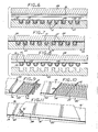
- FIGURE 1 is a fragmented perspective view illustrating a flat conductor cable embodying the novel features of the invention;
- FIGURE 2 is an enlarged fragmented exploded perspective view illustrating a die assembly for preforming a lower Kapton film ply for use in the conductor cable of the invention;
- FIGURE 3 is an enlarged transverse vertical sectional view taken generally along the line 3-3 of FIG. 2 and illustrating seating of the lower Kapton film ply into grooves in the face of a forming die comprising a portion of the die assembly;
- FIGURE 4 is a transverse vertical sectional view generally similar to FIG. 3 but illustrating the die assembly in a closed state during a thermal forming step;
- FIGURE 5 is a transverse vertical sectional view similar to FIG. 3 but illustrating removal of die bars from the forming die grooves subsequent to the thermal forming step;
- FIGURE 6 is a transverse vertical sectional view similar to FIG. 3 but illustrating reassembly of the die assembly in association with round wire conductors and an upper Kapton film ply;
- FIGURE 7 is a transverse vertical sectional view generally similar to FIG. 6 but illustrating the die assembly in a closed state during a thermal bonding step;
- FIGURE 8 is an exploded transverse sectional view generally similar to FIG. 6 but illustrating removal of the flat conductor cable from the die assembly;
- FIGURE 9 is a fragmented perspective view illustrating formation of a flat conductor cable segment designed for connection with an adjacent cable segment to form a conductor cable of increased length;
- FIGURE 10 is a fragmented perspective view similar to FIG. 9 and illustrating a subsequent step in the connection of conductor cable segments; and
- FIGURE 11 is a fragmented perspective view illustrating a further step in the connection of conductor cable segments.
- As shown in the accompanying drawings, an improved conductor cable referred to generally by the
reference numeral 10 has an elongated and generally flat configuration supporting in parallel array a plurality of generally coplanarround wire conductors 12. Theseround wire conductors 12 are supported within preformed channels between alower ply 14 and anupper ply 16 of a polyimide insulation sheet material selected for resistance to degradation upon exposure to ultraviolet radiation and temperature extremes as encountered, for example, in an outer space environment. - The improved
flat conduct cable 10 of the present invention advantageously provides a relatively thin and thus compact cable geometry for interconnecting components of electronic equipment, for example, as in a computer system or the like, with substantially minimum volumetric space requirements. Theround wire conductors 12 are supported in spaced, electrically insulated relation by the lower andupper plies - The
flat conductor cable 10 of the present invention and a preferred process for the manufacture thereof are shown in more detail in FIGS. 2-8. More particularly, with specific reference to FIGS. 2-4, thelower ply 14 of the Kapton film material is initially preformed within adie assembly 18 to include a longitudinally elongated plurality of spacedparallel channels 20 of open-topped configuration for subsequent reception of theround wire conductors 12, as will be described. This lower Kapton film ply is provided in lightweight sheet form having a thickness within the range of about 0.5 mil to about 5.0 mil, with a preferred sheet thickness being on the order of about 1.0 mil. Thelower ply 14 is placed over an elongated forming die 22 having an upwardly presented face shaped to define a longitudinally elongated plurality of upwardlyopen grooves 24 shown in the illustrative drawings to have a generally rectangular cross-sectional shape. - The lower Kapton
film ply 14 is pressed or otherwise drawn into conformance with the upper face of the forming die 22 whereby saidlower ply 14 is preformed to include the elongated open-topped channels 20. In the preferred process, such conformance is achieved by placingelongated die bars 26 individually into the formingdie grooves 24 to press thelower ply 14 into intimate seated relation within and following the contour of thegrooves 24. As shown best in FIG. 3, these diebars 26 are inserted one at a time in a regular or serial fashion by placing a subsequent die bar into a formingdie groove 24 adjacent an already- inserted die bar to prevent significant stretching of . the Kapton film material which could otherwise cause undesired film tearing. Accordingly, the die bars can be inserted into adjacent grooves beginning at the transverse center of the forming die and then proceeding outwardly on opposite sides thereof, as viewed in FIG. 3, or the die bars can be placed into the grooves beginning at one side of the forming die. In either case, the lower Kapton film ply 14 has sufficient transverse width to span the width of the formingdie 22 when pressed by the die bars 26 into conformance with the forming diegrooves 24. - When the die bars 26 are inserted, an
upper platen 28 forming a portion of thedie assembly 18 is placed over thelower ply 14 and the inserted die bars 26, as viewed in FIG. 4. In accordance with the preferred process of the invention, thedie assembly 18 is then subjected to a thermal forming step by appropriate exposure to an elevated temperature causing the lower ply to assume a thermal set in conformance with the geometry of the forming die face. In this regard, it has been found that the Kapton film ply having a thickness within the range of about 0.5 mil to about 5.0 mil will assume the desired thermal set when exposed to elevated temperature in the range of about 825° F to about 9500 F, and preferably within the range of about 850° F to about 9000 F, for at least about 30 minutes, with only light pressure maintaining the die assembly in a closed state being required. Exposure of a temperature above this range tends to cause undesired crystalization of the Kapton film, whereas exposure to a temperature below about 8500 F fails to produce the desired thermal set. Moreover, the thermal forming step is enhanced by constructing thedie assembly 18 including the die bars 26 from a material having high thermal conductivity, such as aluminum, and further by shaping the die bars 26 for generally mating reception into the forming diegrooves 24 to insure intimate heat transfer contact with thelower film ply 14. - Subsequent to the thermal forming step, the
upper platen 28 is removed to expose the preformed lower Kapton film ply 14 and the plurality of die bars 26, thereby permitting removal of the die bars as shown in FIG. 5. The preformedchannels 20 in thelower ply 14 are thus exposed to permit individual placement of theround wire conductors 20 into those channels, as shown in FIG. 6. Conveniently, theseround wire conductors 12 are formed from a relatively soft braided wire of a material such as copper or aluminum wire having a high degree of flexibility and a diametric size generally corresponding with the depth of thechannels 20. - An adhesive substance is then placed over the lower Kapton film ply 14 and the
conductors 12 seated within the preformedchannels 20. Although the specific type and form of adhesive substance may vary as understood by those skilled in the art, one preferred adhesive substance comprises a relatively thin sheet of a thermalsetting nitrile adhesive 30 having a size and shape generally corresponding with the length and width of the formingdie 22. The upper Kapton film ply 16, which also has a length and width generally corresponding to the formingdie 22, is then placed over the nitrileadhesive sheet 30 followed by reassembly of theupper platen 28 with the formingdie 22 with sufficient pressure to maintain the lower andupper plies adhesive sheet 30. The thus-reassembleddie assembly 18, as viewed in FIG. 7, is ready for a thermal bonding step including a temperature sufficient to bond theplies adhesive sheet 30. In this regard, when a sheet of nitrile adhesive material is used, a thermal forming step comprising exposure of thedie assembly 18 to a temperature of about 3500 F for a time period of about 5 minutes is sufficient to provide a highly satisfactory thermal bond. - As shown in FIG. 8, following the thermal bonding step, the thus-formed
flat conductor cable 10 having theround wire conductors 12 encased therein can then be stripped from thedie assembly 18 by appropriate removal from theupper platen 28 and the lower formingdie 22. Theresultant conductor cable 10 cooperatively supports and insulates theconductors 12 separately within thechannels 20 to permit independent transmission of electrical signals via said conductors. The Kapton film plies 14 and 16 are lightweight and possess a high degree of flexibility or pliability for versatile use in a wide variety of conductor cable environments. Theimproved conductor cable 10 is particularly suited to use in an outer space environment, since the Kapton film material is highly resistant to degradation from exposure to ultraviolet light or prolonged exposure to a vacuum. Moreover, the Kapton film material maintains its desired high pliability without embrittlement or ply separation throughout a wide range of temperature extremes typically encountered within an outer space environment. - The overall length of the
improved conductor cable 10 manufactured in accordance with the process depicted in FIGS. 2-8 is not limited to the longitudinal length of the formingdie 22, nor is it necessary to physically splice adjacent ends of theround wire conductors 12 to provide a cable of increased overall length. Instead, as shown in FIGS. 9-11, the Kapton film plies encasing theconductors 12 can be installed in segments with misaligned, overlapping ends in association with continuous oruninterrupted conductors 12 to provide a conductor cable of virtually any desired overall length. - More particularly, as depicted by way of example in FIG. 9,
round wire conductors 12 can be seated as described previously within preformedchannels 20 of a lower Kapton film ply 14, wherein theround wire conductors 12 project substantially beyond the underlying aligned ends of thelower ply 14 and the formingdie 22. The preformedlower ply 14 and the seatedconductors 12 can then be covered by a suitable adhesive substance and an overlying upper Kapton film ply 16, followed by placement of theupper platen 28, generally as described above, but with theupper ply 16 andupper platen 28 terminating in longitudinal misalignment relative to thelower ply 14. A thermal bonding step as previously described can then be performed to provide a conductor cable segment with longitudinally misaligned lower andupper plies - The thus-formed cable segment is then positioned in end-to-end relation with an adjacent lower Kapton film ply 14' having preformed channels 20' and carried by an adjacent identical forming
die 22 to permit seating of theconductors 12 within the aligned channels 20', as shown in FIG. 10. A second upper ply 16' and associated adhesive substance are then placed in overlying relation with the exposed portions of the lower plies 14 and 14', as viewed in FIG. 11, and this secondupper ply 161 is covered by theupper platen 28 for performance of a subsequent thermal bonding step. An elongated conductor cable is thus formed having lower Kapton film plies 14 and 14' and upper film plies 16 and 16' disposed respectively in end-to-end relation but with the upper and lower ply ends longitudinally misaligned relative to each other. The conductor cable segments are thus interconnected in a secure and stable manner while permitting use of continuousround wire conductors 12 thereby permitting manufacture of a conductor cable of any desired length. - A variety of modifications and improvements to the
conductor cable 10 and manufacturing method of the present invention as described above will be apparent to those skilled in the art. Accordingly, no limitation on the invention is intended by way of the description herein, except as set forth in the appended claims.
Claims (27)
Applications Claiming Priority (2)
| Application Number | Priority Date | Filing Date | Title |
|---|---|---|---|
| US715697 | 1985-03-25 | ||
| US06/715,697 US4626298A (en) | 1985-03-25 | 1985-03-25 | Method of making flat multiple conductor cable |
Publications (2)
| Publication Number | Publication Date |
|---|---|
| EP0197624A1 true EP0197624A1 (en) | 1986-10-15 |
| EP0197624B1 EP0197624B1 (en) | 1990-09-12 |
Family
ID=24875118
Family Applications (1)
| Application Number | Title | Priority Date | Filing Date |
|---|---|---|---|
| EP86300439A Expired - Lifetime EP0197624B1 (en) | 1985-03-25 | 1986-01-22 | Conductor cable |
Country Status (3)
| Country | Link |
|---|---|
| US (1) | US4626298A (en) |
| EP (1) | EP0197624B1 (en) |
| DE (1) | DE3674037D1 (en) |
Cited By (1)
| Publication number | Priority date | Publication date | Assignee | Title |
|---|---|---|---|---|
| EP0455604A1 (en) * | 1990-05-02 | 1991-11-06 | Cables Cortaillod S.A. | Machine for manufacturing insulated conductors in flat formation |
Families Citing this family (18)
| Publication number | Priority date | Publication date | Assignee | Title |
|---|---|---|---|---|
| US5005611A (en) * | 1989-11-06 | 1991-04-09 | Hecker Jack D | Apparatus for modifying cables and products thereof |
| US5052105A (en) * | 1990-06-05 | 1991-10-01 | Hutchinson Technology, Inc. | Micro-cable interconnect |
| US5159154A (en) * | 1990-08-21 | 1992-10-27 | Thinking Machines Corporation | Multiple conductor dielectric cable assembly and method of manufacture |
| US5276759A (en) * | 1992-01-09 | 1994-01-04 | Raychem Corporation | Flat cable |
| US5268531A (en) * | 1992-03-06 | 1993-12-07 | Raychem Corporation | Flat cable |
| US5281765A (en) * | 1992-05-27 | 1994-01-25 | Sumitomo Wiring Systems, Ltd. | Wiring assembly for equipment and a method for producing the same |
| US5327513A (en) * | 1992-05-28 | 1994-07-05 | Raychem Corporation | Flat cable |
| US5502287A (en) * | 1993-03-10 | 1996-03-26 | Raychem Corporation | Multi-component cable assembly |
| DE10149889A1 (en) * | 2001-10-10 | 2003-05-08 | Ralf Wieduwilt | Low voltage distribution system for voltage loads e.g. halogen lamps, has low voltage line with at least two adjacent connection conductors between bearer plates that protrude longitudinally from plates to distribute low voltage |
| JP4529374B2 (en) * | 2002-10-23 | 2010-08-25 | ソニー株式会社 | Data transmission cable |
| US7183495B2 (en) * | 2004-03-29 | 2007-02-27 | Hirose Electric Co., Ltd. | Electrical connector |
| CH696344A5 (en) * | 2006-02-22 | 2007-04-30 | Ses Soc En Solaire Sa | Weldable assembly of photovoltaic cells and film support with macro printed circuit uses film layer with holes corresponding with connection points on cells |
| US20110061933A1 (en) * | 2009-09-11 | 2011-03-17 | Apple Inc. | Flat cable for use with an electronic device |
| EP2675521A1 (en) * | 2011-02-17 | 2013-12-25 | Advanced Bionics AG | Wire constructs |
| US8686292B2 (en) | 2011-02-23 | 2014-04-01 | Miraco, Inc. | Tunable resistance conductive ink circuit |
| BR112015007811A2 (en) | 2012-10-25 | 2017-07-04 | Adc Telecommunications Inc | system and method for applying an adhesive coated cable to a surface |
| JP6037283B2 (en) * | 2013-03-22 | 2016-12-07 | 矢崎総業株式会社 | Attaching the outer sheet for wire harness |
| US11842829B2 (en) | 2022-03-21 | 2023-12-12 | International Business Machines Corporation | Flexible electrical cable with four copper layers |
Citations (3)
| Publication number | Priority date | Publication date | Assignee | Title |
|---|---|---|---|---|
| US2361374A (en) * | 1941-10-25 | 1944-10-31 | Charles W Abbott | Insulated conductor construction |
| GB1154027A (en) * | 1965-10-08 | 1969-06-04 | Gore & Ass | Positioning of Electrically Conductive Articles in Electrically Insulating Material |
| US4375379A (en) * | 1978-11-09 | 1983-03-01 | Teltec, Inc. | Process of making a multiple conductor flexible wire cable |
Family Cites Families (7)
| Publication number | Priority date | Publication date | Assignee | Title |
|---|---|---|---|---|
| US3082292A (en) * | 1957-09-30 | 1963-03-19 | Gore & Ass | Multiconductor wiring strip |
| US3547718A (en) * | 1967-05-18 | 1970-12-15 | Rogers Corp | Method of making flat flexible electrical cables |
| US3900662A (en) * | 1973-01-17 | 1975-08-19 | Du Pont | Bondable adhesive coated polyimide film and laminates |
| US4090902A (en) * | 1973-05-23 | 1978-05-23 | Industrie Pirelli, S.P.A. | Optical fiber cable and manufacture thereof |
| US3833755A (en) * | 1973-08-16 | 1974-09-03 | Gore & Ass | Easily strippable ribbon cables |
| US3932689A (en) * | 1973-10-13 | 1976-01-13 | Sumitomo Bakelite Company, Limited | Flexible adhesive composition and method for utilizing same and article formed therefrom |
| US4075420A (en) * | 1975-08-28 | 1978-02-21 | Burroughs Corporation | Cover layer for flexible circuits |
-
1985
- 1985-03-25 US US06/715,697 patent/US4626298A/en not_active Expired - Fee Related
-
1986
- 1986-01-22 DE DE8686300439T patent/DE3674037D1/en not_active Expired - Fee Related
- 1986-01-22 EP EP86300439A patent/EP0197624B1/en not_active Expired - Lifetime
Patent Citations (3)
| Publication number | Priority date | Publication date | Assignee | Title |
|---|---|---|---|---|
| US2361374A (en) * | 1941-10-25 | 1944-10-31 | Charles W Abbott | Insulated conductor construction |
| GB1154027A (en) * | 1965-10-08 | 1969-06-04 | Gore & Ass | Positioning of Electrically Conductive Articles in Electrically Insulating Material |
| US4375379A (en) * | 1978-11-09 | 1983-03-01 | Teltec, Inc. | Process of making a multiple conductor flexible wire cable |
Cited By (2)
| Publication number | Priority date | Publication date | Assignee | Title |
|---|---|---|---|---|
| EP0455604A1 (en) * | 1990-05-02 | 1991-11-06 | Cables Cortaillod S.A. | Machine for manufacturing insulated conductors in flat formation |
| FR2661773A1 (en) * | 1990-05-02 | 1991-11-08 | Cortaillod Cables Sa | MACHINE FOR MANUFACTURING AN ISOLATED CONDUCTOR TABLE. |
Also Published As
| Publication number | Publication date |
|---|---|
| DE3674037D1 (en) | 1990-10-18 |
| US4626298A (en) | 1986-12-02 |
| EP0197624B1 (en) | 1990-09-12 |
Similar Documents
| Publication | Publication Date | Title |
|---|---|---|
| US4626298A (en) | Method of making flat multiple conductor cable | |
| US4234759A (en) | Miniature coaxial cable assembly | |
| KR900007777B1 (en) | Cable having a corrugated septum | |
| CA1147822A (en) | Shielded flat cable | |
| US5245134A (en) | Polytetrafluoroethylene multiconductor cable and process for manufacture thereof | |
| US4443657A (en) | Ribbon cable with a two-layer insulation | |
| US4375379A (en) | Process of making a multiple conductor flexible wire cable | |
| US3775552A (en) | Miniature coaxial cable assembly | |
| US5142100A (en) | Transmission line with fluid-permeable jacket | |
| US4487992A (en) | Shielded electrical cable | |
| US5313020A (en) | Electrical cable | |
| JP2777650B2 (en) | Ribbon type coaxial cable | |
| US5360944A (en) | High impedance, strippable electrical cable | |
| US3751801A (en) | Method and apparatus for terminating electrical ribbon cable | |
| US4940426A (en) | High density woven wire harness assembly | |
| US7628647B2 (en) | Coaxial cable and method for manufacturing the same | |
| US4616717A (en) | Flexible wire cable and process of making same | |
| US4490574A (en) | Electrical cable | |
| US7678998B2 (en) | Cable assembly | |
| EP0161065B1 (en) | Electrical transmission line | |
| US3522652A (en) | Method of making an electrical circuit assembly | |
| EP0073622A2 (en) | A multiconductor coaxial cable assembly | |
| CA1252162A (en) | Mass terminable flat cable | |
| US5051544A (en) | Transmission cable with reduced preparation time termination section | |
| WO1986005311A1 (en) | High performance flat cable |
Legal Events
| Date | Code | Title | Description |
|---|---|---|---|
| PUAI | Public reference made under article 153(3) epc to a published international application that has entered the european phase |
Free format text: ORIGINAL CODE: 0009012 |
|
| AK | Designated contracting states |
Kind code of ref document: A1 Designated state(s): DE FR GB IT NL |
|
| 17P | Request for examination filed |
Effective date: 19870317 |
|
| 17Q | First examination report despatched |
Effective date: 19880822 |
|
| ITF | It: translation for a ep patent filed |
Owner name: INTERPATENT ST.TECN. BREV. |
|
| GRAA | (expected) grant |
Free format text: ORIGINAL CODE: 0009210 |
|
| AK | Designated contracting states |
Kind code of ref document: B1 Designated state(s): DE FR GB IT NL |
|
| REF | Corresponds to: |
Ref document number: 3674037 Country of ref document: DE Date of ref document: 19901018 |
|
| ET | Fr: translation filed | ||
| PLBE | No opposition filed within time limit |
Free format text: ORIGINAL CODE: 0009261 |
|
| STAA | Information on the status of an ep patent application or granted ep patent |
Free format text: STATUS: NO OPPOSITION FILED WITHIN TIME LIMIT |
|
| 26N | No opposition filed | ||
| ITTA | It: last paid annual fee | ||
| PGFP | Annual fee paid to national office [announced via postgrant information from national office to epo] |
Ref country code: GB Payment date: 19931220 Year of fee payment: 9 |
|
| PGFP | Annual fee paid to national office [announced via postgrant information from national office to epo] |
Ref country code: FR Payment date: 19940111 Year of fee payment: 9 |
|
| PGFP | Annual fee paid to national office [announced via postgrant information from national office to epo] |
Ref country code: DE Payment date: 19940127 Year of fee payment: 9 |
|
| PGFP | Annual fee paid to national office [announced via postgrant information from national office to epo] |
Ref country code: NL Payment date: 19940131 Year of fee payment: 9 |
|
| PG25 | Lapsed in a contracting state [announced via postgrant information from national office to epo] |
Ref country code: GB Effective date: 19950122 |
|
| PG25 | Lapsed in a contracting state [announced via postgrant information from national office to epo] |
Ref country code: NL Effective date: 19950801 |
|
| GBPC | Gb: european patent ceased through non-payment of renewal fee |
Effective date: 19950122 |
|
| PG25 | Lapsed in a contracting state [announced via postgrant information from national office to epo] |
Ref country code: FR Effective date: 19950929 |
|
| NLV4 | Nl: lapsed or anulled due to non-payment of the annual fee |
Effective date: 19950801 |
|
| PG25 | Lapsed in a contracting state [announced via postgrant information from national office to epo] |
Ref country code: DE Effective date: 19951003 |
|
| REG | Reference to a national code |
Ref country code: FR Ref legal event code: ST |
|
| PG25 | Lapsed in a contracting state [announced via postgrant information from national office to epo] |
Ref country code: IT Free format text: LAPSE BECAUSE OF NON-PAYMENT OF DUE FEES;WARNING: LAPSES OF ITALIAN PATENTS WITH EFFECTIVE DATE BEFORE 2007 MAY HAVE OCCURRED AT ANY TIME BEFORE 2007. THE CORRECT EFFECTIVE DATE MAY BE DIFFERENT FROM THE ONE RECORDED. Effective date: 20050122 |