EP0197529B1 - Method for the analogous or digital coding of information for use in angle and pulse modulation processes - Google Patents
Method for the analogous or digital coding of information for use in angle and pulse modulation processes Download PDFInfo
- Publication number
- EP0197529B1 EP0197529B1 EP19860104693 EP86104693A EP0197529B1 EP 0197529 B1 EP0197529 B1 EP 0197529B1 EP 19860104693 EP19860104693 EP 19860104693 EP 86104693 A EP86104693 A EP 86104693A EP 0197529 B1 EP0197529 B1 EP 0197529B1
- Authority
- EP
- European Patent Office
- Prior art keywords
- phase
- frequency
- cycle
- amplitude
- cycles
- Prior art date
- Legal status (The legal status is an assumption and is not a legal conclusion. Google has not performed a legal analysis and makes no representation as to the accuracy of the status listed.)
- Expired - Lifetime
Links
Images


Classifications
-
- H—ELECTRICITY
- H04—ELECTRIC COMMUNICATION TECHNIQUE
- H04L—TRANSMISSION OF DIGITAL INFORMATION, e.g. TELEGRAPHIC COMMUNICATION
- H04L27/00—Modulated-carrier systems
- H04L27/32—Carrier systems characterised by combinations of two or more of the types covered by groups H04L27/02, H04L27/10, H04L27/18 or H04L27/26
- H04L27/34—Amplitude- and phase-modulated carrier systems, e.g. quadrature-amplitude modulated carrier systems
- H04L27/36—Modulator circuits; Transmitter circuits
- H04L27/362—Modulation using more than one carrier, e.g. with quadrature carriers, separately amplitude modulated
-
- H—ELECTRICITY
- H04—ELECTRIC COMMUNICATION TECHNIQUE
- H04L—TRANSMISSION OF DIGITAL INFORMATION, e.g. TELEGRAPHIC COMMUNICATION
- H04L27/00—Modulated-carrier systems
- H04L27/01—Equalisers
Definitions
- the present invention relates to a method for generating a transmission signal for use in particular in phase jump sampling, in pulse phase, pulse duration, pulse frequency and angle modulation.
- a method for transmitting messages by means of angle modulation in which the phase change in the modulation takes place in such a way that phase jumps of a predetermined size occur in the coding alternating current. Since the frequency changes with each phase jump, a considerable bandwidth is required for the transmission.
- a pulse amplitude modulation PAM in which the magnitude of the amplitudes of half-waves or.
- Periods of an alternating current can be provided as characteristic states for the size of the PAM pulses.
- the PAM pulses are time-multiplexed onto the half-waves. Transmit periods of 90 ° out-of-phase coding alternating currents. With this type of coding, only the size of the amplitude can be used as a characteristic state, so that only a small number of stages is possible.
- the object of the present invention is to provide a coding which, in connection with known transmission methods, which require a substantially smaller bandwidth during transmission with the same or even greater security than with the known methods.
- This is achieved in that the respective phase jump is formed by several or a plurality of phase jump stages.
- the phase jump stages are generated and rubbed together in such a way that an uninterrupted sequence arises.
- the measure for the phase position is the positive or negative difference between the sum of the half-periods.
- Periods for the corresponding reference phases or Reference half-periods Periods or the difference in phase, al so the half or Periods to the period of the previous phase jump, or in the case of frequency modulation, the largest and / or smallest absolute phase value of the frequency-modulated half-waves belonging to a signal half-wave.
- Sinusoidal half waves are preferably used as code elements.
- Periods or rectangular pulses are provided.
- the evaluation is carried out with the help of a measurement or Counter, which with a compared to the smallest occurring coding frequency of the half periods. Periods multiple frequency is controlled.
- the measuring impulses are started at the beginning of the respective half-period. Period to the measurement or Counter switched on and switched off again at the end of the same.
- the output reached at the measurement or Counter is then a measure of the relative bezw. absolute phase position.
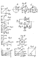
- FIG. 19 shows a phase jump on the principle of quadrature amplitude modulation.
- the basic alternating currents u (sin) and V (cos), the have the same frequency, are 90 degrees out of phase with each other.
- the total alternating current is designated us. For example, if the alternating current v is switched off at us at zero crossing 0, a phase jump occurs. The total alternating current us then becomes the same as the basic alternating current u, that is to say in phase and amplitude. If the basic alternating current v (Ov) is switched off again at the zero crossing, a phase jump is generated again.
- the period also changes as a result, namely that when v is switched off, the period T / 2ab and when v is switched on, the period T / 2 becomes.
- the amplitude of the total alternating current us also decreases by the amount AU, and increases again by the amount when v is connected.
- phase change is based on the principle of quadrature amplitude modulation, in which the amplitudes in the circuits of the basic alternating currents are changed by changing the resistance, or there may also be amplifications.
- the total alternating current gets a phase shift with every change. This is explained using the principle of vector representation.
- Usin and Ucos are two alternating currents of the same frequency offset by 90 degrees with the amplitudes u and v.
- the total alternating current or Vector is then US. Since u and v are the same size, US is 45 degrees ahead of u.
- FIG. 1 the phase change is based on the principle of quadrature amplitude modulation, in which the amplitudes in the circuits of the basic alternating currents are changed by changing the resistance, or there may also be amplifications.
- the total alternating current gets a phase shift with every change. This is explained using the principle of vector representation.
- Ucos are two alternating currents of the same frequency offset by 90 degrees with the ampli
- the vectors u and v are selected such that a phase lead to u of 22.5 degrees is produced. If the vectors receive the quantities u1 and v1, a sum vector US2 arises which is 22.5 degrees behind the basic alternating current v1. A phase jump can also be carried out in several stages, which has a very favorable effect on the bandwidth. If the phase jump stages are generated with the aid of two sinusoidal alternating currents which are phase-shifted by 90 degrees by adding them, and their electrical values are changed, then amplitude changes can be avoided by simultaneously changing the vectors determining the phase angle accordingly. This is explained in more detail with reference to FIG. 3. If the vectors u and v were changed linearly in this, the sum amplitude would also change.
- the distance u / u1 is smaller than the distance u1 / u2.
- FIG. 1 The sum vectors US1 / US2 and US3 / US4 have approximately the same angle, but different amplitudes. With this arrangement, there are 4 characteristic states available. The angular states can of course also be extended to 180 and 360 degrees.
- One of the two superimposed alternating currents can also be provided as synchronizing alternating current. Such an example is shown in FIG.
- the alternating current has only 2 phases as characteristic states.
- the alternating current is provided with the vector u and a phase angle 0.
- the other characteristic state is formed by the phase angle x.
- the phase angle is set in stages - you can also do this continuously - using the same stages v1, v2, v3 and v4.
- the amplitude, ie the sum vector US also changes as a function of the angle x. If you want to prevent this, the vectors u and v must be changed with non-linear steps u1,2,3 - v1,2,3, as shown in Fig.6. The sum vectors are then always of the same size.
- FIG. 8 A basic circuit for the vector diagram of FIG. 8 is shown in FIG. As can be seen from FIG. 8, there are only 2 characteristic states, namely the vector u and the angle x.
- the vector v is 90 degrees out of phase only for setting the angle x. 7
- the coding alternating current is generated in the oscillator Osc. Once it goes through a phase shifter of 90 degrees, the resistor Wi1 and the addition stage Ad on the transmission path.
- the other circuit goes via Wi2, via the electronic switch eS and, when the switch is closed, also via the addition stage, to be precise overlaid with the alternating current, shifted 90 degrees, on the transmission path.
- the amplitudes of the two alternating currents u + v are of the same size.
- the switch is controlled as follows.
- the coding alternating current is 90 degrees out of phase, or the total alternating current US is branched off to a limiter B after the addition stage Ad.
- the limiter then outputs synchronization pulses Js, which are fed to an encoder Cod.
- the code is also switched on to the encoder, for example a binary code in which 10 periods represent one step.
- Characteristic state 1 is, for example, phase position u FIG. 8 and characteristic state 0 is phase position US. This synchronization ensures that the vector change always occurs only at the zero crossing, ie this vector v always takes on the value v and zero in the example.
- There is also a counter in the encoder that counts the periods. Is the characteristic state There are 2 times 1, so switching takes place after 20 periods, etc.
- the evaluation on the receiving side can be carried out in a known manner using a reference phase or, since there is also differential phase modulation, using a frequency discriminator or a phase discriminator. Another method is used in this example. This will be explained with reference to FIG. 9.
- 9a shows the vectors of the two characteristic states v and US.
- a half wave of the characteristic state US is shown in FIG. 9b. If the switch eS in Fig. 7 is opened, the vector u becomes zero, so that there is a phase jump from US to v. This means a phase lead of 45 degrees. This shortens the next half-wave v, which is shown in broken lines.
- the pulse generated in the limiter becomes shorter (T / 2Spv).
- the phase shift from v to US is shown in FIG. 9c.
- the alternating current is lagging by 45 degrees.
- the period T / 2 increases (T / 2SpUS), the pulse at the limiter also increases. In the case of a binary code, it is sufficient if a phase jump is registered. With the limiter in Fig. 7, the negative pulses always remain the same, because in the example the phase change takes place at the half-wave 0 to 180 degrees. So you only need to lock the counter during the same impulses of the negative half-waves and release them during the positive half-waves.
- the difference phase modulation can also be carried out. 10, for example, a phase difference of 45 degrees is always arranged in a leading manner.
- FIG. 11 shows a phase modulation in which the phase change takes place in stages. This has the advantage that the frequency hardly changes during the phase jump, that is to say that harmonics hardly arise during the change.
- a plurality or a plurality of sine and cosine alternating circuits are provided, with in the respective circuits of a plurality or a multiplicity of means with which such a change in the electrical conditions of these circuits is brought about that the predetermined phase change takes place .
- an encoder is provided which takes effect as a function of the code.
- a tap of the total alternating current is also provided for the phase-correct control, with means for switching on and off at the zero crossing.
- Such a gradual change can e.g. according to the vector diagrams of FIGS. 2, 3, 4, 5 or 6.
- the coding alternating current is generated again in the oscillator Osc and is switched directly to the switch arrangement ES and once via a phase shifter of 90 degrees. Resistors are switched into the circuits of the two alternating currents, which are 90 degrees out of phase with one another, with the aid of electronic switches eS1 to esn and es11 to es11n. The size of the vectors u and v of FIGS. 2, 3, 4, 5 and 6 is determined with these resistors. The two alternating currents are then superimposed in the adder and connected to the transmission path. The electronic switches are controlled from the encoder.
- the respective code "Code” is connected to the encoder.
- the synchronization is carried out by pulses Js, which are generated in the limiter B with the aid of the total alternating current.
- pulses Js which are generated in the limiter B with the aid of the total alternating current.
- the resistors Wi1 to Win and Wi11 to Wi11n you can set the phase angle and also the amplitude values of the respective total alternating current.
- the phase and possibly also the amplitude are always changed at the zero crossing of the total alternating current.
- the data coded by phase modulation can be evaluated in a known manner using a reference phase, or if it is based on the principle of differential phase modulation, by comparing the phase of two successive states, the first state being stored, or using a frequency discriminator, coincidence demodulator or other phase comparator be performed.
- a new evaluation principle is used, as already briefly explained in the description of FIG. 9. With this principle, as a measure of the phase position. Phase change the half or Period as absolute or Reference value taken. The evaluation is done in such a way that with the help of a measurement or Counter, which with a compared to the smallest occurring coding frequency of the half or Periods multiple frequency is controlled.
- the measuring pulses are started at the beginning of the respective half or Period to the measurement or Counter switched on and switched off again at the end of the same.
- the output reached at the end of the measurement or Counter is then a measure of the relative bezw. absolute phase position. This is explained in more detail with reference to FIGS. 12, 13, 14 and 15.
- the alternating current coming from the transmission path in Fig. 12 becomes if required via an amplifier V, a limiter B supplied. In the limiter, the alternating current periods are converted into pulses hs / 1s, as can be seen from FIG. 13.
- the encoding alternating current is shown in FIG. 13a.
- T / 2SpUS i.e.
- the zero line in the case of a lagging phase shift, as shown in FIG. 9c, the zero line can be shifted somewhat to the minus side, as shown in dashed lines in FIG. This always results in the same IS impulses.
- the measuring pulses Jm have 10 times the frequency, so that an hs-related or Is pulse 10 Jm pulses fall. If the zero line lowering is carried out, this may also have to be taken into account for the measuring pulses.
- 15 is a circuit arrangement for decoding phase positions. Phase jumps shown. This is done with the help of a counter Z, which with a multiple number of outputs relative to the frequency of the coding half-periods. Periods.
- a generator of measuring pulses and means for processing the information for the control is provided.
- a gate arrangement ensures that only during the half or Period control of the counter takes place.
- means are arranged in the outputs of the counter, the position of the counter after the end of the half-bezw. Mark the period.
- the phase jumps are between 0 and 90 ° and 90 ° and 0 °.
- FIG. 14 there is therefore once the distance between two IS pulses Phn with a lagging phase shift and Phv with a leading phase shift.
- the measuring pulses Jm are present at the gate G1 and the pulses ls at the other input. IS pulses block the gate.
- the gate G1 is active, at the output there are 1 pulses, which are reversed to h pulses with the aid of the gate G2. These pulses are fed to the counter Z. If the distances between the ls pulses are equal, in Fig. 14 equal to Jn, the counter is always switched up to the output Jn. There is a gate G5 at this output, and there is also an is pulse at the gate such that h is present at the gate input when it is present. The gate output of G5 is routed to the reset of the counter, possibly with the interposition of a potential reversal gate.
- the counter is therefore switched back with the pulse ls. If the distance between the pulses is equal to Phn (Fig. 14), the counter Z is switched to the output Phn.
- the gate G6 is located at this output. At the other input of G6, the pulse ls is such that it is present h creates. Then at the output of gate G6 is l. With the help of gate G7, the potential is reversed to h. The output of gate G7 is fed to a bistable multivibrator B2. At the exit there is h. A "1" is marked with this potential. A monostable multivibrator M2 is also connected to this output. The output of this is due to the bistable flip-flop B1, which is now switched back if it is in the working position.
- the counter Z is also switched back via R. If the distance between the ls pulses is equal to Phv (FIG. 14), the counter is only switched up to the output Phv. According to the output Phn, G3, G4 and the bistable flip-flop B1 now come into effect. The potential h is now at the output of B1, which corresponds to the binary characteristic state 0. The bistable flip-flop B2 is brought back to the starting position via the monostable flip-flop M1, and the counter is reset via R. In this way, for example, binary coding can be transmitted and evaluated. You may also be able to switch the Phv, In and Phn outputs to 2 or more counting outputs if tolerances are allowed for the distances between the IS pulses. If the phase change is gradual (Fig.
- the phase change is distributed over the number of stages or on the number of periods included in the continuous process. If the phase change is divided into, for example, 10 steps, each step being assigned a period of the alternating current and if the phase change is 90 degrees, there is a phase step change of 9 degrees for each period.
- FIG. 17a shows 10 periods without phase change and in FIG. 17b 10 periods each with 9 degrees, that is, 90 degrees phase change. It can be seen from FIG. 17b that a phase change of 18 degrees already exists after 2 periods and that of 90 degrees after 10 periods. Without a reference phase, it must first be determined with which period the 90 degree phase shift has been achieved.
- This invention can be used, for example, in AC telegraphy (frequency division multiplexing). For example, if a frequency of 3000 Hz is assigned to a channel and a step number with 20 periods for one step, 150 steps per second are possible. Because of the gradual phase change only a very narrow band is required. Of course, you can also combine a phase shift with amplitude levels.
- This method can also be used with the 4 PSK, 4 QAM, 8 PSK, 16 PSK and 16 QAM.
- This method can also be used for digital as well as analog voice transmission, for example according to the pulse code modulation system and pulse amplitude modulation system (patent DE 30 10938), patent application DE P 33 40 377.5), as well as for remote control.
- phase jump can be subdivided into several or a plurality of phase stages, whereby these can assume leading and lagging values.
- the phase jump itself is assigned a predetermined leading or lagging phase jump. If necessary, an amplitude or apparent amplitude coding can also be provided.
- the "O" is preceded with a phase shift of 50 periods and the "1" is coded with one with a 50 period, it is possible, for example, to provide phase shifts of different sizes during the respective 50 periods, the total phase shift always being the same.
- phase jumps During the periodic step-by-step phase jumps, the period is smaller or larger, that means that the frequency also changes.
- One can code such phase jumps by switching to a different frequency and by the number of periods. It only has to be guaranteed that a switchover to another frequency takes place at the zero crossing. For example, at a frequency f1 and the other of f1 / 2 there is always a common zero crossing after a period of f1 / 2. The phase jump would then always be 360 degrees. In this way, any phase jump can be generated.
- the transition from one frequency to the other can also be made continuously. Frequency modulation can be provided for this purpose. 22 shows a transition from one frequency to another with the aid of rectangular pulses, that is to say from one period to another.
- phase position is then a measure of the phase shift or. Phase position, as also shown in FIG. 24.
- the binary pulses J1, J2, etc. are fed to a frequency modulator FM. With a small frequency deviation, the bandwidth is practically twice the modulation frequency. If you want a frequency transition from one frequency to the other similar to the soft keying in telegraphy, the input signals must be designed, for example, according to FIG. 23, step 3.4. Flattening can be achieved with just one capacitor.
- An ongoing frequency change can only be evaluated with the help of a summation of phase jumps. Every change in frequency means a phase jump compared to a center frequency. For a step or Impulse must then be provided for so many periods that there is a measurable phase jump in the summation. For example, good is sufficient a sum phase jump of 60 degrees if you make a period comparison. At 60 degrees the cos is 0.5, so that a shortening e.g. to 3/4 of the half-period (Fig.9b).
- the incoming coding alternating current is, as shown in FIG. 12, possibly fed to a limiter B via an amplifier V. This is converted into impulses Jm.
- the positive impulses are denoted by hs and the negative ones by ls.
- FIG. 18a, b show a step-wise phase change on the basis of vectors.
- the vector u is to be shifted in phase by the angle a.
- an alternating current of the same frequency is added to the vector v, which is phase-shifted 90 degrees ahead of u.
- the vector u must therefore be reduced by the amount ud to u1.
- a further phase shift leading by the same amount is to take place. If the sum vector sul is to be equal to that of su, then both the vector u1 by ud to u2 and the level V 'by vd to v1 must be reduced.
- the characteristic states can be evaluated by simply dimensioning a half-period.
- the pulses required for the comparison can be generated with a limiter circuit according to FIG. 12 (B) or with a Schmitt trigger. You can also count the number of periods. E.g. If the period is selected in a ratio of 2: 3, you can switch to the lower frequency after 3 periods. If you choose the higher frequency with 2400 Hz, the lower frequency is 1600 Hz. In this way you could code 800 bit / s. The switchover always takes place at zero. Such arrangements are also suitable for single-channel data transmission systems. If filters are still provided for the individual frequencies, e.g. a frequency between 2400 Hz and 1600 Hz.
- pulse modulation Methods are already known in which, during pulse modulation, the pulses are caused by sine half-waves. Periods which are transmitted in an uninterrupted sequence of positive and negative half-waves and in which the characteristic states are coded by the size of the amplitudes.
- pulse amplitude modulation published application DE 33 40 377 A1
- sampling pulses are determined by the size of the half-wave or.
- Period amplitudes of an alternating current of a frequency are coded analogously.
- 29 and 30 show frequency-modulated oscillations in which the information is encoded by the amplitudes of half-waves of an alternating current of a frequency.
- the respective amplitude values of the half-waves of the signal voltage are marked by a largest or smallest absolute phase value of the frequency-modulated half-waves belonging to a signal half-wave.
- Fig. 28 the principle of an FM radio transmitter is shown.
- the LF signal is fed to an analog / single-frequency AC converter AE.
- this coding alternating current is then fed to a frequency modulator FM with an oscillator Osc.
- the modulated carrier of the output stage E and the antenna is then fed via amplifier stages V.
- M1 is a comparison amplitude.
- M2 is twice the comparison amplitude and M3 is twice the comparison amplitude at double frequency.
- FM1, FM2 and FM3 are the associated frequency-modulated vibrations. If one compares the shortest half-periods T / 2TrFM for the different modulation oscillations M1, M2, M3, one sees that in each case there is almost a halving of the period, i.e. that when using only one frequency for coding speech resp. Data the frequency band becomes much smaller.
- Such coding according to patent DE 30 10 938 can also be used with existing radio devices, for example in FIG. 28.
- One can use the digital coding frequency Make it even smaller if, instead of 2 levels, more levels, e.g. 3, are provided, as shown in Fig. 29a.
- the half-period durations of the frequency-modulated negative half-waves TrM / 2 at the 3 different amplitude sizes 1, 2, 3, as shown in FIGS. 29c, d, e can be measured well.
- the frequency modulator can also be controlled with direct current analog or digital.
- 27 shows a circuit for a digital control.
- the frequency is always the same.
- the code is given by the amplitude of the rectangular pulses.
- the DC pulses are sensed by the electronic switches es1-es4.
- the encoder Cod controls the electronic switches.
- the code and then the synchronization pulses Js, which are generated in the limiter, are applied to the encoder Cod.
- the limiter receives an AC branch current from the frequency modulator. The zero crossing of the AC branch current is always marked with the synchronization pulses.
- the frequency modulator FM is connected to the amplitude modulator M, to which the oscillator alternating current Osc is also conducted.
- the modulated carrier is then guided to the transmitting antenna via amplifier stages V and the final stage E. To compensate for the interference and harmonic voltages, this can be fed back via a filter Fi, which blocks the useful signals, and a phase rotator Ph of 180 degrees via a branch path of the output stage.
- 26 and 25 show once a 2-stage and once a 3-stage rectangular pulse code of a frequency.
- a coding is described below in which, in order to distinguish two information channels in the receiving station, the code elements of both channels are given such a different amplitude size that an evaluable frequency spacing is achieved in the case of frequency-modulated transmission. This is shown in FIGS. 31 and 32.
- a coding of 2 channels is shown in these, one with rectangular and one with half-wave pulses. Only two characteristic states are available, u1 and u2. The smallest amplitude of channels II and W2 is twice as large as the largest amplitude of channels I and W1. Only one frequency is used for the coding, no phase equality is necessary. Since the amplitudes of different sizes generate different frequencies in the frequency modulator (Fig. 30), you can use both channels - you can too be several - send via one transmission path.
- an electronic switch eS is used to switch from a channel with the smaller amplitude coding to the one with the larger amplitude coding. If the encodings in FIG. 31 are offset from one another by 180 degrees, the switchover takes place at the zero crossing.
- the codings are in phase, so that an alternating current is then connected to the frequency modulator FM in an uninterrupted sequence of positive and negative half-waves.
- the channels must be coded using periods so that one half-wave from W1 and the next half-wave from W2 are alternately connected to the frequency modulator.
- two frequency modulators FM1 and FM2 are provided for the transmission, which transmit the respective AC band to the transmission path via a decoupler E.
- the oscillator is common to all channels.
- two identical frequency modulators FM1I and FM1II are provided for the transmission of the two channels. Since, as can be seen from FIG. 29, the large amplitudes occupy a large frequency range, it is necessary to filter out the frequency range of the small amplitudes with the filter Fi.
- the two frequency bands are then combined and transmitted via an adder Ad.
- 16 shows a circuit for the generation of small and large amplitudes of alternating current half-waves. Periods or rectangular pulses and their phase-in connection, for example at 180 and 0/360 degrees.
- the alternating coding current is generated in generator G.
- Two circuits with resistors R1 and R2 are provided for the large and small amplitudes.
- the electronic switch eS is controlled by a coder Cod, which is provided with the code and a limiter - it can also be a Schmitt trigger - to which the coding alternating current is also supplied, the synchronization pulses which are obtained from the coding alternating current are switched on.
- the synchronization pulses ensure that the electronic switch is always operated at the zero crossing.
- Fig. 28 the principle of use in a transmitter for radio transmission with frequency pre-modulation is shown.
- the carrier frequency is generated in the oscillator Osc / G and fed to the frequency modulator FM.
- the language Sp is to be frequency modulated in FM.
- an analog / single-frequency AC converter A / E is inserted between the speech signal and frequency modulator FM. That means the speech is transcoded into an alternating current of a frequency analog or digital. Only the amplitudes of this alternating current contain the information.
- the band of frequency-modulated oscillation becomes much narrower as a result.
- the frequency-modulated signal is then fed via the amplifier V to the output stage E of the transmitting antenna S.
- the single-frequency alternating current is then again obtained on the receiving side with the aid of the known methods (for example edge discriminator, ratio discriminator).
- the voice signal is then restored in a single-frequency AC / analog converter I / O.
- Patent DE 30 10 938 discloses a method for digital information coding in which binary code elements are formed from the half-waves or periods which are transmitted in an immediate succession of positive and negative half-waves.
- the two characteristic states 1.0 are encoded by a large amplitude value and a small amplitude value.
- the period is provided as a code element.
- Interval coding requires 8 bits for digital voice transmission.
- the code element can also be multi-level, e.g. shown in Figure 4, with leading and lagging phase shift.
- a principle of analog / single frequency AC conversion is disclosed in European patent application 0110427.
- the values of the sampling are analogously corresponding to the pulse amplitude modulation PAM by the amplitudes of the half-waves. Coded periods of only one alternating current. This sampling alternating current is assigned half the sampling frequency when using half-waves and the sampling frequency when using periods. The interval values are coded analogously by the size of the amplitudes.
- FIGS. 37a, b, c A method is disclosed in German Offenlegungsschrift No. 3223312 in which the luminance signal, ie the brightness of the pixels, is caused by the half-waves. Periods of only one alternating current can be coded. This principle is explained with FIGS. 37a, b, c.
- Fig. 37a that is Luminance signal shown, with a white value (10), a black value (75) with intermediate values and line pulses (100).
- BE is the pixel.
- VBE is the brightness voltage.
- the pixel voltages are modulated onto a carrier fT in FIG. 37b, specifically by means of amplitude modulation.
- the modulation frequency fM can range from direct current to 5 MHz.
- fMB is half the sampling time of the pixels.
- the half-waves of the coding alternating current are provided for coding the pixels.
- a half wave corresponds to the pixel BE.
- the amplitude UBE of the respective half-wave corresponds to the respective pixel voltage VBE of FIG. 37a.
- 37c shows that the luminance signal can be transmitted in a very narrow-band, frequency-modulated manner.
- the digitized sound can be brought into the 11.5us, for example, if the color signals are coded differently, i.e. if the burst is no longer required is (eg German patent application P 32 29 888), or you can also use the black shoulder for digital audio coding.
- the basic color signals red and blue can also be transmitted serially (DE P 3229888).
- FBAS color picture blanking synchronizing signal
- This transmission method can also be used in time-division multiplexing, namely analog and digital.
- the basic circuit for an analog time-multiplexed transmission of speech is shown in Fig. 36.
- Fig.36a 4 voice channels are combined in a time-multiplexed manner. Since the sampling frequency is 8 KHz, a tap frequency of 32 KHz is required for the 4 channels.
- a single-frequency alternating current of 32 kHz is then required for the coding, if the periods are provided as code elements.
- the samples are then transferred to the amplitudes of the periods in an analog / single-frequency AC converter A / E.
- the phase coding according to the invention can also be used for multi-value coding and for the encryption of messages. So you can e.g. 5, 10, 15 and 20 phase stages in the form of periods, the change in the direction of the phase shift in each case marking the respective group of periods. In addition, you can use an amplitude coding. If you want to encrypt a message, you can e.g. Provide 50 periods that add up to a predetermined phase jump. A leading phase shift means e.g. the binary value "1" and one lagging the binary value "0". If there is no phase shift compared to the previous value, the 50 periods have the same binary value as the previous 50 periods.
- amplitude steps and phase jumps can be provided within the respective 50 periods, which can take any direction and size, but the predetermined overall phase jump does not change. So you can not only change the 5, 10, 15 etc. phase levels in the form of period durations evenly, but also provide different phase groups within the groups in the form of period durations of different sizes.
- the respective overall phase jump can therefore be formed from 2 or a plurality of identical or unequal leading and / or lagging individual phase jump stages.
- levels can be assigned to the code element, e.g. B. the number of periods, a leading, lagging phase shift or no change in phase, 2 or more amplitude levels.
- the attenuators Wi1, .. Wi11 in the two AC circuits of FIG. 11 can also be connected in series and the electrical change can be brought about by a short circuit in a predetermined sequence.
- the evaluation based on the principle of dimensioning the half or Periods can not only be based on the principle of coding on the basis of the addition of two alternating currents of the same frequency that are phase-shifted by 90 degrees by changing the electrical conditions, but also in other methods such as phase modulation as frequency modulation with frequency-dependent modulation voltage or in the generation by downstream phase shifters.
- the principle of coding with the phase according to the present invention can also be used in pulse phase modulation multiplex operation, both in the phase shift and in the sum phase shift method.
- One or more periods of the coding alternating current are then serially assigned to a channel and phase-shifted analog or digitally in accordance with the associated quantization interval.
- U.U. it is necessary to temporarily store the values of the quantization intervals, possibly also at the evaluation point.
- a special synchronization channel is not required.
- the synchronization can e.g. by increasing the amplitude of a period which is currently in the normal position.
- a coding alternating current is shown in FIG. Since the duration of the half-period Period can be of different sizes (Fig. 21, 0.01, 02.03), each zero crossing must be determined during the transmission according to the principle of Fig. 33 and then a switchover to the half-period or period of the corresponding channel must take place. the respective value must then be buffered before phase coding. With analog amplitude coding you can 2 or more amplitudes of half-waves. Take periods. The total amplitude can then be obtained by summation.
Description
Die vorliegende Erfindung befasst sich mit einem Verfahren zur Erzeugung eines Sendesignals zur Verwendung insbesondere bei der Phasensprungtastung, bei der Pulsphasen-Pulsdauer-Pulsfrequenz- und Winkelmodulation.The present invention relates to a method for generating a transmission signal for use in particular in phase jump sampling, in pulse phase, pulse duration, pulse frequency and angle modulation.
Ein Hauptgebot bei der Übertragung von Information ist neben der Wirtschaftlichkeit die Sicherheit. Ein Mittel um dies zu erreichen ist der Code und das Übertragungsverfahren. Die Wirtschaftlichkeit hängt dabei hauptsächlich von der erforderlichen Bandbreite ab. So wurden zur besseren Ausnutzung der Übertragungswege mehrwertige Codierungen und zur sicheren Übertragung z.B. Phasen-Frequenz- und die Pulsmodulation verwendet. Die mehrwertigen Modulationsarten waren aus Gründen der Übertragungssicherheit und der Wirtschaftlichkeit nur bis zur 16-wertigen Phasenmodulation PSK (Phase Shift Keying) bezw. bis zur 16-wertigen Quadratur-Amplituden-Modulation QAM brauchbar. Aber auch bei diesen Codierungen waren erhebliche Bandbreiten und ein erheblicher Aufwand erforderlich.In addition to cost-effectiveness, a key requirement when transmitting information is security. One way to do this is through the code and the transmission method. The economy mainly depends on the bandwidth required. For better utilization of the transmission paths, multi-valued coding and for secure transmission, e.g. Phase-frequency and pulse modulation are used. For reasons of transmission security and economy, the multi-value modulation types were only up to the 16-value phase modulation PSK (phase shift keying). up to the 16-valued quadrature amplitude modulation QAM can be used. But even with these encodings, considerable bandwidths and considerable effort were required.
Diesbezüglich ist auch ein Verfahren zur Nachrichtenübertragung mittels Winkelmodulation bekannt, bei welchem die Phasenänderung bei der Modulation derart erfolgt, dass im Codierwechselstrom Phasensprünge vorbestimmter Grösse entstehen. Da sich bei jedem Phasensprung auch die Frequenz ändert ist für die Übertragung eine erhebliche Bandbreite erforderlich.In this regard, a method for transmitting messages by means of angle modulation is also known, in which the phase change in the modulation takes place in such a way that phase jumps of a predetermined size occur in the coding alternating current. Since the frequency changes with each phase jump, a considerable bandwidth is required for the transmission.
Weiterhin ist eine Pulsamplitudenmodulation PAM bekannt, bei der die Grösse der Amplituden von Halbwellen bezw. Perioden eines Wechselstromes als Kennzustände für die Grösse der PAM Pulse vorgesehen werden. Zur Frequenzreduzierung werden dabei die PAM-Pulse zeitmultiplex auf die Halbwellen bezw. Perioden von um 90° phasenverschobener Codierwechselströme übertragen. Bei dieser Art der Codierung kann nur die Grösse der Amplitude als Kennzustand verwendet werden, sodass nur eine kleine Stufenzahl möglich ist.Furthermore, a pulse amplitude modulation PAM is known, in which the magnitude of the amplitudes of half-waves or. Periods of an alternating current can be provided as characteristic states for the size of the PAM pulses. To reduce the frequency, the PAM pulses are time-multiplexed onto the half-waves. Transmit periods of 90 ° out-of-phase coding alternating currents. With this type of coding, only the size of the amplitude can be used as a characteristic state, so that only a small number of stages is possible.
Weiterhin ist eine Schaltungsanordnung bekannt, bei der die Grösse von Amplitudenstufen für ein Winkelmodulationsverfahren durch eine den Stufen entsprechende Zahl von parallen Wechselstromkreise mit entsprechenden Dämpfungen bezw. Verstärkungen eingestellt werden kann. Dabei sind Mittel vor gesehen, die eine An-,Aus- oder Umschaltung der Dämpfungen bezw. Verstärkungen je nach vorbestimmter Stufe vornehmen. Auch bei diesem Schaltungsprinzip entstehen Phasensprünge die ein breites Frequenzband benötigen.Furthermore, a circuit arrangement is known in which the size of the amplitude stages for an angle modulation method by means of a number of parallel AC circuits with corresponding damping. Reinforcements can be adjusted. Here, means are seen before, the on or off or switching of the damping. Make reinforcements depending on the predetermined level. This circuit principle also results in phase jumps that require a broad frequency band.
Aufgabe der vorliegenden Erfindung ist es nun eine Codierung zu schaffen, die in Verbindung mit bekannten Übertragungsverfahren, die bei der Übertragung eine wesentlich geringere Bandbreite bei gleicher oder noch grösserer Sicherheit als bei den bekannten Verfahren benötigen. Dies wird dadurch erreicht, indem der jeweilige Phasensprung durch mehrere oder eine Vielzahl von Phasensprungstufen gebildet wird. Die Phasensprungstufen werden dabei so erzeugt und so aneinandergereibt, dass eine ununterbrochene Folge entsteht. Als Mass für die Phasenlage wird dabei die positive oder negative Differenz der Summe der Halbperioden- bezw. Periodendauern zu den entsprechenden Bezugsphasen bezw. Bezugshalbperioden bezw. Periodendauern oder der Unterschied der Phasenlage, al so der Halb- bezw. Periodendauern zur Periodendauer des vorhergehenden Phasensprunges, oder bei einer Frequenzmodulation, der grösste und/oder kleinste Absolutphasenwert der zu einer Signalhalbwelle gehörenden frequenzmodulierten Halbwellen hergenommen. Vorzugsweise werden dabei als Codeelemente sinusähnliche Halbwellen bezw. Perioden oder Rechteckimpulse vorgesehen. Die Auswertung erfolgt dabei mit Hilfe eines Mess- bezw. Zählgliedes, das mit einergegenüber der kleinsten vorkommenden Codierfrequenz der Halbperioden bezw. Perioden vielfachen Frequenz gesteuert wird. Die Messimpulse werden dabei mit dem Beginn der jeweiligen Halbperiode bezw. Periode an das Mess- bezw. Zählglied angeschaltet und am Ende derselben wieder abgeschaltet. Der dabei erreichte Ausgang am Mess- bezw. Zählglied ist dann ein Mass für die relative bezw. absolute Phasenlage.The object of the present invention is to provide a coding which, in connection with known transmission methods, which require a substantially smaller bandwidth during transmission with the same or even greater security than with the known methods. This is achieved in that the respective phase jump is formed by several or a plurality of phase jump stages. The phase jump stages are generated and rubbed together in such a way that an uninterrupted sequence arises. The measure for the phase position is the positive or negative difference between the sum of the half-periods. Periods for the corresponding reference phases or Reference half-periods Periods or the difference in phase, al so the half or Periods to the period of the previous phase jump, or in the case of frequency modulation, the largest and / or smallest absolute phase value of the frequency-modulated half-waves belonging to a signal half-wave. Sinusoidal half waves are preferably used as code elements. Periods or rectangular pulses are provided. The evaluation is carried out with the help of a measurement or Counter, which with a compared to the smallest occurring coding frequency of the half periods. Periods multiple frequency is controlled. The measuring impulses are started at the beginning of the respective half-period. Period to the measurement or Counter switched on and switched off again at the end of the same. The output reached at the measurement or Counter is then a measure of the relative bezw. absolute phase position.
Mit diesem Verfahren ist es nicht möglich im Funkbereich wieder mehr Bandbreite freizubekommen, sondern auch, da es bei allen Arten der Informationsübertragung einsetzbar ist, beim Kabel und bei der Glasfaser. Auch die auf dem Prinzip der Erfindung konzipierten digitalen Verfahren können über vorhandene Trägerfrequenzsysteme übertragen werden. In Fig. 20 ist z.B. das Prinzip einer bisher verwendeten vierwertigen Phasenmodulation dargestellt, bei der mit Hilfe zweier um 90 Grad gegeneinander versetzter Wechselströme gleicher Frequenz U und V, durch Addition derselben die Phasensprünge im Summenwechselstrom SU erzeugt werden. Aus dem Summenwechselstrom , der der Träger des Codes ist, ist ersichtlich, dass dieser keinen gleichförmigen Wechselstrom mehr darstellt. Es entsteht dadurch wie auch aus der Fourier-Analyse bekannt ist, ein sehr breites Frequenzband. Bei der vorliegenden Erfindung hingegen werden im Höchstfall Phasensprünge bis 90 Grad so angeordnet, dass der Codewechselstrom aus einer ununterbrochenen Folge von positiven und negativen Halbwellen besteht. Die Veränderung der Vektoren der Grundwechselströme sin/cos erfolgt dabei insbesondere beim Nulldurchgang des Summen- oder eines der Grundwechselströme. Ein weiteres Merkmal der Erfindung ist, dass der Gesamtphasensprung aus zwei oder mehreren Einzelphasensprüngen zusammengesetzt wird, sodass die jeweilige Frequenzänderung sich in sehr engen Grenzen bewegt, sodass bei phasen- oder frequenzmodulierter Übertragung ein wesentlich schmaleres Band als bei den herkömlichen Verfahren erforderlich ist, entsteht, besonders dann, wenn das nachfolgend angeführte Merkmal zusätzlich angewendet wird. Wird bei einer Phasenänderung jeweils nur ein Vektor der Grundwechselströme geändert, so hat dies zur Folge, dass auch eine Amplitudenänderung beim Summenwechselstrom entsteht. Eine solche Änderung kann dadurch vermieden werden, indem gleichzeitig beide Vektoren der Grundwechselströme so geändert werden, dass immer dieselbe Amplitude beim Summenwechselstrom entsteht. Ein weiteres Merkmal der Erfindung ist, die Codierung nur mit einem Wechselstrom bezw. sehr schmalbandig vorzunehmen und auf der Basis der Frequenzmodulation zu übertragen. Es ist ja bekannt, dass bei der Frequenzmodulation sowohl die Amplitude als auch die Frequenz in die Bandbreite mit eingehen. Eine schmalbandige Frequenzmodulation ist einer Amplitudenmodulation weit überlegen. Nachstehend wird nun die Erfindung an Hand der Zeichnungen näher erläutert. In diesen sind dargestellt:
- Fig.1: Vektoren der Grund- und des Summenwechselstromes.
- Fig.2: Vektoren des Summenwechselstromes bei wechselseitiger Änderung der Grundwechselströme.
- Fig.3: Stufenweise Phasenänderung mit Darstellung der Amplitudenkorrektur
- Fig.4: Eine Phasen- Amplitudencodierung.
- Fig.5 und 6: Ein mehrstufiger Phasensprung ohne und mit Amplitudenkorrektur.
- Fig. 8 und 9: Darstellung eines Phasensprunges und die Veränderung der Periodendauer.
- Fig.7: Prinzip einer Phasenänderung beim Nulldurchgang des Summenwechselstromes.
- Fig.10: Eine Differenzphasenänderung von 45 Grad.
- Fig.11: Eine stufenweise Phasenänderung.
- Fig.12: Auswertung eines über einen Übertragungsweg kommenden phasenmodulierten Wechselstromes.
- Fig.13 und 14: Auswertung der Periodendauer.
- Fig.15: Schaltung für die Auswertung der Periodendauer.
- Fig.16: Schaltung für die Erzeugung eines Wechselstrombinärcodes.
- Fig.17: Prinzip der stufenweisen Phasensprünge.
- Fig. 18: Vektorelle Darstellung der Amplitudenkonstanthaltung bei der Phasencodierung.
- Fig.19: Darstellung eines Phasensprunges an Hand der Grund- und Summenschwingung.
- Fig.20: Eine vierwertige Phasencodierung herkömlicher Art.
- Fig.21: Eine Phasen-Amplitudencodierung.
- Fig.22 und 23: Pulsformen für die Frequenzmodulation.
- Fig.24: Darstellung der Phasenverschiebung bei Rechteckpulsen.
- Fig.25,26 und 27: Prinzip der Funkübertragung von Rechteckpulsen und Darstellung von Codeelementen.
- Fig.28: Blockschaltbild für die frequenzmodulierte Funkübertragung eines pulsamplitutenmodulierten Sprachsignals.
- Fig.29: Frequenzänderung durch Amplitudenänderung bei der Frequenzmodulation.
- Fig. 30: Frequenzänderung bei der Frequenzmodulation bei Änderung der Amplitude und der Frequenz der Modulationsfrequenz.
- Fig. 31,32,33,34 und 35: Wechselweise und frequenzmultiplexe Übertragung von 2 Kanälen auf der Basis der Frequenzmodulation über einen Übertragungsweg.
- Fig.36: Zeitmultiplexe Übertragung von Sprachkanälen auf Frequenzmodulationsbasis.
- Fig.37: Codierung des Luminanzsignals nur mit einem Wechselstrom einer Frequenz.
- Fig . 1 : Vectors of the basic and the total alternating current .
- Fig . 2 : Vectors of the total alternating current when there is a mutual change in the basic alternating currents.
- Fig . 3 : Gradual phase change with representation of the amplitude correction
- Fig . 4 : A phase-amplitude coding.
- Fig. 5 and 6 : A multi-stage phase jump without and with amplitude correction .
- 8 and 9 : representation of a phase jump and the change in the period.
- Fig . 7 : Principle of a phase change at the zero crossing of the total alternating current .
- Fig . 10 : A difference phase change of 45 degrees.
- Fig.11 : A gradual phase change.
- Fig . 12 : Evaluation of a phase-modulated alternating current coming via a transmission path.
- Fig. 13 and 14 : Evaluation of the period.
- Fig . 15 : Circuit for evaluating the period.
- Fig . 16 : Circuit for generating an alternating current code .
- Fig . 17 : Principle of gradual phase jumps.
- Fig. 18 : Vector representation of the amplitude maintenance during phase coding.
- Fig . 19 : Representation of a phase jump on the basis of the fundamental and sum oscillation.
- Fig . 20 : A four-value phase coding of a conventional kind.
- Fig . 21 : A phase amplitude coding .
- Fig. 22 and 23: pulse shapes for frequency modulation.
- Fig. 24: Representation of the phase shift for rectangular pulses.
- Fig. 25, 26 and 27: Principle of radio transmission of rectangular pulses and representation of code elements.
- Fig. 28: Block diagram for the frequency-modulated radio transmission of a pulse-amplitude-modulated speech signal.
- Fig. 29: Frequency change due to amplitude change in frequency modulation.
- Fig. 30: Frequency change in frequency modulation when changing the amplitude and frequency of the modulation frequency.
- 31, 32, 33, 34 and 35: Alternate and frequency-multiplexed transmission of 2 channels on the basis of frequency modulation over a transmission path.
- Fig. 36: Time division multiplex transmission of voice channels on a frequency modulation basis.
- Fig. 37: Coding of the luminance signal only with an alternating current of a frequency.
In Fig.19 ist ein Phasensprung auf dem Prinzip der Quadraturamplitudenmodulation dargestellt. Die Grundwechselströme u (sin) und V (cos), die eine gleiche Frequenz aufweisen, sind gegeneinander um 90 Grad phasenverschoben. Der Summenwechselstrom ist mit us bezeichnet. Wird z.B. beim Null durchgang 0 von us der Wechselstrom v abgeschaltet, so entsteht ein Phasensprung. Der Summenwechselstrom us wird dann gleich wie der Grundwechselstrom u, also phasen- und amplitudengleich. Wird beim Nulldurchgang des Grundwechselstromes v (Ov) dieser wieder abgeschaltet, so wird wieder ein Phasensprung erzeugt. Wie aus dem Verlauf des us-Wechselstromes ersichtlich ist, ändert sich dadurch auch die Periodendauer und zwar wird bei der Abschaltung von v die Periodendauer T/2ab und bei der Zuschaltung von v die Periodendauer T/2zu. Auch die Amplitude des Summenwechselstromes us nimmt dabei um den Betrag AU ab, und bei der Zuschaltung von v um diesen Betrag wieder zu.FIG. 19 shows a phase jump on the principle of quadrature amplitude modulation. The basic alternating currents u (sin) and V (cos), the have the same frequency, are 90 degrees out of phase with each other. The total alternating current is designated us. For example, if the alternating current v is switched off at us at zero
Es gibt mehrere Methoden der Mehrphasenumtastung wie z.B. mittels verschiedener Netzwerke. Bei den nachfolgend aufgeführten Beispielen erfolgt die Phasenänderung auf dem Prinzip der Quadratur-Amplituden-Modulation, in dem in den Stromkreisen der Grundwechselströme die Amplituden durch Widerstandsveränderung, oder es können auch Verstärkungen sein, verändert werden. Der Summenwechselstrom bekommt bei jeder Veränderung eine Phasenverschiebung . Mit dem Prinzip der Vektorendarstellung wird dies erläutert. In der Fig.1 sind Usin und Ucos zwei um 90 Grad versetzte Wechselströme gleicher Frequenz mit den Amplituden u und v. Der Summenwechselstrom bezw. Vektor ist dann US. Da u und v gleiche Grösse haben ist US gegenüber u um 45 Grad voreilend. In der Fig.2 sind die Vektoren u und v so gewählt,dass eine Phasenvoreilung zu u von 22.5 Grad entsteht. Erhalten die Vektoren die Grössen u1 und v1, so entsteht ein Summenvektor US2, der zum Grundwechselstrom v1 22,5 Grad nacheilend ist. Einen Phasensprung kann man auch mehrstufig ausführen, was sich sehr günstig auf die Bandbreite auswirkt. Werden die Phasensprungstufen mit Hilfe zweier um 90 Grad phasenverschobener sinusförmiger Wechselströme durch Addition derselben erzeugt, wobei ihre elektrischen Werte verändert werden, so kann man Amplitudenänderungen in der Weise vermeiden, indem man die den Phasenwinkel bestimmenden Vektoren gleichzeitig entsprechend ändert. An Hand der Fig.3 wird dies näher erläutert. Würde man in dieser die Vektoren u und v linear verändern, so würde sich auch die Summenamplitude verändern. Will man dies vermeiden, so muss entsprechend der Zeichnung vorgegangen werden, also die Stufenänderung nicht linear durchzuführen. Der Abstand u/u1 ist kleiner als der Abstand u1/u2. Dasselbe gilt für v. Die Tatsache, dass mit einer stufenweissen Änderung der Vektoren sich auch der Summenvektor ändert, kann man dazu ausnützen, indem man zusätzlich eine Amplitudencodierung vornimmt. In Fig. 4 ist eine solche Anordnung dargestellt. Die Summenvektoren US1/US2 und US3/US4 haben ungefähr denselben Winkel, aber jeweils verschiedene Amplituden. Bei dieser Anordnung hat man also 4 Kennzustände zur Verfügung. Die Winkelzustände kann man natürlich auch auf 180 und 360 Grad ausdehnen. Man kann auch einen der beiden Überlagerungswechselströme gleich als Synchronisierwechselstrom vorsehen. In Fig. 5 wird ein solches Beispiel gezeigt. Der Wechselstrom hat nur 2 Phasen als Kennzustände. Einmal wird der Wechselstrom mit dem Vektor u und einem Phasenwinkel 0 vorgesehen. Der andere Kennzustand wird durch den Phasenwinkel x gebildet. Die Einstellung des Phasenwinkels erfolgt dabei stufenweise - man kann dies auch kontinuierlich machen - und zwar durch gleiche Stufen v1,v2,v3 und v4. Wie aus der Zeichnung ersichtlich ist, ändert sich dann auch die Amplitude, also der Summenvektor US in Abhängigkeit vom Winkel x. Will man das verhindern, so müssen die Vektoren u und v mit nicht linearen Stufen u1,2,3 - v1,2,3 verändert werden, wie in der Fig.6 gezeigt ist. Die Summenvektoren sind dann immer gleich gross.There are several methods of multi-phase shift keying, such as using different networks. In the examples listed below, the phase change is based on the principle of quadrature amplitude modulation, in which the amplitudes in the circuits of the basic alternating currents are changed by changing the resistance, or there may also be amplifications. The total alternating current gets a phase shift with every change. This is explained using the principle of vector representation. In FIG. 1, Usin and Ucos are two alternating currents of the same frequency offset by 90 degrees with the amplitudes u and v. The total alternating current or Vector is then US. Since u and v are the same size, US is 45 degrees ahead of u. In FIG. 2, the vectors u and v are selected such that a phase lead to u of 22.5 degrees is produced. If the vectors receive the quantities u1 and v1, a sum vector US2 arises which is 22.5 degrees behind the basic alternating current v1. A phase jump can also be carried out in several stages, which has a very favorable effect on the bandwidth. If the phase jump stages are generated with the aid of two sinusoidal alternating currents which are phase-shifted by 90 degrees by adding them, and their electrical values are changed, then amplitude changes can be avoided by simultaneously changing the vectors determining the phase angle accordingly. This is explained in more detail with reference to FIG. 3. If the vectors u and v were changed linearly in this, the sum amplitude would also change. If you want to avoid this, you have to proceed according to the drawing, i.e. not to carry out the step change linearly. The distance u / u1 is smaller than the distance u1 / u2. The same applies to v. The fact that with a step-by-step change in the vectors also the sum vector can be changed exploit by additionally performing an amplitude coding. Such an arrangement is shown in FIG. The sum vectors US1 / US2 and US3 / US4 have approximately the same angle, but different amplitudes. With this arrangement, there are 4 characteristic states available. The angular states can of course also be extended to 180 and 360 degrees. One of the two superimposed alternating currents can also be provided as synchronizing alternating current. Such an example is shown in FIG. The alternating current has only 2 phases as characteristic states. On the one hand, the alternating current is provided with the vector u and a
In Fig.7 ist eine Prinzipschaltung für das Vektordiagramm der Fig.8 dargestellt. Wie aus der Fig.8 ersichtlich ist, sind nur 2 Kennzustände vorhanden, und zwar der Vektor u und der Winkel x. Der Vektor v 90 Grad phasenverschoben ist nur für die Einstellung des Winkels x. In der Fig.7 wird im Oszillator Osc der Codierwechselstrom erzeugt. Einmal geht er über einen Phasenschieber von 90 Grad, den Widerstand Wi1 und die Additionsstufe Ad auf den Übertragungsweg. Der andere Stromkreis geht über Wi2 , über den elektronischen Schalter eS und wenn der Schalter geschlossen ist, ebenfalls über die Additionsstufe und zwar überlagert mit dem Wechselstrom 90 Grad verschoben, auf den Übertragungsweg. Gemäss der Fig.8 sind die Amplituden der beiden Wechselströme u+v gleich gross. Der Schalter wird folgendermassen gesteuert. Der Codierwechselstrom 90 Grad phasenverschoben, oder der Summenwechselstrom US wird nach der Additionsstufe Ad zu einem Begrenzer B abgezweigt. Der Begrenzer gibt dann Synchronisierimpulse Js ab, die einem Codierer Cod zugeführt werden. An den Codierer wird der Code ebenfalls angeschaltet, z.B. ein Binärcode bei dem 10 Perioden einen Schritt darstellen. Der Kennzustand 1 sei z.B. Phasenlage u Fig.8 und der Kennzustand 0 die Phasenlage US. Durch diese Synchronisierung wird erreicht,dass immer nur beim Nulldurchgang die Vektoränderung erfolgt, d.h. dieser Vektor v nimmt im Beispiel immer nur den Wert v und Null ein. Im Codierer ist noch ein Zählglied vorhanden, das die Perioden abzählt. Ist der Kennzustand 2 mal 1 vorhanden, so wird erst nach 20 Perioden umgeschaltet, usw. Die Auswertung auf der Empfangsseite kann in bekannterweise mittels Bezugsphase, oder da hier auch eine Differenzphasenmodulation vorliegt, mit einem Frequenzdiskriminator oder einem Phasendiskriminator erfolgen. Im vorliegenden Beispiel wird eine andere Methode verwendet. An Hand der Fig. 9 soll dies erläutert werden. In der Fig.9a sind die Vektoren der beiden Kennzustände v und US dargestellt. In der Fig.9b ist eine Halbwelle des Kennzustandes US dargestellt. Wird der Schalter eS in der Fig.7 geöffnet, so wird der Vektor u gleich Null, sodass ein Phasensprung von US nach v entsteht.Dies bedeutet eine Phasenvoreilung von 45 Grad. Dadurch wird die nächste Halbwelle v, die gestrichelt eingezeichnet ist, verkürzt. Der im Begrenzer entstehende Impuls wird kürzer (T/2Spv). In der Fig. 9c ist der Phasensprung von v nach US dargestellt.Der Wechselstrom wird um 45 Grad nacheilend. Die Periodendauer T/2 wird grösser (T/2SpUS), der Impuls am Begrenzer wird ebenfalls grösser. Bei einem binären Code genügt bereits schon , wenn ein Phasensprung registriert wird. Beim Begrenzer in Fig.7 bleiben die negativen Impulse immer gleich, weil im Beispiel die Phasenänderung bei der Halbwelle 0 bis 180 Grad stattfindet. Man braucht also nur das Zählglied während der gleichen Impulse der negativen Halbwellen sperren und während der positiven Halbwellen freigeben. Jede Vergrösserung oder Verkleinerung der halben Periodendauer T/2 bedeutet eine Änderung des Kennzustandes, also z.B. eine Verkleinerung von T/2 = Kennzustand 0, eine Vergrösserung von T/2 = Kennzustand 1. Auf demselben Prinzip kann man z.B. auch die Differenzphasenmodulation durchführen. In der Fig.10 ist z.B. eine Phasendifferenz von 45 Grad immer voreilend angeordnet.A basic circuit for the vector diagram of FIG. 8 is shown in FIG. As can be seen from FIG. 8, there are only 2 characteristic states, namely the vector u and the angle x. The vector v is 90 degrees out of phase only for setting the angle x. 7, the coding alternating current is generated in the oscillator Osc. Once it goes through a phase shifter of 90 degrees, the resistor Wi1 and the addition stage Ad on the transmission path. The other circuit goes via Wi2, via the electronic switch eS and, when the switch is closed, also via the addition stage, to be precise overlaid with the alternating current, shifted 90 degrees, on the transmission path. According to FIG. 8, the amplitudes of the two alternating currents u + v are of the same size. The switch is controlled as follows. The coding alternating current is 90 degrees out of phase, or the total alternating current US is branched off to a limiter B after the addition stage Ad. The limiter then outputs synchronization pulses Js, which are fed to an encoder Cod. The code is also switched on to the encoder, for example a binary code in which 10 periods represent one step.
In Fig.11 ist eine Phasenmodulation dargestellt, bei der die Phasenänderung stufenweise erfolgt. Dies hat den Vorteil, dass sich während des Phasensprunges die Frequenz kaum ändert, dass also kaum bei der Änderung Oberwellen entstehen. Bei dieser Schaltungsanrodnung nach Fig.11 werden mehrere oder eine Vielzahl von Sinus- und Cosinuswechselstromkreise vorgesehen, mit in den jeweiligen Stromkreisen von mehreren oder einer Vielzahl von Mitteln, mit denen eine solche Veränderung der elektrischen Verhältnisse dieser Stromkreise bewirkt wird, dass die vorbestimmte Phasenänderung zustandekommt. Für die Einschaltesteuerung dieser Mittel ist ein Codierer vorgesehen, der in Abhängigkeit vom Code zur Wirkung kommt. Für die phasen gerechte Steuerung ist ausserdem noch ein Abgriff des Summenwechselstromes vorgesehen, mit Mitteln zur An-Aus- und Umschaltung beim Nulldurchgang.11 shows a phase modulation in which the phase change takes place in stages. This has the advantage that the frequency hardly changes during the phase jump, that is to say that harmonics hardly arise during the change. In this circuit arrangement according to FIG. 11, a plurality or a plurality of sine and cosine alternating circuits are provided, with in the respective circuits of a plurality or a multiplicity of means with which such a change in the electrical conditions of these circuits is brought about that the predetermined phase change takes place . For the switch-on control of these means, an encoder is provided which takes effect as a function of the code. A tap of the total alternating current is also provided for the phase-correct control, with means for switching on and off at the zero crossing.
Eine solche stufenweise Änderung kann z.B. nach den Vektordiagrammen der Fig. 2,3,4,5 oder 6 erfolgen. Der Codierwechselstrom wird wieder im Oszillator Osc erzeugt und einmal direkt an die Schalteranordnung ES und einmal über einen Phasenschieber von 90 Grad an diese geschaltet. In die Stromkreise der beiden um 90 Grad gegeneinander phasenverschobenen Wechselströme werden mit Hilfe elektronischer Schalter eS1 bis esn und es11 bis es11n Widerstände geschaltet. Mit diesen Widerständen wird die Grösse der Vektoren u und v der Fig. 2,3,4,5 und 6 festgelegt. Die beiden Wechselströme werden dann im Addierer überlagert und an den Übertragungsweg geschaltet. Die elektronischen Schalter werden vom Codierer aus gesteuert. An den Codierer ist der jeweilige Code "Code" angeschaltet. Die Synchronisierung erfolgt durch Impulse Js, die in dem Begrenzer B mit Hilfe des Summenwechselstromes erzeugt werden. Durch die Bemessung der Widerstände Wi1 bis Win und Wi11 bis Wi11n kann man die Phasenwinkel und auch die Amplitudengrössen des jeweiligen Summenwechselstromes einstellen. Vorzugsweise wird eine Änderung der Phase und ggf. auch der Amplitude immer beim Nulldurchgang des Summenwechselstromes vorgenommen. Selbstverständlich kann man die Veränderung der Widerstände auch kontinuierlich vornehmen, z.B. mit Hilfe eines kleinen Elektromotors.Such a gradual change can e.g. according to the vector diagrams of FIGS. 2, 3, 4, 5 or 6. The coding alternating current is generated again in the oscillator Osc and is switched directly to the switch arrangement ES and once via a phase shifter of 90 degrees. Resistors are switched into the circuits of the two alternating currents, which are 90 degrees out of phase with one another, with the aid of electronic switches eS1 to esn and es11 to es11n. The size of the vectors u and v of FIGS. 2, 3, 4, 5 and 6 is determined with these resistors. The two alternating currents are then superimposed in the adder and connected to the transmission path. The electronic switches are controlled from the encoder. The respective code "Code" is connected to the encoder. The synchronization is carried out by pulses Js, which are generated in the limiter B with the aid of the total alternating current. By dimensioning the resistors Wi1 to Win and Wi11 to Wi11n you can set the phase angle and also the amplitude values of the respective total alternating current. Preferably, the phase and possibly also the amplitude are always changed at the zero crossing of the total alternating current. Of course, you can also change the resistances continuously, e.g. with the help of a small electric motor.
Die Auswertung der durch Phasenmodulation codierten Daten kann in bekannterweise mit Bezugsphase, oder wenn sie nach dem Prinzip der Differenzphasenmodulation erfolgt, durch Vergleich der Phase zweier aufeinanderfolgenden Zustände, wobei der 1. Zustand gespeichert wird, oder auch mit Hilfe eines Frequenzdiskriminators , Koinzidenzdemodulators oder anderer Phasenvergleicher durchgeführt werden. Gemäss einer Ausbildung der Erfindung wird ein neues Auswerteprinzip angewendet, wie bereits kurz bei der Beschreibung der Fig.9 erläutert. Bei diesem Prinzip wird als Mass der Phasenlage bezw. Phasenänderung die Halb- bezw. Periodendauer als Absolut- bezw. Bezugswert hergenommen. Die Auswertung geschieht dabei in der Weise, indem mit Hilfe eines Mess- bezw. Zählgliedes , das mit einer gegenüber der kleinsten vorkommenden Codierfrequenz der Halb- bezw. Perioden vielfachen Frequenz gesteuert wird. Die Messimpulse werden dabei mit dem Beginn der jeweiligen Halb- bezw. Periode an das Mess- bezw. Zählglied angeschaltet und am Ende derselben wieder abgeschaltet. Der am Ende erreichte Ausgang am Mess- bezw. Zählglied ist dann ein Mass für die relative bezw. absolute Phasenlage. An Hand der Fig. 12,13,14 und 15 wird dies näher erläutert. Der vom Übertragungsweg in Fig.12 kommende Wechselstrom wird, wenn erforderlich über einen Verstärker V, einem Begrenzer B zugeführt. Im Begrenzer werden die Wechselstromperioden in Impulse hs/1s , wie aus der Fig. 13 ersichtlich ist, umgewandelt. In der Fig. 13a ist der Codierwechselstrom dargestellt. Um bei nacheilender Phasenverschiebung , wie in Fig. 9c dargestellt, einen sicheren T/2SpUS, also hs-Impuls zu erhalten, kann man die Nullinie, wie in der Fig.13a gestrichelt eingezeichnet, etwas zur Minusseite verschieben. Dadurch entstehen dann immer gleiche ls-Impulse. Die Messimpulse Jm haben im Beispiel die 10-fache Frequenz, sodass auf einen hs-bezw. ls-Impuls 10 Jm-Impulse fallen. Wird die Nullinienabsenkung durchgeführt, so ist dies u.U. auch bei den Messimpulsen zu berücksichtigen. In der Fig. 15 ist eine Schaltungsanordnung zur Decodierung von Phasenlagen bezw. Phasensprüngen dargestellt. Dies erfolgt mit Hilfe eines Zählgliedes Z, das mit einer vielfachen Zahl von Ausgängen gegenüber der Frequenz der Codierhalbperioden bezw. Perioden ausgestattet ist. Weiterhin ist ein Erzeuger von Messimpulsen und Mittel zur Aufbereitung der Information für die Steuerung vorgesehen. Eine Gatteranordnung sorgt dafür, dass nur während der zu messenden Halb- bezw. Periode eine Steuerung des Zählgliedes erfolgt. Ausserdem sind in den Ausgängen des Zählgliedes Mittel angeordnet, die die Stellung des Zählgliedes nach dem Ende der Halb-bezw. Periodendauer markieren. Im Beispiel bewegen sich die Phasensprünge zwischen 0 und 90° und 90° und 0°. Wie in der Fig.14 dargestellt,ist daher einmal der Abstand zwischen zwei ls-Impulsen Phn bei nacheilender Phasenverschiebung und Phv bei voreilender Phasenverschiebung. In der Fig.15 liegen am Gatter G1 einmal die Messimpulse Jm und am anderen Eingang die Impulse ls. ls-Impulse sperren das Gatter. Sind sie nicht da liegt an diesem Eingang h (high), sonst l (low). Während der positiven Halbwellen (Fig 13a) ist das Gatter G1 wirksam, am Ausgang sind dann l-Impulse, die mit Hilfe des Gatters G2 zu h-Impulsen umgekehrt werden. Diese Impulse werden dem Zählglied Z zugeführt. Sind die Abstände zwischen den ls-Impulsen gleich, in Fig.14 gleich Jn, so wird das Zählglied immer bis zum Ausgang Jn geschaltet. An diesem Ausgang ist ein Gatter G5, ausserdem liegt an dem Gatter noch ein ls-Impuls so, dass beim Vorhandensein desselben am Gattereingang h liegt. Der Gatterausgang von G5 wird an die Rückstellung des Zählgliedes, ggf. unter Zwischenschaltung eines Potentialumkehrgatters, geführt. Das Zählglied wird also mit dem Impuls ls zurückgeschaltet. Ist der Abstand zwischen den Impulsen gleich Phn (Fig.14), so wird das Zählglied Z bis zum Ausgang Phn geschaltet. An diesem Ausgang liegt das Gatter G6. Am anderen Eingang von G6 liegt der Impuls ls so, dass er bei Vorhandensein h anlegt. Am Ausgang des Gatters G6 ist dann l. Mit Hilfe des Gatters G7 wird das Potential auf h umgekehrt. Der Ausgang des Gatters G7 wird an eine bistabile Kippstufe B2 geführt. Am Ausgang desselben liegt dann h. Mit diesem Potential wird eine "1" markiert. An diesem Ausgang ist auch eine monostabile Kippstufe M2 angeschlossen. Der Ausgang derselben liegt an der bistabilen Kippstufe B1, die nun , falls sie in Arbeitsstellung ist, zurückgeschaltet wird. Über R erfolgt auch eine Zurückschaltung des Zählgliedes Z. Ist der Abstand zwischen den ls-Impulsen gleich Phv (Fig.14),so wird das Zählglied nur bis zum Ausgang Phv geschaltet. Entsprechend dem Ausgang Phn kommt nun G3,G4 und die bistabile Kippstufe B1 zur Wirkung. Am Ausgang von B1 liegt nun das Potential h, was dem binären Kenn zustand 0 entspricht. Über die monostabile Kippstufe M1 wird die bistabile Kippstufe B2 wieder in die Ausgangsstellung gebracht und über R eine Rückstellung des Zählgliedes vorgenommen. Auf diese Art kann z.B. eine binäre Codierung übertragen und ausgewertet werden. Man kann u.U. auch die Phv, In und Phn-Ausgänge jeweils an 2 oder mehrere Zählausgänge schalten, wenn Toleranzen den Abständen zwischen den ls-Impulsen zugestanden werden. Erfolgt die Phasenänderung stufenweise (Fig.5,6) oder kontinuierlich, so verteilt sich die Phasenänderung auf die Zahl der Stufen bezw. auf die Zahl der Perioden, die in dem kontinuierlichen Vorgang enthalten sind. Ist die Phasenänderung in z.B. 10 Stufen aufgeteilt, wobei jeder Stufe eine Periode des Wechselstromes zugeordnet ist und betragt die Phasenänderung 90 Grad, so kommt auf jede Periode eine Phasenstufenänderung von 9 Grad. Aus der Fig.17 ist dies ersichtlich. In der Fig. 17a sind 10 Perioden ohne Phasenänderung und in der Fig.17b 10 Perioden mit je 9 Grad , also 90 Grad Phasenänderung, dargestellt. Aus der Fig. 17b ist ersichtlich,dass bereits nach 2 Perioden eine Phasenänderung von 18 Grad und nach 10 Perioden eine solche von 90 Grad vorhanden ist. Ohne Bezugsphase muss erst ermittelt werden mit welcher Periode die 90 Grad Phasenverschiebung erbracht sind. Wird z.B. mit der 2. Periode (Fig.17b)mit dem Abmessen begonnen, so kann man nie den Abstand von 90 Grad erhalten. Man muss also eine Schaltung hernehmen, die solange von Periode zu Periode schaltet, bis eine Phasenverschiebung von 90 Grad gemessen werden kann. Dabei muss aber ein phasengerechter Einsatz für jeweils 10 Perioden durchgespielt werden.The data coded by phase modulation can be evaluated in a known manner using a reference phase, or if it is based on the principle of differential phase modulation, by comparing the phase of two successive states, the first state being stored, or using a frequency discriminator, coincidence demodulator or other phase comparator be performed. According to an embodiment of the invention, a new evaluation principle is used, as already briefly explained in the description of FIG. 9. With this principle, as a measure of the phase position. Phase change the half or Period as absolute or Reference value taken. The evaluation is done in such a way that with the help of a measurement or Counter, which with a compared to the smallest occurring coding frequency of the half or Periods multiple frequency is controlled. The measuring pulses are started at the beginning of the respective half or Period to the measurement or Counter switched on and switched off again at the end of the same. The output reached at the end of the measurement or Counter is then a measure of the relative bezw. absolute phase position. This is explained in more detail with reference to FIGS. 12, 13, 14 and 15. The alternating current coming from the transmission path in Fig. 12 becomes if required via an amplifier V, a limiter B supplied. In the limiter, the alternating current periods are converted into pulses hs / 1s, as can be seen from FIG. 13. The encoding alternating current is shown in FIG. 13a. In order to obtain a safe T / 2SpUS, i.e. hs pulse, in the case of a lagging phase shift, as shown in FIG. 9c, the zero line can be shifted somewhat to the minus side, as shown in dashed lines in FIG. This always results in the same IS impulses. In the example, the measuring pulses Jm have 10 times the frequency, so that an hs-related or Is
Diese Erfindung kann z.B. angewendet werden bei der Wechselstromtelegrafie (frequenzmultiplex). Wird z.B. einem Kanal eine Frequenz von 3000 Hz zugeordnet und für einen Schritt eine Stufenzahl mit 20 Perioden , so sind 150 Schritte je Sekunde möglich. Durch die stufenweise Phasenänderung ist nur ein sehr schmales Band erforderlich. Man kann natürlich auch eine Phasenverschiebung mit Amplitudenstufen verbinden. Diese Methode lässt sich auch bei der 4 PSK, 4 QAM, 8 PSK, 16 PSK und 16 QAM einsetzen. Auch bei der digitalen als auch analogen Sprachübertragung z.B. nach dem Pulscodemodulationssystem und Pulsamplitudenmodulationssystem (Patent DE 30 10938) Patentanmeldung DE P 33 40 377.5) als auch beim Fernwirken ist diese Methode anwendbar. Will man z.B. Messwerte übertragen, wie z.B. Wasserstände die sich langsam ändern, so kann man einen Dauerwechselstrom geben, dessen Phase sich langsam entsprechend dem jeweiligen Wasserstand ändert. Durch eine Erhöhung der Amplitude während eines kurzen Zeitraumes, z.B. 60 Sekunden, kann man stündlich oder täglich eine Vergleichsphase übertragen. Dasselbe gilt auch für die Temperaturübertragung. Die Pegel können dabei klein gehalten werden. Auch für die Verschlüsselung von Nachrichten ist diese Art der Codierung gut geeignet. So kann der jeweilige Phasensprung in mehrere oder eine Vielzahl von Phasenstufen unterteilt werden, wobei diese vor- und nacheilende Werte annehmen können. Dem Phasensprung selbst wird dabei ein vorbestimmter vor- oder nacheilender Phasensprung zugeordnet. Bei Bedarf kann zusätzlich eine Amplituden- bezw.Scheinamplitudencodierung vorgesehen werden. Wird z.B. die "O" mit einer Phasenverschiebung von 50 Perioden voreilend und die "1" mit einer solchen mit 50 Perioden nacheilend codiert, so kann man z.B. während der jeweiligen 50 Perioden verschieden grosse Phasenverschiebungen vorsehen, wobei die Gesamtphasenverschiebung immer dieselbe sein kann.This invention can be used, for example, in AC telegraphy (frequency division multiplexing). For example, if a frequency of 3000 Hz is assigned to a channel and a step number with 20 periods for one step, 150 steps per second are possible. Because of the gradual phase change only a very narrow band is required. Of course, you can also combine a phase shift with amplitude levels. This method can also be used with the 4 PSK, 4 QAM, 8 PSK, 16 PSK and 16 QAM. This method can also be used for digital as well as analog voice transmission, for example according to the pulse code modulation system and pulse amplitude modulation system (patent DE 30 10938), patent application DE P 33 40 377.5), as well as for remote control. For example, if you want to transmit measured values, such as water levels that change slowly, you can give a continuous alternating current, the phase of which changes slowly according to the respective water level. By increasing the amplitude for a short period of time, e.g. 60 seconds, you can transfer a comparison phase every hour or daily. The same applies to temperature transfer. The levels can be kept low. This type of coding is also well suited for encrypting messages. The respective phase jump can be subdivided into several or a plurality of phase stages, whereby these can assume leading and lagging values. The phase jump itself is assigned a predetermined leading or lagging phase jump. If necessary, an amplitude or apparent amplitude coding can also be provided. If, for example, the "O" is preceded with a phase shift of 50 periods and the "1" is coded with one with a 50 period, it is possible, for example, to provide phase shifts of different sizes during the respective 50 periods, the total phase shift always being the same.
Während der periodenweisen stufenweisen Phasensprünge wird die Periodendauer kleiner bezw. grösser, d.h. dass sich damit auch die Frequenz ändert Man kann also solche Phasensprünge durch Umschaltung auf eine andere Frequenz und durch die Zahl von Perioden codieren. Es muss lediglich gewährleistet sein, dass eine Umschaltung auf eine andere Frequenz beim Nulldurchgang erfolgt. So ist z.B. bei einer Frequenz f1 und der anderen von f1/2 immer nach einer Periode von f1/2 ein phasengleicher gemeinsamer Nulldurchgang vorhanden. Der Phasensprung wäre dann immer 360 Grad. Auf diese Weise kann also jeder beliebige Phasensprung erzeugt werden. Den Übergang von einer Frequenz zu der anderen kann man auch kontinuierlich machen. Für diesen Zweck kann man eine Frequenzmodulation vorsehen. In der Fig. 22 ist ein Übergang von einer Frequenz zu einer anderen mit Hilfe von Rechteckimpulsen dargestellt, d.h. also von einer Periodendauer zu einer anderen.Die Differenz zwischen den Periodendauern ist dann ein Mass für die Phasenverschiebung bezw. Phasenlage, wie auch in der Fig. 24 gezeigt. In der Fig.22 werden die binären Impulse J1,J2, usw. einem Frequenzmodulator FM zugeführt. Bei kleinem Frequenzhub ist praktisch die Bandbreite gleich der 2-fachen Modulationsfrequenz. Will man von der einen Frequenz zur anderen einen Frequenzübergang ähnlich der weichen Tastung bei der Telegrafie, so müssen die Eingangssignale z.B. entsprechend der Fig. 23 Schritt 3,4 gestaltet werden. Bereits mit einem Kondensator lässt sich eine Abflachung erreichen.During the periodic step-by-step phase jumps, the period is smaller or larger, that means that the frequency also changes. One can code such phase jumps by switching to a different frequency and by the number of periods. It only has to be guaranteed that a switchover to another frequency takes place at the zero crossing. For example, at a frequency f1 and the other of f1 / 2 there is always a common zero crossing after a period of f1 / 2. The phase jump would then always be 360 degrees. In this way, any phase jump can be generated. The transition from one frequency to the other can also be made continuously. Frequency modulation can be provided for this purpose. 22 shows a transition from one frequency to another with the aid of rectangular pulses, that is to say from one period to another. The difference between the periods is then a measure of the phase shift or. Phase position, as also shown in FIG. 24. In Fig. 22 the binary pulses J1, J2, etc. are fed to a frequency modulator FM. With a small frequency deviation, the bandwidth is practically twice the modulation frequency. If you want a frequency transition from one frequency to the other similar to the soft keying in telegraphy, the input signals must be designed, for example, according to FIG. 23, step 3.4. Flattening can be achieved with just one capacitor.
Die Auswertung einer laufenden Frequenzänderung ist nur mit Hilfe einer Summierung von Phasensprüngen möglich. Jede Änderung der Frequenz bedeutet im Vergleich zu einer Mittenfrequenz einen Phasensprung. Für einen Schritt bezw. Impuls muss man dann also soviel Perioden vorsehen, dass bei der Summierung ein messbarer Phasensprung vorhanden ist. Gut ausreichend ist z.B. ein Summenphasensprung von 60 Grad, wenn man einen Periodendauervergleich vornimmt. Bei 60 Grad ist der cos 0.5, sodass bei der Halbperiode eine Verkürzung z.B. auf 3/4 der Halbperiodendauer zustandekommt (Fig.9b). Der ankommende Codierwechselstrom wird, wie in der Fig. 12 dargestellt, ggf.über einen Verstärker V einem Begrenzer B zugeführt. In diesem erfolgt eine Umwandlung in Impulse Jm. Die positiven Impulse sind mit hs und die negativen mit ls bezeichnet. Diese Impulse stellen die Halbperiodendauer dar,die gemessen und verglichen werden mit der Halbperiodendauer der Mitten- bezw. Vergleichsfrequenz. In Fig.24 sind mit JM die positiven Impulse der Mittenfrequenz, die bei der Übertragung nicht in Erscheinung tritt, und mit Jphk die kleiner werdenden Impulse der zunehmenden Frequenz dargestellt. Es liegt dann ein voreilender Phasensprung vor. Man sieht, dass gegenüber der Mittenfrequenz die Impulsdifferenz Jd immer grösser wird. Die Frequenzänderung braucht dabei nicht gleichförmig geschehen. Man kann auch die Summe der Unterschiede der Phasenstufen gegenüber einer Normalstufe messen.An ongoing frequency change can only be evaluated with the help of a summation of phase jumps. Every change in frequency means a phase jump compared to a center frequency. For a step or Impulse must then be provided for so many periods that there is a measurable phase jump in the summation. For example, good is sufficient a sum phase jump of 60 degrees if you make a period comparison. At 60 degrees the cos is 0.5, so that a shortening e.g. to 3/4 of the half-period (Fig.9b). The incoming coding alternating current is, as shown in FIG. 12, possibly fed to a limiter B via an amplifier V. This is converted into impulses Jm. The positive impulses are denoted by hs and the negative ones by ls. These impulses represent the half-period, which are measured and compared with the half-period of the middle or Comparison frequency. In Fig. 24 the positive pulses of the center frequency, which does not appear in the transmission, and the smaller pulses of the increasing frequency are shown with JMk. There is then a leading phase jump. It can be seen that the pulse difference Jd is getting larger compared to the center frequency. The frequency change need not be uniform. One can also measure the sum of the differences of the phase levels compared to a normal level.
In den Fig.18a,b ist auf der Basis von Vektoren eine stufenweise Phasenänderung dargestellt. In der Fig.18a soll der Vektor u um den Winkel a voreilend phasenverschoben werden. Für diesen Zweck wird ein Wechselstrom gleicher Frequenz mit dem Vektor v, der gegenüber u um 90 Grad voreilend phasenverschoben ist, addiert. Ohne zusätzliche Änderung des Vektors u würde der Summenvektor entsprechend der Fig.5 sich vergrössern. Der Vektor u muss deshalb um den Betrag ud auf u1 verkleinert werden. Beim Nulldurchgang von su in Fig.18b soll eine weitere um den gleichen Betrag voreilende Phasenverschiebung stattfinden. Soll der Summenvektor sul gleich dem von su sein, so muss sowohl der Vektor u1 um ud auf u2 verkleinert werden,als auch die Stufe V' um vd auf v1.18a, b show a step-wise phase change on the basis of vectors. In Fig. 18a, the vector u is to be shifted in phase by the angle a. For this purpose, an alternating current of the same frequency is added to the vector v, which is phase-shifted 90 degrees ahead of u. Without an additional change in the vector u, the sum vector would increase in accordance with FIG. 5. The vector u must therefore be reduced by the amount ud to u1. At the zero crossing of su in FIG. 18b, a further phase shift leading by the same amount is to take place. If the sum vector sul is to be equal to that of su, then both the vector u1 by ud to u2 and the level V 'by vd to v1 must be reduced.
Die Auswertung der Kennzustände kann durch einfache Abmessung einer Halbperiode erfolgen. Mit einer Begrenzerschaltung nach Fig.12 (B) oder mit einem Schmitt-Trigger können die für den Vergleich erforderlichen Impulse erzeugt werden. Zusätzlich kann man dann noch die Zahl der Perioden abzählen. Wird z.B. die Periodendauer im Verhältnis 2:3 gewählt, so kann eine Umschaltung auf die kleinere Frequenz nach 3 Perioden erfolgen. Wählt man die grössere Frequenz mit 2400 Hz, so ist die kleinere Frequenz 1600 Hz. Auf diese Art könnte man 800 bit/s codieren. Die Umschaltung erfolgt immer bei Null. Solche Anordnungen sind auch für Einkanaldatenübertragungssysteme geeignet. Werden noch Filter für die einzelnen Frequenzen vorgesehen,so kann z.B. zwischen 2400 Hz und 1600 Hz noch eine Frequenz untergebracht werden.The characteristic states can be evaluated by simply dimensioning a half-period. The pulses required for the comparison can be generated with a limiter circuit according to FIG. 12 (B) or with a Schmitt trigger. You can also count the number of periods. E.g. If the period is selected in a ratio of 2: 3, you can switch to the lower frequency after 3 periods. If you choose the higher frequency with 2400 Hz, the lower frequency is 1600 Hz. In this way you could code 800 bit / s. The switchover always takes place at zero. Such arrangements are also suitable for single-channel data transmission systems. If filters are still provided for the individual frequencies, e.g. a frequency between 2400 Hz and 1600 Hz.
Es sind bereits Verfahren bekannt, bei denen bei der Pulsmodulation die Pulse durch Sinushalbwellen bezw. Perioden, die in einer ununterbrochenen Folge von positiven und negativen Halbwellen gesendet werden und bei denen die Kennzustände durch die Grösse der Amplituden codiert werden, dargestellt werden. So ist z.B. eine Pulsamplitudenmodulation (Offenlegungsschrift DE 33 40 377 A1) bekannt, bei der Probeentnahmeimpulse durch die Grösse der Halbwellen- bezw. Periodenamplituden eines Wechselstromes einer Frequenz analog codiert werden.Methods are already known in which, during pulse modulation, the pulses are caused by sine half-waves. Periods which are transmitted in an uninterrupted sequence of positive and negative half-waves and in which the characteristic states are coded by the size of the amplitudes. For example, pulse amplitude modulation (published application DE 33 40 377 A1) is known in which sampling pulses are determined by the size of the half-wave or. Period amplitudes of an alternating current of a frequency are coded analogously.
In den Fig. 29 und 30 sind frequenzmodulierte Schwingungen dargestellt, bei denen die Information durch die Amplituden von Halbwellen eines Wechselstromes einer Frequenz codiert wird. Die jeweiligen Amplitudenwerte der Halbwellen der Signalspannung werden dabei durch einen grössten oder kleinsten Absolutphasenwert der zu einer Signalhalbwelle gehörenden frequenzmodulierten Halbwellen markiert.29 and 30 show frequency-modulated oscillations in which the information is encoded by the amplitudes of half-waves of an alternating current of a frequency. The respective amplitude values of the half-waves of the signal voltage are marked by a largest or smallest absolute phase value of the frequency-modulated half-waves belonging to a signal half-wave.
In Fig.28 ist das Prinzip eines UKW-Sprechfunksenders dargestellt. Das NF-Signal wird einem Analog/Einfrequenzwechselstromwandler AE zugeführt. In bekannterweise wird dann dieser Codierwechselstrom einem Frequenzmodulator FM mit Oszillator Osc zugeführt. Über Verstärkerstufen V wird dann der modulierte Träger der Endstufe E und der Antenne zugeführt.In Fig. 28 the principle of an FM radio transmitter is shown. The LF signal is fed to an analog / single-frequency AC converter AE. As is known, this coding alternating current is then fed to a frequency modulator FM with an oscillator Osc. The modulated carrier of the output stage E and the antenna is then fed via amplifier stages V.
In der Fig.30 ist eine frequenzmodulierte Schwingung in Abhängigkeit von der Amplitude und Frequenz der Modulationsschwingung dargestellt. M1 ist eine Vergleichsamplitude. M2 ist die doppelte Vergleichsamplitude und M3 ist die doppelte Vergleichsamplitude mit doppelter Frequenz. FM1,FM2 und FM3 sind die dazugehörigen frequenzmodulierten Schwingungen. Vergleicht man die zu den verschiedenen Modulationsschwingungen M1,M2,M3 entstehenden kürzestens halbe Periodendauern T/2TrFM miteinander, so sieht man, dass jeweils beinahe eine Halbierung der Periodendauer stattfindet, d.h. dass bei Verwendung nur einer Frequenz für die Codierung von Sprache bezw. Daten das Frequenzband wesentlich kleiner wird.30 shows a frequency-modulated oscillation as a function of the amplitude and frequency of the modulation oscillation. M1 is a comparison amplitude. M2 is twice the comparison amplitude and M3 is twice the comparison amplitude at double frequency. FM1, FM2 and FM3 are the associated frequency-modulated vibrations. If one compares the shortest half-periods T / 2TrFM for the different modulation oscillations M1, M2, M3, one sees that in each case there is almost a halving of the period, i.e. that when using only one frequency for coding speech resp. Data the frequency band becomes much smaller.
Eine solche Codierung nach Patent DE 30 10 938 kann man auch bei vorhandenen Funkgeräten einsetzen, z.B. in Fig.28. Man kann die digitale Codierfrequenz noch kleiner machen, wenn an Stelle von 2 Stufen mehr Stufen z.B. 3, wie in der Fig.29a dargestellt, vorgesehen werden. Mit einer Halbwellen codierung und ggf. Addition nach dem Quadratur-Amplituden-Modulationsprinzip ist nochmals eine Frequenzverkleinerung möglich. Wie aus der Fig. 29 ersichtlich ist, sind die Halbperiodendauern der frequenzmodulierten negativen Halbwellen TrM/2 bei den 3 verschiedenen Amplitudengrössen 1,2,3 wie in den Fig.29c,d,e gezeigt ist, gut messbar.Such coding according to patent DE 30 10 938 can also be used with existing radio devices, for example in FIG. 28. One can use the digital coding frequency Make it even smaller if, instead of 2 levels, more levels, e.g. 3, are provided, as shown in Fig. 29a. With a half-wave coding and, if necessary, addition according to the quadrature amplitude modulation principle, frequency reduction is again possible. As can be seen from FIG. 29, the half-period durations of the frequency-modulated negative half-waves TrM / 2 at the 3
An Stelle mit Wechselstrom kann man den Frequenzmodulator auch mit Gleichstrom analog oder digital steuern. In der Fig.27 ist eine Schaltung für eine digitale Steuerung dargestellt. Die Frequenz ist dabei immer dieselbe Der Code ist durch die Amplitudengrösse der Rechteckimpulse gegeben. Die Gleichstromimpulse werden durch die elektronischen Schalter es1-es4 getastet. Der Codierer Cod steuert die elektronischen Schalter. An den Codierer Cod wird einmal der Code und dann noch die Synchronisierimpulse Js,die im Begrenzer erzeugt werden, herangeführt. Der Begrenzer erhält einen Abzweigwechselstrom vom Frequenzmodulator. Mit den Synchronisierimpulsen wird immer der Nulldurchgang des Abzweigwechselstromes markiert. Im vorliegenden Beispiel ist der Frequenzmodulator FM an den Amplitudenmodulator M, an den auch der Oszillatorwechselstrom Osc geführt ist, angeschaltet. Über Verstärkerstufen V und der Endstufe E wird dann der modulierte Träger an die Sendeantenne geführt. Zur Kompensation der Stör- und Oberwellenspannungen kann man diesen über ein Filter Fi, das die Nutzsignale sperrt und einem Phasendreher Ph von 180 Grad über einen Abzweigweg der Endstufe wieder zuführen. In den Fig. 26 und 25 ist einmal ein 2-stufiger und einmal ein 3-stufiger Rechteckimpulscode einer Frequenz dargestellt.Instead of using alternating current, the frequency modulator can also be controlled with direct current analog or digital. 27 shows a circuit for a digital control. The frequency is always the same. The code is given by the amplitude of the rectangular pulses. The DC pulses are sensed by the electronic switches es1-es4. The encoder Cod controls the electronic switches. The code and then the synchronization pulses Js, which are generated in the limiter, are applied to the encoder Cod. The limiter receives an AC branch current from the frequency modulator. The zero crossing of the AC branch current is always marked with the synchronization pulses. In the present example, the frequency modulator FM is connected to the amplitude modulator M, to which the oscillator alternating current Osc is also conducted. The modulated carrier is then guided to the transmitting antenna via amplifier stages V and the final stage E. To compensate for the interference and harmonic voltages, this can be fed back via a filter Fi, which blocks the useful signals, and a phase rotator Ph of 180 degrees via a branch path of the output stage. 26 and 25 show once a 2-stage and once a 3-stage rectangular pulse code of a frequency.
Nachstehend wird eine Codierung beschrieben, bei der zur Unterscheidung 2er Informationskanäle in der Empfangsstelle die Codeelemente beider Kanäle eine solche unterschiedliche Amplitudengrösse erhalten, dass bei einer frequenzmodulierten Übertragung ein auswertbarer Frequenzabstand zustandekommt. In den Fig.31 und 32 ist dies dargestellt. In diesen ist eine Codierung von 2 Kanälen und zwar einmal mit Rechteck- und einmal mit Halbwellenpulsen dargestellt. Jeweils sind nur 2 Kennzustände vorhanden, u1 und u2. Die kleinste Amplitude der Kanäle II und W2 ist dabei doppelt so gross als die grösste Amplitude der Kanäle I und W1. Für die Codierung wird jeweils nur eine Frequenz verwendet, eine Phasengleichheit ist nicht erforlich. Da im Frequenzmodulator die verschieden grosse Amplituden verschiedene Frequenzen erzeugen (Fig.30), kann man beide Kanäle - es können auch mehrere sein - über einen Übertragungsweg senden. In Fig.33 z.B. wird mit Hilfe eines elektronischen Schalters eS von einem Kanal mit der kleineren Amplitudencodierung auf den mit der grösseren Amplitudencodierung umgeschaltet. Werden in der Fig. 31 die Codierungen gegeneinander um 180 Grad versetzt, so erfolgt die Umschaltung beim Nulldurchgang. In der Fig.32 ist es zweckmässig, dass die Codierungen phasengleich sind, sodass dann an den Frequenzmodulator FM ein Wechselstrom in einer ununterbrochenen Folge von positiven und negativen Halbwellen angeschaltet wird. Die Codierung der Kanäle muss mittels Perioden erfolgen, damit jeweils abwechselnd eine Halbwelle von W1 und die nächste Halbwelle von W2 an den Frequenzmodulator geschaltet werden. In der Fig.34 sind für die Übertragung 2 Frequenzmodulatoren FM1 und FM2 vorgesehen, die über einen Entkoppler E das jeweilige Wechselstromband an den Übertragungsweg geben. Der Oszillator ist für alle Kanäle gemeinsam. In der Fig.35 sind für die Übertragung der beiden Kanäle zwei gleiche Frequenzmodulatoren FM1I und FM1II vorgesehen. Da, wie aus der Fig.29 hervorgeht, die grossen Amplituden einen grossen Frequenzbereich einnehmen, ist es erforderlich mit dem Filter Fi den Frequenzbereich der kleinen Amplituden auszufiltern. Über einen Addierer Ad werden dann beide Frequenzbänder zusammengeführt und übertragen. In der Fig.16 ist eine Schaltung für die Erzeugung von kleinen und grossen Amplituden von Wechselstromhalbwellen bezw. Perioden oder Rechteckimpulsen und deren phasengerechte Anschaltung z.B. bei 180 und 0/360 Grad. Im Generator G wird der Codierwechselstrom erzeugt. Für die grossen und kleinen Amplituden sind 2 Stromkreise mit den Widerständen R1 und R2 vorgesehen. Diese Widerstände sind so bemessen, dass beim Schliessen des jeweiligen Stromkreises mit dem elektronischen Schalter eS am Ausgang A die vorbestimmte Amplitudenstufe entsteht. Die Steuerung des elektronischen Schalters eS erfolgt durch einen Codierer Cod, dem einmal der Code und über einen Begrenzer -es kann auch ein Schmitt-Trigger sein - dem ebenfalls der Codierwechselstrom zugeführt wird, die Synchronisierimpulse angeschaltet werden, die aus dem Codierwechselstrom gewonnen werden. Durch die Synchronisierimpulse wird gewährleistet, dass der elektronische Schalter immer beim Nulldurchgang betätigt wird.A coding is described below in which, in order to distinguish two information channels in the receiving station, the code elements of both channels are given such a different amplitude size that an evaluable frequency spacing is achieved in the case of frequency-modulated transmission. This is shown in FIGS. 31 and 32. A coding of 2 channels is shown in these, one with rectangular and one with half-wave pulses. Only two characteristic states are available, u1 and u2. The smallest amplitude of channels II and W2 is twice as large as the largest amplitude of channels I and W1. Only one frequency is used for the coding, no phase equality is necessary. Since the amplitudes of different sizes generate different frequencies in the frequency modulator (Fig. 30), you can use both channels - you can too be several - send via one transmission path. In FIG. 33, for example, an electronic switch eS is used to switch from a channel with the smaller amplitude coding to the one with the larger amplitude coding. If the encodings in FIG. 31 are offset from one another by 180 degrees, the switchover takes place at the zero crossing. In FIG. 32, it is expedient that the codings are in phase, so that an alternating current is then connected to the frequency modulator FM in an uninterrupted sequence of positive and negative half-waves. The channels must be coded using periods so that one half-wave from W1 and the next half-wave from W2 are alternately connected to the frequency modulator. In FIG. 34, two frequency modulators FM1 and FM2 are provided for the transmission, which transmit the respective AC band to the transmission path via a decoupler E. The oscillator is common to all channels. In Fig. 35 two identical frequency modulators FM1I and FM1II are provided for the transmission of the two channels. Since, as can be seen from FIG. 29, the large amplitudes occupy a large frequency range, it is necessary to filter out the frequency range of the small amplitudes with the filter Fi. The two frequency bands are then combined and transmitted via an adder Ad. 16 shows a circuit for the generation of small and large amplitudes of alternating current half-waves. Periods or rectangular pulses and their phase-in connection, for example at 180 and 0/360 degrees. The alternating coding current is generated in generator G. Two circuits with resistors R1 and R2 are provided for the large and small amplitudes. These resistors are dimensioned such that when the respective circuit is closed with the electronic switch eS at output A, the predetermined amplitude level is created. The electronic switch eS is controlled by a coder Cod, which is provided with the code and a limiter - it can also be a Schmitt trigger - to which the coding alternating current is also supplied, the synchronization pulses which are obtained from the coding alternating current are switched on. The synchronization pulses ensure that the electronic switch is always operated at the zero crossing.
Gemäss einer Ausbildung der Erfindung wird daher nur die Amplitude von periodischen Gleich-oder Wechselstromimpulsen , insbesondere einer Frequenz, die in einer ununterbrochenen Folge gesendet werden, für die Codierung von Information vorgesehen. Mit dieser Methode wird dann das Frequenzband bei den Winkelmodulationsverfahren wesentlich verkleinert. In Fig.28 ist das Prinzip der Anwendung bei einem Sender für Funkübertragung mit Frequenz-Vorstufenmodulation dargestellt. Die Trägerfrequenz wird im Oszillator Osc/G erzeugt und dem Frequenzmodulator FM zugeführt. Die Sprache Sp soll im FM frequenzmoduliert werden. Zu diesem Zweck wird ein Analog/Einfrequenzwechselstromwandler A/E zwischen Sprachsignal und Frequenzmodulator FM eingefügt. Das heisst die Sprache wird in einen Wechselstrom einer Frequenz analog oder digital umcodiert. Nur die Amplituden dieses Wechselstromes beinhalten die Information. Das Band der frequenzmodulierten Schwingung wird dadurch wesentlich schmaler. Das frequenzmodulierte Signal wird dann über den Verstärker V, der Endstufe E der Sendeantenne S zugeführt. Auf der Empfangsseite wird dann mit Hilfe der bekannten Verfahren (z.B. Flankendiskriminator, Verhältnisdiskriminator) der Einfrequenzwechselstrom wieder erhalten. In einem Einfrequenzwechselstrom/Analogwandler E/A wird dann das Sprachsignal wieder hergestellt.According to an embodiment of the invention, therefore, only the amplitude of periodic direct or alternating current pulses, in particular a frequency, which are transmitted in an uninterrupted sequence, is provided for coding information. With this method the frequency band becomes significantly reduced in the angle modulation method. In Fig. 28 the principle of use in a transmitter for radio transmission with frequency pre-modulation is shown. The carrier frequency is generated in the oscillator Osc / G and fed to the frequency modulator FM. The language Sp is to be frequency modulated in FM. For this purpose, an analog / single-frequency AC converter A / E is inserted between the speech signal and frequency modulator FM. That means the speech is transcoded into an alternating current of a frequency analog or digital. Only the amplitudes of this alternating current contain the information. The band of frequency-modulated oscillation becomes much narrower as a result. The frequency-modulated signal is then fed via the amplifier V to the output stage E of the transmitting antenna S. The single-frequency alternating current is then again obtained on the receiving side with the aid of the known methods (for example edge discriminator, ratio discriminator). The voice signal is then restored in a single-frequency AC / analog converter I / O.
Nachstehend werden nun solche Analog/Einfrequenzwechselstromwandler bezw. digital/Einfrequenzwechselstromwandler bezw. Einfrequenzimpulswandler erläutert. Im Patent DE 30 10 938 ist ein Verfahren für eine digitale Informationscodierung offenbart, bei dem binäre Codeelemente aus den Halbwellen bezw.Perioden gebildet werden, die in einer unmittelbaren Aufeinanderfolge von positiven und negativen Halbwellen gesendet werden. Die beiden Kennzustände 1,0 werden dabei durch einen grossen Amplitudenwert und einen kleinen Amplitudenwert codiert. Als Codeelement ist die Periode vorgesehen. Bei der digitalen Sprachübertragung ist für die Intervallcodierung 8bit erforderlich. Das Codeelement kann auch mehrstufig, wie z.B. in Fig.4 gezeigt, mit vor-und nacheilender Phasenverschiebung ausgeführt werden. Ein Prinzip der Analog/Einfrequenzwechselstromwandlung ist in der europäischen Patentanmeldung 0110427 offenbart. Bei diesem werden die Werte der Probeentnahmen analog entsprechend der Pulsamplitudenmodulation PAM durch die Amplituden der Halbwellen bezw. Perioden nur eines Wechselstromes codiert. Diesem Codierwechselstrom wird dabei bei Verwendung von Halbwellen die halbe Probeentnahme- und bei Verwendung von Perioden die Probeentnahmefrequenz zugeordnet. Die Intervallwerte werden dabei durch die Grösse der Amplituden analog codiert.Such analog / single-frequency AC converters are now referred to below. digital / single-frequency alternating current transformer Single-frequency pulse converter explained. Patent DE 30 10 938 discloses a method for digital information coding in which binary code elements are formed from the half-waves or periods which are transmitted in an immediate succession of positive and negative half-waves. The two characteristic states 1.0 are encoded by a large amplitude value and a small amplitude value. The period is provided as a code element. Interval coding requires 8 bits for digital voice transmission. The code element can also be multi-level, e.g. shown in Figure 4, with leading and lagging phase shift. A principle of analog / single frequency AC conversion is disclosed in European patent application 0110427. In this case, the values of the sampling are analogously corresponding to the pulse amplitude modulation PAM by the amplitudes of the half-waves. Coded periods of only one alternating current. This sampling alternating current is assigned half the sampling frequency when using half-waves and the sampling frequency when using periods. The interval values are coded analogously by the size of the amplitudes.
In der deutschen Offenlegungsschrift Nr.3223312 ist ein Verfahren offenbart, bei dem das Luminanzsignal, also die Helligkeit der Bildpunkte,durch die Halbwellen bezw. Perioden nur eines Wechselstromes codiert werden. Mit den Fig.37a,b,c wird dieses Prinzip erläutert. In der Fig.37a ist das Luminanzsignal dargestellt, mit einem Weisswert (10), einem Schwarzwert (75) mit Zwischenwerten und Zeilenimpulsen (100). Mit BE ist der Bildpunkt bezeichnet. VBE ist die Helligkeitsspannung. Bei den bisherigen Verfahren der Luminanzsignalübertragung werden die Bildpunktspannungen einem Träger fT in Fig.37b aufmoduliert und zwar durch Amplitudenmodulation. Die Modulationsfrequenz fM kann vom Gleichstrom bis zu 5 MHz reichen. Wird jeder Bildpunkt durch die Amplitude einer Halbwelle bezw. Periode nur eines Wechselstromes codiert, so kann man nur mit einem Wechselstrom die Luminanzsignale codieren. In der Fig.37c ist ein solches Beispiel dargestellt. fMB ist die halbe Abtastzeit der Bildpunkte. Für die Codierung der Bildpunkte sind die Halbwellen des Codierwechselstromes vorgesehen. Eine Halbwelle entspricht also dem Bildpunkt BE. Die Amplitude UBE der jeweiligen Halbwelle entspricht der jeweiligen Bildpunktspannung VBE der Fig.37a. Aus der Fig.37c geht hervor, dass das Luminanzsignal sehr schmalbandig frequenzmoduliert übertragen werden kann. Da bei der europäischen Fernsehnorm für eine Zeile 64us vorgesehen sind, in denen auch das Austastsynchronsignal mit 11.5us enthalten ist, kann man in die 11.5us z.B. den digitalisierten Ton mit hineinbringen, wenn die Farbsignale anderst codiert werden,also wenn der Burst nicht mehr erforderlich wird (z.B. deutsche Patentanmeldung P 32 29 888), oder aber man kann auch die Schwarz-Schulter für die digitale Toncodierung mit verwenden. Man kann zusätzlich seriell die Grundfarbensignale rot und blau übertragen (DE P 3229888). Die FBAS-Signalfrequenz ist dann entsprechend höher (FBAS=Farb-Bild-Austast-Synchronsignal). Es lassen sich natürlich alle Übertragungsmethoden, die in den deutschen Offenlegungsschriften DE 32 23 312, DE 32 26 382, DE 32 29 139, DE 3229888 oder in der US-Patentanmeldung Serial-Nr.519657 offenbart sind, auf diese Methode übertragen.A method is disclosed in German Offenlegungsschrift No. 3223312 in which the luminance signal, ie the brightness of the pixels, is caused by the half-waves. Periods of only one alternating current can be coded. This principle is explained with FIGS. 37a, b, c. In Fig. 37a that is Luminance signal shown, with a white value (10), a black value (75) with intermediate values and line pulses (100). BE is the pixel. VBE is the brightness voltage. In the previous methods of luminance signal transmission, the pixel voltages are modulated onto a carrier fT in FIG. 37b, specifically by means of amplitude modulation. The modulation frequency fM can range from direct current to 5 MHz. Is each pixel by the amplitude of a half wave or Period encoded only one alternating current, so you can only encode the luminance signals with an alternating current. Such an example is shown in FIG. 37c. fMB is half the sampling time of the pixels. The half-waves of the coding alternating current are provided for coding the pixels. A half wave corresponds to the pixel BE. The amplitude UBE of the respective half-wave corresponds to the respective pixel voltage VBE of FIG. 37a. 37c shows that the luminance signal can be transmitted in a very narrow-band, frequency-modulated manner. Since 64us are provided for a line in the European television standard, in which the blanking sync signal with 11.5us is also included, the digitized sound can be brought into the 11.5us, for example, if the color signals are coded differently, i.e. if the burst is no longer required is (eg German
Diese Übertragungsmethode kann auch bei Zeitmultiplexbetrieb verwendet werden und zwar analog und digital. Die Prinzipschaltung für eine analoge zeitmultiplexe Übertragung von Sprache ist in der Fig.36 dargestellt. In der Fig.36a sind 4 Sprachkanäle zeitmultiplex zusammengefasst. Da die Probeentnahmefrequenz 8 KHz ist, sind für die 4 Kanäle eine Abgriffsfrequenz von 32 KHz erforderlich. Nacheinander werden die Probeentnahmen P1,2,3,4,. usw. vom Multiplexer Mu Fig.36b abgegriffen. Für die Codierung ist dann ein Einfrequenzwechselstrom von 32 KHz, falls man die Perioden als Codeelemente vorsieht, notwendig. Im Analog/Einfrequenzwechselstromumsetzer A/E werden dann die Probeentnahmen auf die Amplituden der Perioden analog übertragen.Am Ausgang des A/E ist dann ein Wechselstrom von 32 KHz - Bei Verwendung von Halbwellen als Codeelemente 16KHz - der dann dem Frequenzmodulator FM zugeführt wird. Die Übertragung kann sowohl auf Funk-oder Kabelbasis erfolgen. Bei digitaler Codierung sind bei 8bit-Codewörtern 64 KHz bei Periodencodeelementen und 32 KHz bei Halbwellencodeelementen erforderlich.This transmission method can also be used in time-division multiplexing, namely analog and digital. The basic circuit for an analog time-multiplexed transmission of speech is shown in Fig. 36. In Fig.36a, 4 voice channels are combined in a time-multiplexed manner. Since the sampling frequency is 8 KHz, a tap frequency of 32 KHz is required for the 4 channels. The sampling P1,2,3,4 ,. etc. tapped from the multiplexer Mu Fig. 36b. A single-frequency alternating current of 32 kHz is then required for the coding, if the periods are provided as code elements. The samples are then transferred to the amplitudes of the periods in an analog / single-frequency AC converter A / E. At the output of the A / E there is an AC current of 32 KHz - Bei Use of half waves as code elements 16KHz - which is then fed to the frequency modulator FM. The transmission can take place on a radio or cable basis. With digital coding, 64 kHz for period code elements and 32 kHz for half-wave code elements are required for 8-bit code words.
Die erfindungsgemässe Phasencodierung kann auch für mehrwertige Codierungen und für die Verschlüsselung von Nachrichten verwendet werden. So kann man z.B. 5,10,15 und 20 Phasenstufen in Form von Perioden vorsehen, wobei die Änderung der Richtung der Phasenverschiebung jeweils die jeweilige Gruppe von Perioden markiert. Zusätzlich kann man noch eine Amplitudencodierung verwenden.Will man eine Nachricht verschlüsseln, so kann man z.B. 50 Perioden vorsehen, die in der Summe einen vorbestimmten Phasensprung ausmachen. Eine voreilende Phasenverschiebung bedeutet z.B. den Binärwert "1" und eine nacheilende den Binärwert "0". Liegt gegenüber dem vorhergehenden Wert keine Phasenverschiebung vor, so haben die 50 Perioden denselben Binärwert wie die vorherigen 50 Perioden. Zur Täuschung kann man innerhalb der jeweiligen 50 Perioden Amplitudenstufen und auch Phasensprünge vorsehen, die jede Richtung und Grösse einnehmen können, wobei sich jedoch der vorbestimmte Gesamtphasensprung nicht ändert. Man kann also die 5,10, 15 usw. Phasenstufen in Form von Periodendauern nicht nur gleichmässig verändern, sondern noch innerhalb der Gruppen verschiedene Phasengruppen in Form von verschieden grossen Periodendauern vorsehen. Man kann also den jeweiligen Gesamtphasensprung aus 2 oder einer Vielzahl gleicher oder ungleicher voreilender und/oder nacheilender Einzelphasensprungstufen bilden. Dem Codeelement können eine Vielzahl von Stufen zugeordnet werden, z. B. die Zahl der Perioden, eine voreilende, nacheilende Phasenverschiebung oder keine Änderung der Phase, 2 oder mehrere Amplitudenstufen.The phase coding according to the invention can also be used for multi-value coding and for the encryption of messages. So you can e.g. 5, 10, 15 and 20 phase stages in the form of periods, the change in the direction of the phase shift in each case marking the respective group of periods. In addition, you can use an amplitude coding. If you want to encrypt a message, you can e.g. Provide 50 periods that add up to a predetermined phase jump. A leading phase shift means e.g. the binary value "1" and one lagging the binary value "0". If there is no phase shift compared to the previous value, the 50 periods have the same binary value as the previous 50 periods. For deception, amplitude steps and phase jumps can be provided within the respective 50 periods, which can take any direction and size, but the predetermined overall phase jump does not change. So you can not only change the 5, 10, 15 etc. phase levels in the form of period durations evenly, but also provide different phase groups within the groups in the form of period durations of different sizes. The respective overall phase jump can therefore be formed from 2 or a plurality of identical or unequal leading and / or lagging individual phase jump stages. A variety of levels can be assigned to the code element, e.g. B. the number of periods, a leading, lagging phase shift or no change in phase, 2 or more amplitude levels.
Die Dämpfungsglieder Wi1,..Wi11 in den beiden Wechselstromkreisen der Fig. 11 können auch in Serie geschaltet werden und die elektrische Veränderung durch Kurzschluss in vorbestimmter Folge zustande gebracht werden.The attenuators Wi1, .. Wi11 in the two AC circuits of FIG. 11 can also be connected in series and the electrical change can be brought about by a short circuit in a predetermined sequence.
Die Auswertung auf dem Prinzip der Abmessung der Halb- bezw. Periodendauer kann nicht nur auf das Prinzip der Codierung auf der Basis der Addition zweier um 90 Grad phasenverschobener Wechselströme gleicher Frequenz durch Veränderung der elektrischen Verhältnisse erfolgen, sondern auch bei anderen Verfahren wie z.B. Phasenmodulation als Frequenzmodulation mit frequenzabhängiger Modulationsspannung oder bei der Erzeugung durch nachgeschaltete Phasenschieber.The evaluation based on the principle of dimensioning the half or Periods can not only be based on the principle of coding on the basis of the addition of two alternating currents of the same frequency that are phase-shifted by 90 degrees by changing the electrical conditions, but also in other methods such as phase modulation as frequency modulation with frequency-dependent modulation voltage or in the generation by downstream phase shifters.
Natürlich kann das Prinzip der Codierung mit der Phase gemäss der vorliegenden Erfindung auch beim Pulsphasenmodulations-Multiplexbetrieb verwendet werden und zwar sowohl beim Phasensprung- als auch beim Summenphasensprungverfahren. Eine oder mehrere Perioden des Codierungswechselstromes werden dann seriell einem Kanal zugeordnet und entsprechend dem zugehörigen Quantisierungsintervall analog oder digital phasenverschoben. U.U. ist dabei eine Zwischenspeicherung der Werte der Quantisierungsintervalle erforderlich evtl. auch bei der Auswertestelle. Ein besonderer Synchronisierkanal ist nicht erforderlich. Die Synchronisierung kann z.B. durch Amplitudenerhöhung einer Periode, die gerade die Normallage besitzt, durchgeführt werden.Of course, the principle of coding with the phase according to the present invention can also be used in pulse phase modulation multiplex operation, both in the phase shift and in the sum phase shift method. One or more periods of the coding alternating current are then serially assigned to a channel and phase-shifted analog or digitally in accordance with the associated quantization interval. U.U. it is necessary to temporarily store the values of the quantization intervals, possibly also at the evaluation point. A special synchronization channel is not required. The synchronization can e.g. by increasing the amplitude of a period which is currently in the normal position.
In Fig.21 ist ein Codierwechselstrom dargestellt. Da die Dauer der Halbperiode bezw. Periode verschieden gross sein können (Fig.21, 0,01,02,03), muss bei der Übertragung nach dem Prinzip der Fig.33 jeder Nulldurchgang ermittelt werden und dann eine Umschaltung auf die Halbperiode oder Periode des entsprechenden Kanals erfolgen.U.U. muss dann vor der Phasencodierung eine Zwischenspeicherung des jeweiligen Wertes vorgenommen werden. Bei der analogen Amplitudencodierung kann man 2 oder mehrere Amplituden von Halbwellen bezw. Perioden hernehmen. Durch Summierung kann man dann die Gesamtamplitude erhalten.A coding alternating current is shown in FIG. Since the duration of the half-period Period can be of different sizes (Fig. 21, 0.01, 02.03), each zero crossing must be determined during the transmission according to the principle of Fig. 33 and then a switchover to the half-period or period of the corresponding channel must take place. the respective value must then be buffered before phase coding. With analog amplitude coding you can 2 or more amplitudes of half-waves. Take periods. The total amplitude can then be obtained by summation.
Claims (10)
- Method of generating a transmitted signal for use in particular in phase-shift modulation in pulse-phase, pulse-width, pulse frequency and angle modulation, characterised in that the security of transmission is increased and the bandwidth reduced in the manner that the phase shift associated with a respective signal value is formed by several or a number of phase-shift stages, the phase-shift stages are distributed on a number of successive half-waves in such a manner that an uninterrupted sequence arises (Fig 17,Fig 24), as a measure of the phase position in this arrangement the positive or negative difference of the sum of the half-cycle or cycle durations (Fig 17a,b 90°,Fig 24Jd3) are derived in relation to the corresponding reference phases or reference half-cycles or cycle durations or the difference of the phase position, therefore the half-cycle or cycle duration to the cycle duration of the preceding phase shift or with frequency modulation the greatest and/or smallest absolute phase value of the frequency-modulated half wave associated with a signal half wave (Fig 29,TrM/2,Fig 30,T/2).
- Method of producing phase shifts according to claim 1 with the aid of two sinusoidal alternating currents with a 90° phase displacement (Fig 1), characterised in that, to avoid changes in amplitude in the production of any desired phase alterations in the added alternating current, a simultaneous alteration of the two vectors determining the phase angle is undertaken such that the sum amplitude always has the same magnitude (Fig 3,Fig 6).
- Circuit arrangement for the step-wise alteration of phase by means of the method according to claim 1, in particular for phase-shift keying, pulse-phase, pulse-duration, pulse-frequency and angle modulation, characterised in that several or a number of sine and cosine alternating current circuits are provided (Fig 11, Wi1 to Win, Wi11 to Wi11n) with in the respective circuits several or a number of means (resistors, amplifiers), which lead to such a change in the electrical relationships of these circuits that the predetermined phase alteration takes place, for controlling the switching-in of these means a coding arrangement is provided (Fig 11, Cod), which comes into action in accordance with the code (Fig 11, Code), furthermore for control in the correct phase a pick-off of the sum alternating current is provided with means for on-off and change-over switching on passage through zero.
- Method according to Claim 1 and 2 characterised in that for producing the phase shifts through two alternating currents having a 90° phase difference the phase change on passage through zero of the transmitter signal or in one of the two 90°-phase -shifted part signals takes place (Fig 11,B,Js), such means being provided for phase alteration that at the same time dependent on the code an alteration of the amplitude takes place (Fig 4) and that as required the beginning and the end of a series of phase shifts is marked by an alteration in amplitude.
- Method according to Claim 1 characterised in that the phase positions characterised by period durations of different magnitude and/or amplitude magnitudes of the half-waves or cycles or rectangular pulse code elements are transmitted to second information channels in a manner through a channel such that the code elements have such a differing amplitude magnitude associated with them, if necessary with intermediate storage of the latter, that in a frequency-modulated transmission a frequency displacement which can be evaluated comes into existence at the receiver (Fig 24,29,30,31,32).
- Method according to Claims 1,2,4 and 5 characterised in that a coding or scrambling of information takes place in the manner that the respective phase displacement is split up into several or a number of phase-shift stages, and these can take up advanced and delayed values in one phase shift, whilst the phase shift itself receives an associated predetermined advanced or delayed phase jump value, and if necessary additionally an amplitude or apparent amplitude coding is provided.
- Method for decoding phase positions of a sinusoidal transmitted signal which had been coded with the aid of half-cycles or cycles of alternating voltages according to Claim 1 (Fig 17,24,31,32) characterised in that as a measure of the phase position or phase alteration the half-cycle or cycle duration is derived as an absolute or reference value, which is evaluated in a manner such that with the aid of a measuring of counting device which is controlled at a frequency which is a multiple of the smallest arising coding frequency of the half-cycles or cycles, the half-cycle or cycle duration is measured, the measured pulse being connected to the measuring or counting device at the start of the relevant half-cycle or cycle and being switched off again at the end of it, the output at the measuring or counting device achieved at the end of the half-cycle or cycle being a measure of the relative or absolute phase position (Fig 15,Phv,Jn,Phn), if necessary the half-cycle or cycle duration having associated with it tolerances in the number of measuring pulses in the measurement.
- Circuit arrangement for decoding phase positions of a sinusoidal transmitted signal which has been coded with the aid of half-cycles or cycles of alternating voltages according to claim 1, characterised in that a counter device is provided, with a number of outputs which is a multiple with respect to the frequency of the coding half-waves or cycles, furthermore there is provided a generator of measuring pulses (Fig 15,Jm) and means (Fig 12) for handling the information for the control, a gate arrangement ensures that only during the half-cycles or cycles to be measured a control of the measuring member takes place, furthermore in the outputs of the counting device means are arranged (Fig 15,Phv,G3,G4,B1) for displaying the position of the counting device after the end of the half-cycle or cycle duration, the evaluation taking place in phase steps by summing the cycle durations of the phase shift steps, and that if necessary the half-cycle or cycle durations have associated with them in the measurement tolerances in the number of counting pulses.
- Method of producing a transmitted signal for step-wise phase coding according to Claim 1, characterised in that the cycle durations of half-cycles or cycles of an alternating voltage which are transmitted in an uninterrupted sequence, in particular rectangular pulses (Fig 24,22,26,31) are so altered that the respective cycle duration represents to a reference cycle duration or reference phase, difference phase, or absolute phase a measure of the phase or a phase shift.
- Method according to Claims 1,7 and 8 characterised in that the information such as the luminance signal in television (Fig 37) or tone speech signals are pulse-amplitude modulated, if necessary several channels being combined by time-multiplexing (Fig 36), and to the amplitudes of half-waves or cycles or rectangular pulses (Fig 22,23) a frequency is applied and arranged in an uninterrupted sequence one after another and frequency-modulated for transmission.
Applications Claiming Priority (6)
| Application Number | Priority Date | Filing Date | Title |
|---|---|---|---|
| DE19853514664 DE3514664A1 (en) | 1985-04-23 | 1985-04-23 | Method for coding data by means of the phase of an alternating current, in particular for telecommunications systems |
| DE3514664 | 1985-04-23 | ||
| DE3517209 | 1985-05-13 | ||
| DE3517209 | 1985-05-13 | ||
| DE3522734 | 1985-06-25 | ||
| DE19853522734 DE3522734A1 (en) | 1985-06-25 | 1985-06-25 | Method for coding information for use in angle modulation methods (e.g. frequency modulation) |
Publications (3)
| Publication Number | Publication Date |
|---|---|
| EP0197529A2 EP0197529A2 (en) | 1986-10-15 |
| EP0197529A3 EP0197529A3 (en) | 1988-09-21 |
| EP0197529B1 true EP0197529B1 (en) | 1992-02-05 |
Family
ID=27193046
Family Applications (1)
| Application Number | Title | Priority Date | Filing Date |
|---|---|---|---|
| EP19860104693 Expired - Lifetime EP0197529B1 (en) | 1985-04-23 | 1986-04-07 | Method for the analogous or digital coding of information for use in angle and pulse modulation processes |
Country Status (1)
| Country | Link |
|---|---|
| EP (1) | EP0197529B1 (en) |
Families Citing this family (6)
| Publication number | Priority date | Publication date | Assignee | Title |
|---|---|---|---|---|
| DE3851076D1 (en) * | 1987-03-23 | 1994-09-29 | Dirr Josef | Method for generating frequency and / or phase changes in alternating currents, for example for use in quadrature amplitude modulation (QAM) and for taking samples. |
| US4794621A (en) * | 1987-08-26 | 1988-12-27 | Josef Dirr | Apparatus for transmitting information by angle modulation |
| DE4025026C2 (en) * | 1989-12-07 | 1997-06-12 | Dirr Josef | Method for multi-level coding of information |
| DE19536579A1 (en) * | 1995-09-29 | 1997-04-24 | Josef Dirr | Phase cascade generator circuit arrangement |
| DE19781032D2 (en) * | 1997-02-19 | 1998-12-24 | Josef Dirr | Process for higher-quality coding and transmission of information |
| US6072829A (en) * | 1997-02-19 | 2000-06-06 | Dirr; Josef | Method of higher value step encoding |
Family Cites Families (3)
| Publication number | Priority date | Publication date | Assignee | Title |
|---|---|---|---|---|
| IT991725B (en) * | 1973-07-12 | 1975-08-30 | Cselt Centro Studi Lab Telecom | FOUR-PHASE MODULATION SYSTEM FOR THE TRANSMISSION OF NUMERICAL INFORMATION |
| IT1160910B (en) * | 1978-10-27 | 1987-03-11 | Cselt Centro Studi Lab Telecom | FOUR-PHASE MODULATION SYSTEM FOR TRANSMISSION OF NUMERICAL INFORMATION |
| US4731798A (en) * | 1982-12-07 | 1988-03-15 | Josef Dirr | Method for transmitting information, in which the signals are coded as amplitudes of the half-waves or periods of a sinusoidal alternating current |
-
1986
- 1986-04-07 EP EP19860104693 patent/EP0197529B1/en not_active Expired - Lifetime
Also Published As
| Publication number | Publication date |
|---|---|
| EP0197529A2 (en) | 1986-10-15 |
| EP0197529A3 (en) | 1988-09-21 |
Similar Documents
| Publication | Publication Date | Title |
|---|---|---|
| EP0110427B1 (en) | Method of transmitting information according to which the signals are coded by the amplitude size of the half waves or the periods of a sinusoidally shaped alternating current | |
| DE3828623C2 (en) | Method for generating phase shifts, for example for phase modulation or phase keying (PSK) or quadrature amplitude modulation | |
| EP0329158B1 (en) | Method for the digital and/or analog coding of the information of one, two or several channels, and/or frequency or bandwidth reduction, and/or increase of the transmission security | |
| EP0197529B1 (en) | Method for the analogous or digital coding of information for use in angle and pulse modulation processes | |
| DE19743779A1 (en) | High order coding method for digital information transmission | |
| DE1462455A1 (en) | Circuit arrangement for a digital data transmission system | |
| DE3010565A1 (en) | ARRANGEMENT FOR TRANSMITTING DIGITAL DATA | |
| WO1994000973A2 (en) | Information coding and transmission process | |
| EP0284019B1 (en) | Method for producing frequency and/or phase shifts in alternating currents, used in particular for quadrature amplitude modulation (QAM) and for taking samples | |
| DE3514664C2 (en) | ||
| DE3802088C2 (en) | Method for coding and decoding information in terminal stations of switching devices and transmission via connection paths / lines to and from the switching devices | |
| DE1275575B (en) | Method and circuit arrangement for transmission of binary data by means of phase shift modulation | |
| DE2850129A1 (en) | CIRCUIT ARRANGEMENT FOR CONVERTING BINARY DIGITAL SIGNALS INTO PSEUDOTERNAERE ALTERNATING IMPULSES | |
| DE3610761A1 (en) | Method for the analog or digital coding of information for use in angle- and pulse-modulation methods | |
| DE3611600A1 (en) | Method for the analog or digital coding of information for use in angle- and pulse-modulation methods | |
| DE3629705C2 (en) | Methods for coding and transmission of information | |
| DE3904900A1 (en) | Method for the digital and/or analog coding of information of one, two or more channels and/or frequency or bandwidth reduction and/or increase in transmission reliability | |
| DE3010537A1 (en) | ARRANGEMENT FOR TRANSMITTING DIGITAL DATA | |
| EP0543848B1 (en) | Picture coding, for example for telefax and colour television | |
| WO1990004895A2 (en) | Information coding process | |
| DE3630117A1 (en) | Method for coding and transmitting analog information | |
| DE3522734A1 (en) | Method for coding information for use in angle modulation methods (e.g. frequency modulation) | |
| DE4025026A1 (en) | Code Division multiplexer with serial to parallel conversion - for values of PCM signal in half or full periods of sinusoidal AC | |
| WO1998014042A2 (en) | Method of high-order codification and transmission of information | |
| DE3909074A1 (en) | Frequency-phase modulation generation - using signal to pulse period converter, electronic relay, and pulse period uninterrupted transmission |
Legal Events
| Date | Code | Title | Description |
|---|---|---|---|
| PUAI | Public reference made under article 153(3) epc to a published international application that has entered the european phase |
Free format text: ORIGINAL CODE: 0009012 |
|
| AK | Designated contracting states |
Kind code of ref document: A2 Designated state(s): AT BE CH FR GB IT LI NL SE |
|
| RBV | Designated contracting states (corrected) |
Designated state(s): CH FR GB IT LI NL SE |
|
| PUAL | Search report despatched |
Free format text: ORIGINAL CODE: 0009013 |
|
| AK | Designated contracting states |
Kind code of ref document: A3 Designated state(s): CH FR GB IT LI NL SE |
|
| 17P | Request for examination filed |
Effective date: 19890112 |
|
| 17Q | First examination report despatched |
Effective date: 19900222 |
|
| GRAA | (expected) grant |
Free format text: ORIGINAL CODE: 0009210 |
|
| AK | Designated contracting states |
Kind code of ref document: B1 Designated state(s): CH FR GB IT LI NL SE |
|
| PG25 | Lapsed in a contracting state [announced via postgrant information from national office to epo] |
Ref country code: IT Free format text: LAPSE BECAUSE OF FAILURE TO SUBMIT A TRANSLATION OF THE DESCRIPTION OR TO PAY THE FEE WITHIN THE PRE;WARNING: LAPSES OF ITALIAN PATENTS WITH EFFECTIVE DATE BEFORE 2007 MAY HAVE OCCURRED AT ANY TIME BEFORE 2007. THE CORRECT EFFECTIVE DATE MAY BE DIFFERENT FROM THE ONE RECORDED.SCRIBED TIME-LIMIT Effective date: 19920205 Ref country code: NL Effective date: 19920205 Ref country code: GB Effective date: 19920205 Ref country code: SE Effective date: 19920205 |
|
| PG25 | Lapsed in a contracting state [announced via postgrant information from national office to epo] |
Ref country code: CH Effective date: 19920430 Ref country code: LI Effective date: 19920430 |
|
| EN | Fr: translation not filed | ||
| PG25 | Lapsed in a contracting state [announced via postgrant information from national office to epo] |
Ref country code: FR Effective date: 19920626 |
|
| NLV1 | Nl: lapsed or annulled due to failure to fulfill the requirements of art. 29p and 29m of the patents act | ||
| GBV | Gb: ep patent (uk) treated as always having been void in accordance with gb section 77(7)/1977 [no translation filed] | ||
| PLBE | No opposition filed within time limit |
Free format text: ORIGINAL CODE: 0009261 |
|
| STAA | Information on the status of an ep patent application or granted ep patent |
Free format text: STATUS: NO OPPOSITION FILED WITHIN TIME LIMIT |
|
| REG | Reference to a national code |
Ref country code: CH Ref legal event code: PL |
|
| 26N | No opposition filed | ||
| REG | Reference to a national code |
Ref country code: FR Ref legal event code: ST |