EP0196819A2 - Chair - Google Patents
Chair Download PDFInfo
- Publication number
- EP0196819A2 EP0196819A2 EP86301969A EP86301969A EP0196819A2 EP 0196819 A2 EP0196819 A2 EP 0196819A2 EP 86301969 A EP86301969 A EP 86301969A EP 86301969 A EP86301969 A EP 86301969A EP 0196819 A2 EP0196819 A2 EP 0196819A2
- Authority
- EP
- European Patent Office
- Prior art keywords
- backrest
- chair
- hinge
- insert
- seat
- Prior art date
- Legal status (The legal status is an assumption and is not a legal conclusion. Google has not performed a legal analysis and makes no representation as to the accuracy of the status listed.)
- Withdrawn
Links
- 239000002991 molded plastic Substances 0.000 claims description 6
- 230000000717 retained effect Effects 0.000 claims description 3
- 239000004033 plastic Substances 0.000 abstract description 3
- 229920003023 plastic Polymers 0.000 abstract description 3
- 238000000465 moulding Methods 0.000 abstract 1
- 239000002184 metal Substances 0.000 description 5
- 238000010276 construction Methods 0.000 description 4
- 238000004519 manufacturing process Methods 0.000 description 3
- 239000000463 material Substances 0.000 description 1
- 238000000034 method Methods 0.000 description 1
- 238000012986 modification Methods 0.000 description 1
- 230000004048 modification Effects 0.000 description 1
- 238000005728 strengthening Methods 0.000 description 1
Images


Classifications
-
- A—HUMAN NECESSITIES
- A47—FURNITURE; DOMESTIC ARTICLES OR APPLIANCES; COFFEE MILLS; SPICE MILLS; SUCTION CLEANERS IN GENERAL
- A47C—CHAIRS; SOFAS; BEDS
- A47C3/00—Chairs characterised by structural features; Chairs or stools with rotatable or vertically-adjustable seats
- A47C3/12—Chairs characterised by structural features; Chairs or stools with rotatable or vertically-adjustable seats with shell-shape seat and back-rest unit, e.g. having arm rests
-
- A—HUMAN NECESSITIES
- A47—FURNITURE; DOMESTIC ARTICLES OR APPLIANCES; COFFEE MILLS; SPICE MILLS; SUCTION CLEANERS IN GENERAL
- A47C—CHAIRS; SOFAS; BEDS
- A47C3/00—Chairs characterised by structural features; Chairs or stools with rotatable or vertically-adjustable seats
- A47C3/04—Stackable chairs; Nesting chairs
-
- A—HUMAN NECESSITIES
- A47—FURNITURE; DOMESTIC ARTICLES OR APPLIANCES; COFFEE MILLS; SPICE MILLS; SUCTION CLEANERS IN GENERAL
- A47C—CHAIRS; SOFAS; BEDS
- A47C5/00—Chairs of special materials
- A47C5/12—Chairs of special materials of plastics, with or without reinforcement
-
- A—HUMAN NECESSITIES
- A47—FURNITURE; DOMESTIC ARTICLES OR APPLIANCES; COFFEE MILLS; SPICE MILLS; SUCTION CLEANERS IN GENERAL
- A47C—CHAIRS; SOFAS; BEDS
- A47C7/00—Parts, details, or accessories of chairs or stools
- A47C7/36—Support for the head or the back
- A47C7/40—Support for the head or the back for the back
- A47C7/44—Support for the head or the back for the back with elastically-mounted back-rest or backrest-seat unit in the base frame
- A47C7/445—Support for the head or the back for the back with elastically-mounted back-rest or backrest-seat unit in the base frame with bar or leaf springs
-
- A—HUMAN NECESSITIES
- A47—FURNITURE; DOMESTIC ARTICLES OR APPLIANCES; COFFEE MILLS; SPICE MILLS; SUCTION CLEANERS IN GENERAL
- A47C—CHAIRS; SOFAS; BEDS
- A47C7/00—Parts, details, or accessories of chairs or stools
- A47C7/36—Support for the head or the back
- A47C7/40—Support for the head or the back for the back
- A47C7/44—Support for the head or the back for the back with elastically-mounted back-rest or backrest-seat unit in the base frame
- A47C7/448—Support for the head or the back for the back with elastically-mounted back-rest or backrest-seat unit in the base frame with resilient blocks
-
- Y—GENERAL TAGGING OF NEW TECHNOLOGICAL DEVELOPMENTS; GENERAL TAGGING OF CROSS-SECTIONAL TECHNOLOGIES SPANNING OVER SEVERAL SECTIONS OF THE IPC; TECHNICAL SUBJECTS COVERED BY FORMER USPC CROSS-REFERENCE ART COLLECTIONS [XRACs] AND DIGESTS
- Y10—TECHNICAL SUBJECTS COVERED BY FORMER USPC
- Y10S—TECHNICAL SUBJECTS COVERED BY FORMER USPC CROSS-REFERENCE ART COLLECTIONS [XRACs] AND DIGESTS
- Y10S297/00—Chairs and seats
- Y10S297/02—Molded
Definitions
- the present invention relates to chairs and, in particular, to a moulded plastics chair in which the backrest and seat are moulded as a single shell and, in addition, the backrest is flexible with respect to the seat.
- Plastics chairs in which the seat and backrest are moulded as a single shell are well known, the chair normally being provided with metal legs. In some instances where the shell is not itself very strong, the shell is mounted on a metal frame which transfers the weight of the sitter from the shell to the legs.
- a moulded plastics shell incorporating both the seat and the backrest has many advantages in the manufacture of chairs, particularly in relation to reducing the cost of the chair and reducing the time taken by, and complexity of, the assembly procedures.
- a metal frame has been provided, such flexibility is substantially negligible.
- a metal frame is not provided for the shell, there will be some small degree of flexibility between the seat and the backrest.
- this flexibility arises merely because of the flexibility of the material used to fabricate the shell and is not the result of a specific constructional feature of the shell.
- such flexibility is undesirable and tends to shorten the life of the shell.
- a chair can be provided in which the backrest is flexible with respect to the seat and able to be rearwardly inclined in an anatomically correct manner by the rearward movement of the back of a sitter about a horizontal axis located adjacent the lower portion of the back of the sitter.
- Such a chair has more "give” and is therefore more comfortable, particularly where the sitter remains seated for long periods.
- Many constructions have been proposed in order to provide for this desired flexibility, however, such arrangements are fabricated with the backrest and the seat being maae as separate pieces and being interconnected by a separate resilient hinge arrangement often ot complex mechanical construction.
- a moulded plastics chair having a seat and a backrest moulded as a single shell with said backrest being connected to said seat by a resilient hinge means substantially moulded together with said shell; wherein said backrest is moveable by the action of said hinge means between a rest position adopted by the backrest in the absence of a sitter, and a rearwardly inclined position into which said backrest is resiliently urged by rearward movement of the back of a sitter.
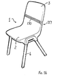
- the chair of the preferred embodiment is formed by a moulded plastics shell 1 having a seat 2 and a backrest 3.
- a moulded plastics shell 1 having a seat 2 and a backrest 3.
- Four tubular metal legs 4 are provided with the upper portion of the legs 4 being located within sockets (not illustrated) formed at the sides of the seat 2.
- the shell 1 is provided with a central opening 6 which separates the seat 2 from the backrest 3.
- a central opening 6 which separates the seat 2 from the backrest 3.
- a pair of moulded hinge arrangements 7 which interconnect the seat 2 and backrest 3.
- the underside of the seat 2 is provided with a plurality of strengthening ribs 8 which distribute the mechanical load of the weight of the sitter from the shell 1 and seat 2 to the legs 4.
- Figs. 4 and 5 in Fig. 4 the backrest 3 is illustrated in the rest position adopted in the absence of a sitter. However, as illustrated in Fig. 5 the backrest 3 is moveable into a rearwardly inclined position illustrated by full lines through the rearward movement of the back of a sitter (not illustrated). The rest position of the backrest 3 is illustrated by broken lines in Fig. 5.
- Figs. 6 and 7 illustrate the stacking ability of a plurality of the chairs of Figs. 1 to 5 whilst Fig. 8 illustrates a second embodiment in the form of an armchair developed from the side chair of Figs. 1 to 7.
- the armchair of Fig. 8 has a pair of armrests 9.
- each of the hinge arrangements 7 located to either side of the central opening 6 will now be described with reference to Figs. 9 to 15.
- the construction of each of the hinge arrangements 7 is substantially identical, however, only the hinge arrangement located to the left side of the chair is illustrated in detail.
- the hinge arrangement 7 is substantially formed from two parts.
- the major part is a recess 10 formed in the shell 1 which opens rearwardly and receives a hinge insert 11.
- the hinge insert 11 is maintained in the recess 10 by means of a fastener 12 which passes through a central aperture 13 in the insert 11 and is received in a boss 14 formed in the interior of the recess 10.
- the insert 11 has an upwardly directed, substantially rectangular protrusion 16 which is received in a downwardly directed slot 17 formed in the shell 1.
- the slot 17 is best seen in Fig. 11 and is indicated by broken lines in Fig. 9.
- a pair of opposed shelves 18 Within the recess 10, and adjacent the lower end thereof, are located a pair of opposed shelves 18. Between the shelves 18 and the upper surface 19 of a cross bar 20, is a space 21 which is shaped to receive a forwardly directed ledge 22 formed on the underside of the insert 11.
- a substantially vertically extending groove 24 is located in the recess 10 and is shaped to receive a length of wire 25 if additional stiffening is required for the hinge arrangement 7. Where a lesser degree of stiffening or resilience for the hinge arrangement 7 will suffice, the wire 25 can be omitted.
- the sides of the recess 10 are generally U-shaped as indicated at 26 and correspond in shape with generally C-shaped side portions 27 on the hinge insert 11. A sufficient gap is left between the side portions 27 and the U-shaped sides 26 in order to prevent clothing or fingers being accidentally pinched in the gap between these parts as the backrest 3 flexes with respect to the seat 2.
- Figs. 11 and 12 respectively show the backrest in the rest position and the rearwardly inclined position.
- flexure of the shell 1 at the location of the hinge arrangement 7 is permitted, and a plurality of transverse grooves 30 in the forward surface of the shell 1 assist this flexure.
- the flexure is permitted to accommodate the intended rearward direction of the backrest 3 until such time as a rearward stop position is reached, as illustrated in Fig. 12.
- a natural resilience for the hinge arrangement 7 is provided by means of the flexure of that portion of the shell 1 which includes the hinge arrangement 7, as the backrest 3 moves rearwardly. Additional resilience can be provided by means of the wire 25 which is deformed from its initial straight position, into a rearwardly facing curved position (not illustrated) as the backrest 3 moves into the position illustrated in Fig. 12. Further details of the hinge insert 11 is illustrated in Figs. 13 to 15.
- the above-described hinge arrangement provides a number of very important advantages. Because of the stops inherent in the forward or rest position of the backrest 3, the shell 1 is not liable to be damaged by a person sitting behind the chair and moving the backrest forwardly since such forward motion is strongly resisted. Similarly, the stops inherent in the rearwardly inclined position prevent the backrest 3 being bent rearwardly by such a person. Furthermore, the easy movement of the backrest 3 between the two positions illustrated in Figs. 11 and 12 means that a sitter experiences an easy "give" to the backrest but a firm stop is experienced at the position of maximum rearward inclination.
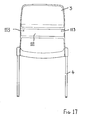
- a single hinge arrangement 117 is provided which extends across the width of the backrest 3.
- the hinge insert 111 is similarly extended in width and retained in place by two fasteners (not illustrated) which are each received in one of a corresponding pair of apertures 113.
- the hinge 117 of Figs. 16 and 17 is substantially similar to the hinge 7 of Figs. 9 to 12.
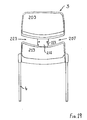
- a chair of a fourth embodiment again having only a single hinge 27 is illustrated.
- the upper portion 203 of the backrest 3 is separated from the lower portion 213 of the backrest 3 by a waisted portion 223 which comprises the hinge arrangement 207 interconnecting the two portions 203, 213 of the backrest 3.
- the grooves 230 extend across the front of waisted portion 223.
- the insert 211 also extends across the waisted portion 223 and is provided with a pair of apertures 113 as in Fig. 17.
- the hinge arrangement 207 is substantially similar to the hinge arrangement 117.
Abstract
Description
- The present invention relates to chairs and, in particular, to a moulded plastics chair in which the backrest and seat are moulded as a single shell and, in addition, the backrest is flexible with respect to the seat.
- Plastics chairs in which the seat and backrest are moulded as a single shell are well known, the chair normally being provided with metal legs. In some instances where the shell is not itself very strong, the shell is mounted on a metal frame which transfers the weight of the sitter from the shell to the legs.
- A moulded plastics shell incorporating both the seat and the backrest has many advantages in the manufacture of chairs, particularly in relation to reducing the cost of the chair and reducing the time taken by, and complexity of, the assembly procedures. In manufacturing such chairs, it has hitherto been highly desirable to avoid the backrest being flexible with respect to the seat. Where a metal frame has been provided, such flexibility is substantially negligible. However, where a metal frame is not provided for the shell, there will be some small degree of flexibility between the seat and the backrest. However, this flexibility arises merely because of the flexibility of the material used to fabricate the shell and is not the result of a specific constructional feature of the shell. In addition, because of the tendency of some plastics to fatigue with repeated flexure, such flexibility is undesirable and tends to shorten the life of the shell.
- It is also desirable in the manufacture of chairs if a chair can be provided in which the backrest is flexible with respect to the seat and able to be rearwardly inclined in an anatomically correct manner by the rearward movement of the back of a sitter about a horizontal axis located adjacent the lower portion of the back of the sitter. Such a chair has more "give" and is therefore more comfortable, particularly where the sitter remains seated for long periods. Many constructions have been proposed in order to provide for this desired flexibility, however, such arrangements are fabricated with the backrest and the seat being maae as separate pieces and being interconnected by a separate resilient hinge arrangement often ot complex mechanical construction.
- It is the object of the present invention to provide a moulded plastics chair in which the seat and backrest are moulded as a single shell and which, in addition, provides for flexibility of the backrest relative to this seat through the action of a constructional feature moulded into the shell.
- According to one aspect of the present invention there is disclosed a moulded plastics chair having a seat and a backrest moulded as a single shell with said backrest being connected to said seat by a resilient hinge means substantially moulded together with said shell; wherein said backrest is moveable by the action of said hinge means between a rest position adopted by the backrest in the absence of a sitter, and a rearwardly inclined position into which said backrest is resiliently urged by rearward movement of the back of a sitter.
- One embodiment of the present invention will now be described with reference to the drawings in which:
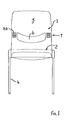
- Fig. 1 is a front elevation of the chair of the preferred embodiment,
- Fig. 2 is a rear elevation of the chair of Fig. 1.
- Fig. 3 is an inverted plan view of the chair of Fig. 1.
- Fig. 4 is a left side elevation of the chair of Fig. 1. the right side elevation being a mirror image thereof,
- Fig. 5 is a view similar to Fig. 4 but showing the backrest in the rearwardly inclined position, the rest position being illustrated by means of broken lines,
- Fig. 6 is a front elevation of two of the chairs of Fig. 1 stacked one above the other,
- Fig. 7 is a left side elevation of the two chairs of Fig. 6.
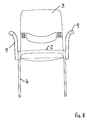
- Fig. 8 is a front elevation of a chair of a second embodiment having arms,
- Fig. 9 is a rear elevation of the left hand hinge arrangement of the chair of Fig. 1. but with the hinge insert absent,
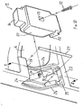
- Fig. 10 is an exploded perspective view of the hinge arrangement of Fig. 9.
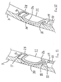
- Fig. 11 is a cross-sectional view taken along the line II-II of Fig. 10 and showing the backrest in its rest position,
- Fig. 12 is a view similar to Fig. 11 but showing the backrest in its rearwardly inclined position,
- Fig. 13 is a rear elevation of the hinge insert illustrated in Fig. 10 the insert being inclined,
- Fig. 14 is a front elevation of the inclined hinge insert of Fig. 13,
- Fig. 15 is a side elevation of the inclined hinge insert of Fig. 13,
- Fig. 16 is a left front perspective view of a chair of a third embodiment having a single hinge arrangement,
- Fig. 17 is a rear elevation of the chair of Fig. 16,
- Fig. 18 is a left front perspective view of a chair of a fourth embodiment having a single hinge arrangement, and
- Fig. 19 is a rear elevation of the chair of Fig. 18.
- As best seen in Figs. 1 to 4, the chair of the preferred embodiment is formed by a
moulded plastics shell 1 having aseat 2 and abackrest 3. Fourtubular metal legs 4 are provided with the upper portion of thelegs 4 being located within sockets (not illustrated) formed at the sides of theseat 2. - The
shell 1 is provided with acentral opening 6 which separates theseat 2 from thebackrest 3. To either side of thecentral opening 6 is one of a pair ofmoulded hinge arrangements 7 which interconnect theseat 2 andbackrest 3. As best seen in Fig. 3, the underside of theseat 2 is provided with a plurality of strengtheningribs 8 which distribute the mechanical load of the weight of the sitter from theshell 1 andseat 2 to thelegs 4. - Turning now to Figs. 4 and 5, in Fig. 4 the
backrest 3 is illustrated in the rest position adopted in the absence of a sitter. However, as illustrated in Fig. 5 thebackrest 3 is moveable into a rearwardly inclined position illustrated by full lines through the rearward movement of the back of a sitter (not illustrated). The rest position of thebackrest 3 is illustrated by broken lines in Fig. 5. - Figs. 6 and 7 illustrate the stacking ability of a plurality of the chairs of Figs. 1 to 5 whilst Fig. 8 illustrates a second embodiment in the form of an armchair developed from the side chair of Figs. 1 to 7. The armchair of Fig. 8 has a pair of
armrests 9. - The construction of the
hinge arrangement 7 located to either side of thecentral opening 6 will now be described with reference to Figs. 9 to 15. The construction of each of thehinge arrangements 7 is substantially identical, however, only the hinge arrangement located to the left side of the chair is illustrated in detail. - As best seen in Fig. 10. the
hinge arrangement 7 is substantially formed from two parts. The major part is a recess 10 formed in theshell 1 which opens rearwardly and receives ahinge insert 11. Thehinge insert 11 is maintained in the recess 10 by means of afastener 12 which passes through acentral aperture 13 in theinsert 11 and is received in aboss 14 formed in the interior of the recess 10. - The
insert 11 has an upwardly directed, substantiallyrectangular protrusion 16 which is received in a downwardly directedslot 17 formed in theshell 1. Theslot 17 is best seen in Fig. 11 and is indicated by broken lines in Fig. 9. As best seen in Fig. 10, within the recess 10, and adjacent the lower end thereof, are located a pair ofopposed shelves 18. Between theshelves 18 and theupper surface 19 of across bar 20, is aspace 21 which is shaped to receive a forwardly directedledge 22 formed on the underside of theinsert 11. - A substantially vertically extending
groove 24 is located in the recess 10 and is shaped to receive a length ofwire 25 if additional stiffening is required for thehinge arrangement 7. Where a lesser degree of stiffening or resilience for thehinge arrangement 7 will suffice, thewire 25 can be omitted. The sides of the recess 10 are generally U-shaped as indicated at 26 and correspond in shape with generally C-shaped side portions 27 on thehinge insert 11. A sufficient gap is left between theside portions 27 and theU-shaped sides 26 in order to prevent clothing or fingers being accidentally pinched in the gap between these parts as thebackrest 3 flexes with respect to theseat 2. - The operation of the
hinge arrangement 7 is best understood with reference to Figs. 11 and 12 which respectively show the backrest in the rest position and the rearwardly inclined position. - In the rest position illustrated in Fig. 11, the rear surface of the
protrusion 16 abutts the forward surface of a downwardlyinclined lip 28. In addition, the upper surface of theledge 22 is abutting the lower surfaces of theshelves 18. In this way, two stop limits for the forward movement of thebackrest 3 are provided. - As seen in Fig. 12, when the
backrest 3 is pushed rearwardly, flexure of theshell 1 at the location of thehinge arrangement 7 is permitted, and a plurality oftransverse grooves 30 in the forward surface of theshell 1 assist this flexure. The flexure is permitted to accommodate the intended rearward direction of thebackrest 3 until such time as a rearward stop position is reached, as illustrated in Fig. 12. - In the rearward stop position, a forward surface of the
protrusion 16 now abutts the forward surface of theslot 17. In addition, theupper surface 19 of thecross bar 20 also comes into contact with thehinge insert 11, as do the upper surfaces of theshelves 18. - A natural resilience for the
hinge arrangement 7 is provided by means of the flexure of that portion of theshell 1 which includes thehinge arrangement 7, as thebackrest 3 moves rearwardly. Additional resilience can be provided by means of thewire 25 which is deformed from its initial straight position, into a rearwardly facing curved position (not illustrated) as thebackrest 3 moves into the position illustrated in Fig. 12. Further details of thehinge insert 11 is illustrated in Figs. 13 to 15. - It will be appreciated that the above-described hinge arrangement provides a number of very important advantages. Because of the stops inherent in the forward or rest position of the
backrest 3, theshell 1 is not liable to be damaged by a person sitting behind the chair and moving the backrest forwardly since such forward motion is strongly resisted. Similarly, the stops inherent in the rearwardly inclined position prevent thebackrest 3 being bent rearwardly by such a person. Furthermore, the easy movement of thebackrest 3 between the two positions illustrated in Figs. 11 and 12 means that a sitter experiences an easy "give" to the backrest but a firm stop is experienced at the position of maximum rearward inclination. - It will also be appreciated that the above-described arrangement of a pair of hinges located one to either side of the backrest with an opening located between the hinges, is not the only way of constructing a chair in accordance with the present invention. In particular, it will be appreciated that the desired flexing ability of the
backrest 3 can be achieved with a single hinge arrangement as illustrated in Figs. 16 to 19. - In the chair of the third embodiment of Figs. 16 and 17, a
single hinge arrangement 117 is provided which extends across the width of thebackrest 3. Thehinge insert 111 is similarly extended in width and retained in place by two fasteners (not illustrated) which are each received in one of a corresponding pair ofapertures 113. In all other respects thehinge 117 of Figs. 16 and 17 is substantially similar to thehinge 7 of Figs. 9 to 12. Thegrooves 30 of Figs. 11 and 12, for example, now extend asgrooves 130 across the width of thebackrest 3. - Turning now to Figs. 18 and 19, a chair of a fourth embodiment, again having only a
single hinge 27 is illustrated. In this embodiment theupper portion 203 of thebackrest 3 is separated from thelower portion 213 of thebackrest 3 by awaisted portion 223 which comprises thehinge arrangement 207 interconnecting the twoportions backrest 3. Again thegrooves 230 extend across the front ofwaisted portion 223. Theinsert 211 also extends across thewaisted portion 223 and is provided with a pair ofapertures 113 as in Fig. 17. In all other respects, apart of a reduced length, thehinge arrangement 207 is substantially similar to thehinge arrangement 117. - The foregoing describes only some embodiments of the present invention and modifications, obvious to those skilled in the art, can be made thereto without departing from the scope of the present invention.
Claims (9)
Applications Claiming Priority (2)
| Application Number | Priority Date | Filing Date | Title |
|---|---|---|---|
| AU9777/85 | 1985-03-18 | ||
| AUPG977785 | 1985-03-18 |
Publications (2)
| Publication Number | Publication Date |
|---|---|
| EP0196819A2 true EP0196819A2 (en) | 1986-10-08 |
| EP0196819A3 EP0196819A3 (en) | 1987-05-20 |
Family
ID=3770982
Family Applications (1)
| Application Number | Title | Priority Date | Filing Date |
|---|---|---|---|
| EP86301969A Withdrawn EP0196819A3 (en) | 1985-03-18 | 1986-03-18 | Chair |
Country Status (4)
| Country | Link |
|---|---|
| US (1) | US4733910A (en) |
| EP (1) | EP0196819A3 (en) |
| JP (1) | JPS61253010A (en) |
| ZA (1) | ZA861983B (en) |
Cited By (9)
| Publication number | Priority date | Publication date | Assignee | Title |
|---|---|---|---|---|
| WO1987004909A1 (en) * | 1986-02-13 | 1987-08-27 | Hartmut Lohmeyer | Chair with a seat and an elastically yielding back support |
| FR2619496A1 (en) * | 1987-08-18 | 1989-02-24 | Massonnet Henry | SOFT BACK ARMCHAIR |
| WO1992012654A1 (en) * | 1991-01-20 | 1992-08-06 | Fritz Hansens Eft. A/S | Seat shell |
| US5887946A (en) * | 1997-01-03 | 1999-03-30 | Raftery Design, Inc. | Chair with movable back support |
| WO2009090271A1 (en) * | 2008-01-14 | 2009-07-23 | Resinas Olot, S.A. | Improved stacking chair |
| EP2460439A1 (en) * | 2010-12-01 | 2012-06-06 | Sebel Furniture Ltd | One piece plastic chair |
| WO2013025529A3 (en) * | 2011-08-12 | 2013-10-10 | Hni Technologies Inc. | Flexible back support member with integrated recline stop notches |
| WO2014036043A1 (en) * | 2012-08-29 | 2014-03-06 | Hni Technologies, Inc. | Resilient chair incorporating multiple flex zones |
| US10799028B2 (en) | 2017-08-10 | 2020-10-13 | NHI Corporation | Chairs including flexible frames |
Families Citing this family (38)
| Publication number | Priority date | Publication date | Assignee | Title |
|---|---|---|---|---|
| FR2620791B1 (en) * | 1987-09-22 | 1989-12-29 | Strafor Sa | DEFORMABLE STRUCTURE |
| US4869552A (en) * | 1988-09-14 | 1989-09-26 | Shelby Williams Industries, Inc. | Flexible backrest assembly for a chair |
| US5035467A (en) * | 1988-09-15 | 1991-07-30 | Pin Dot Products | Seating system |
| JPH0628046Y2 (en) * | 1989-12-21 | 1994-08-03 | タカノ株式会社 | Chair |
| US5100201A (en) * | 1990-09-21 | 1992-03-31 | J.G. Furniture Systems Inc. | Passive ergonomic work chair |
| US5415461A (en) * | 1993-10-29 | 1995-05-16 | Sakamoto; Alice | Furniture construction |
| DE4427754C2 (en) * | 1994-08-05 | 1997-09-11 | Mauser Office Gmbh | Chair, especially swivel chair |
| USD463144S1 (en) | 2000-09-28 | 2002-09-24 | Formway Furniture Limited | Chair |
| USD445580S1 (en) | 2000-09-28 | 2001-07-31 | Formway Furniture Limited | Chair |
| AU783829B2 (en) | 2000-09-28 | 2005-12-08 | Formway Furniture Limited | A reclinable chair |
| AUPR054400A0 (en) | 2000-09-29 | 2000-10-26 | Formway Furniture Limited | A castor |
| US6722735B2 (en) * | 2001-04-16 | 2004-04-20 | Ditto Sales, Inc. | Chair with synchronously moving seat and seat back |
| JP4855593B2 (en) * | 2001-06-28 | 2012-01-18 | 株式会社岡村製作所 | Chair shell structure |
| US7040637B2 (en) * | 2001-10-12 | 2006-05-09 | Invacare Corporation | Inwardly folding rollator with an upwardly pivotable seat |
| MY134768A (en) * | 2002-01-17 | 2007-12-31 | Green Continental Furniture M Sdn Bhd | A dining chair with reclining mechanism |
| NZ518944A (en) * | 2002-05-14 | 2004-09-24 | Formway Furniture Ltd | Height adjustable arm for chair with outer stem releasably lockable to inner stem by engagement of recesses |
| GB0323432D0 (en) * | 2003-10-07 | 2003-11-05 | Ellis Gordon & Co | Seating assemblies |
| DE602004004359T2 (en) * | 2004-01-26 | 2007-08-23 | Pro-Cord S.P.A. | Chair with tilting backrest |
| JP2006204801A (en) * | 2005-01-31 | 2006-08-10 | Itoki Corp | Chair and backrest cushion body used for the same |
| EP2019609B1 (en) | 2006-04-28 | 2011-03-16 | Steelcase Inc. | Seating construction and method of assembly |
| DE602006014274D1 (en) * | 2006-09-18 | 2010-06-24 | Pro Cord Spa | Seat backrest with integrated lumbar support |
| ATE425685T1 (en) * | 2007-02-01 | 2009-04-15 | Pro Cord Spa | CHAIR WITH DEFORMABLE BACKREST |
| WO2009134451A1 (en) | 2008-05-02 | 2009-11-05 | Haworth, Inc. | Tension mechanism for a weight-responsive chair |
| US20100244515A1 (en) * | 2009-03-31 | 2010-09-30 | Dragomir Ivicevic | Reclining Chair |
| US8540315B2 (en) * | 2010-01-21 | 2013-09-24 | Pro-Cord S.P.A. | Nestable chair with seat rotation and stop arrangement |
| ITTO20110375A1 (en) * | 2011-04-29 | 2012-10-30 | Pro Cord Spa | CHAIR WITH OSCILLATING BACKREST |
| JP5953738B2 (en) * | 2011-12-27 | 2016-07-20 | コクヨ株式会社 | Chair |
| US9504326B1 (en) | 2012-04-10 | 2016-11-29 | Humanscale Corporation | Reclining chair |
| US9072384B2 (en) | 2013-03-08 | 2015-07-07 | Smith System | Multi-directional body motion stack chair |
| ITUB20150149A1 (en) * | 2015-02-17 | 2016-08-17 | Pro Cord Spa | Chair with swing seat |
| BR112017022038B1 (en) | 2015-04-13 | 2021-11-03 | Steelcase Inc. | SEAT ARRANGEMENT |
| US10966527B2 (en) | 2017-06-09 | 2021-04-06 | Steelcase Inc. | Seating arrangement and method of construction |
| US10194750B2 (en) | 2015-04-13 | 2019-02-05 | Steelcase Inc. | Seating arrangement |
| US11259637B2 (en) | 2015-04-13 | 2022-03-01 | Steelcase Inc. | Seating arrangement |
| USD760525S1 (en) * | 2015-04-21 | 2016-07-05 | Pro-Cord S.P.A. | Chair |
| USD761606S1 (en) * | 2015-04-21 | 2016-07-19 | Pro-Cord S.P.A. | Two-color chair |
| USD764849S1 (en) * | 2015-04-21 | 2016-08-30 | Pro-Cord S.P.A. | Chair |
| IT202100014576A1 (en) * | 2021-06-04 | 2022-12-04 | Pro Cord Spa | Chair with flexible backrest |
Citations (3)
| Publication number | Priority date | Publication date | Assignee | Title |
|---|---|---|---|---|
| FR2032061A5 (en) * | 1969-02-17 | 1970-11-20 | Stamp | |
| FR2313889A1 (en) * | 1975-06-13 | 1977-01-07 | Fehlbaum Fa | FUNCTIONAL CHAIR |
| FR2443226A1 (en) * | 1978-12-04 | 1980-07-04 | Center Design Res & Dev | CHAIR |
Family Cites Families (5)
| Publication number | Priority date | Publication date | Assignee | Title |
|---|---|---|---|---|
| US3031227A (en) * | 1960-08-04 | 1962-04-24 | Charleston Molded Fiber Glass | Chair |
| US3669496A (en) * | 1970-12-03 | 1972-06-13 | American Desk Mfg Co | Chair and seat and back unit therefor |
| CH623523A5 (en) * | 1977-09-09 | 1981-06-15 | Alusuisse | Shell for a seat device, in particular for a vehicle seat |
| DE8135614U1 (en) * | 1981-12-07 | 1983-11-10 | Gebr. Thonet GmbH, 6000 Frankfurt | SEAT FURNITURE |
| US4529247A (en) * | 1982-04-15 | 1985-07-16 | Herman Miller, Inc. | One-piece shell chair |
-
1986
- 1986-03-17 US US06/840,348 patent/US4733910A/en not_active Expired - Lifetime
- 1986-03-18 ZA ZA861983A patent/ZA861983B/en unknown
- 1986-03-18 JP JP61058441A patent/JPS61253010A/en active Pending
- 1986-03-18 EP EP86301969A patent/EP0196819A3/en not_active Withdrawn
Patent Citations (3)
| Publication number | Priority date | Publication date | Assignee | Title |
|---|---|---|---|---|
| FR2032061A5 (en) * | 1969-02-17 | 1970-11-20 | Stamp | |
| FR2313889A1 (en) * | 1975-06-13 | 1977-01-07 | Fehlbaum Fa | FUNCTIONAL CHAIR |
| FR2443226A1 (en) * | 1978-12-04 | 1980-07-04 | Center Design Res & Dev | CHAIR |
Cited By (17)
| Publication number | Priority date | Publication date | Assignee | Title |
|---|---|---|---|---|
| WO1987004909A1 (en) * | 1986-02-13 | 1987-08-27 | Hartmut Lohmeyer | Chair with a seat and an elastically yielding back support |
| FR2619496A1 (en) * | 1987-08-18 | 1989-02-24 | Massonnet Henry | SOFT BACK ARMCHAIR |
| EP0305303A1 (en) * | 1987-08-18 | 1989-03-01 | Societe Dite "Stamp" | Armchair with a flexible backrest |
| WO1992012654A1 (en) * | 1991-01-20 | 1992-08-06 | Fritz Hansens Eft. A/S | Seat shell |
| US5340197A (en) * | 1991-01-20 | 1994-08-23 | Fritz Hansen A/S | One-piece seat shell |
| US5887946A (en) * | 1997-01-03 | 1999-03-30 | Raftery Design, Inc. | Chair with movable back support |
| US5988746A (en) * | 1997-01-03 | 1999-11-23 | Raferty Design, Inc. | Split back chair |
| WO2009090271A1 (en) * | 2008-01-14 | 2009-07-23 | Resinas Olot, S.A. | Improved stacking chair |
| EP2460439A1 (en) * | 2010-12-01 | 2012-06-06 | Sebel Furniture Ltd | One piece plastic chair |
| CN102525164A (en) * | 2010-12-01 | 2012-07-04 | 塞贝尔家具有限公司 | One piece plastic chair |
| WO2013025529A3 (en) * | 2011-08-12 | 2013-10-10 | Hni Technologies Inc. | Flexible back support member with integrated recline stop notches |
| CN103813735A (en) * | 2011-08-12 | 2014-05-21 | Hni技术公司 | Flexible back support member with integrated recline stop notches |
| CN103813735B (en) * | 2011-08-12 | 2016-11-09 | Hni技术公司 | The flexible back support component of stop notch is leaned on after there is integration |
| US9572432B2 (en) | 2011-08-12 | 2017-02-21 | Hni Corporation | Flexible back support member with integrated recline stop notches |
| WO2014036043A1 (en) * | 2012-08-29 | 2014-03-06 | Hni Technologies, Inc. | Resilient chair incorporating multiple flex zones |
| US8820835B2 (en) | 2012-08-29 | 2014-09-02 | Hni Technologies Inc. | Resilient chair incorporating multiple flex zones |
| US10799028B2 (en) | 2017-08-10 | 2020-10-13 | NHI Corporation | Chairs including flexible frames |
Also Published As
| Publication number | Publication date |
|---|---|
| EP0196819A3 (en) | 1987-05-20 |
| ZA861983B (en) | 1987-10-28 |
| US4733910A (en) | 1988-03-29 |
| JPS61253010A (en) | 1986-11-10 |
Similar Documents
| Publication | Publication Date | Title |
|---|---|---|
| US4733910A (en) | Article of furniture | |
| US5123702A (en) | Interaction-high density stacking chair | |
| KR102283013B1 (en) | Portable chair | |
| US8820835B2 (en) | Resilient chair incorporating multiple flex zones | |
| US5411316A (en) | Single piece chair shell | |
| US5318346A (en) | Chair with zero front rise control | |
| CA2345603C (en) | Chair with synchronously moving seat and seat back | |
| NL7908756A (en) | CHAIR. | |
| US7021712B2 (en) | Chair with flexible, resilient back support | |
| US4660887A (en) | Ergonomic support | |
| US4869552A (en) | Flexible backrest assembly for a chair | |
| US5868468A (en) | Chair with adjustable inclination | |
| EP2092855A1 (en) | Backrest device for chair | |
| US20040140701A1 (en) | Backrest for a seating structure with an adjustable sacral support | |
| MX2008012204A (en) | Ergonomic side chair. | |
| CA2663687A1 (en) | Synchrotilt chair with adjustable seat, back and energy mechanism | |
| US4316632A (en) | Ergonomic chair | |
| US5697673A (en) | Chair with a pivoting backrest | |
| US4856845A (en) | Armchair with supple backrest | |
| KR102130324B1 (en) | Assembly and chair with the same | |
| US4046422A (en) | Chair | |
| US4159146A (en) | Chairs | |
| WO1991003192A1 (en) | Concealed flexible backrest frame assembly for a chair | |
| WO1996010937A1 (en) | Chair seat | |
| EP4059381A1 (en) | A chair with pivoting seat and backrest |
Legal Events
| Date | Code | Title | Description |
|---|---|---|---|
| PUAI | Public reference made under article 153(3) epc to a published international application that has entered the european phase |
Free format text: ORIGINAL CODE: 0009012 |
|
| AK | Designated contracting states |
Kind code of ref document: A2 Designated state(s): DE GB IT |
|
| PUAL | Search report despatched |
Free format text: ORIGINAL CODE: 0009013 |
|
| AK | Designated contracting states |
Kind code of ref document: A3 Designated state(s): DE GB IT |
|
| 17P | Request for examination filed |
Effective date: 19871109 |
|
| 17Q | First examination report despatched |
Effective date: 19890117 |
|
| STAA | Information on the status of an ep patent application or granted ep patent |
Free format text: STATUS: THE APPLICATION IS DEEMED TO BE WITHDRAWN |
|
| 18D | Application deemed to be withdrawn |
Effective date: 19910321 |
|
| RIN1 | Information on inventor provided before grant (corrected) |
Inventor name: BRENNAN, JAMES WILLIAM |