EP0196692A1 - Card holder - Google Patents
Card holder Download PDFInfo
- Publication number
- EP0196692A1 EP0196692A1 EP86200315A EP86200315A EP0196692A1 EP 0196692 A1 EP0196692 A1 EP 0196692A1 EP 86200315 A EP86200315 A EP 86200315A EP 86200315 A EP86200315 A EP 86200315A EP 0196692 A1 EP0196692 A1 EP 0196692A1
- Authority
- EP
- European Patent Office
- Prior art keywords
- spring
- contact
- card
- holder
- holder according
- Prior art date
- Legal status (The legal status is an assumption and is not a legal conclusion. Google has not performed a legal analysis and makes no representation as to the accuracy of the status listed.)
- Withdrawn
Links
Images


Classifications
-
- H—ELECTRICITY
- H01—ELECTRIC ELEMENTS
- H01R—ELECTRICALLY-CONDUCTIVE CONNECTIONS; STRUCTURAL ASSOCIATIONS OF A PLURALITY OF MUTUALLY-INSULATED ELECTRICAL CONNECTING ELEMENTS; COUPLING DEVICES; CURRENT COLLECTORS
- H01R9/00—Structural associations of a plurality of mutually-insulated electrical connecting elements, e.g. terminal strips or terminal blocks; Terminals or binding posts mounted upon a base or in a case; Bases therefor
-
- H—ELECTRICITY
- H01—ELECTRIC ELEMENTS
- H01R—ELECTRICALLY-CONDUCTIVE CONNECTIONS; STRUCTURAL ASSOCIATIONS OF A PLURALITY OF MUTUALLY-INSULATED ELECTRICAL CONNECTING ELEMENTS; COUPLING DEVICES; CURRENT COLLECTORS
- H01R12/00—Structural associations of a plurality of mutually-insulated electrical connecting elements, specially adapted for printed circuits, e.g. printed circuit boards [PCB], flat or ribbon cables, or like generally planar structures, e.g. terminal strips, terminal blocks; Coupling devices specially adapted for printed circuits, flat or ribbon cables, or like generally planar structures; Terminals specially adapted for contact with, or insertion into, printed circuits, flat or ribbon cables, or like generally planar structures
- H01R12/70—Coupling devices
- H01R12/71—Coupling devices for rigid printing circuits or like structures
- H01R12/72—Coupling devices for rigid printing circuits or like structures coupling with the edge of the rigid printed circuits or like structures
- H01R12/721—Coupling devices for rigid printing circuits or like structures coupling with the edge of the rigid printed circuits or like structures cooperating directly with the edge of the rigid printed circuits
Definitions
- the invention relates to credit and other cards with electronically stored data which can be read and printed circuit boards, and more particular to a holder provided with guide means to receive such cards.
- connection strips are preferably in the form of edge contacts.
- the object of the invention is to provide a holder of the type described above which avoid the above problem.
- each contact spring has a first spring end part which is adjacent to the movable end of the contact spring, an intermediate spring part and a second clamped spring end part serving as connection terminal; said first contact spring part being disposed substantially perpendicular tot the intermediate spring part, and said intermediate part being substantially perpendicular to the infeed plane of the holder; that the first spring part is spaced from the shifting plane of the connection strips; and that a stop element is located at the point where the first spring end part and the intermediate spring part join, said stop element extending from the plane of the first spring end part into the infeed plane of the holder.
- the contact spring parts and their respective stop elements are preferably bent from one piece.
- the intermediate spring part continues past the first spring end part and, after successively bending back through 180 degrees and bending through 90 degrees, the intermediate spring part merges into the first.
- the stop element is formed by at leasdt one extension piece of the intermediate spring part continuing along the first spring end part.
- An embodiment which is particularly suitable for adjustment of the contact spring is characterized in that the extension piece is bent in the direction of the first spring part along a bending line which runs substantially parallel to the center line of the intermediate spring part. Adjustment of the contact pressure takes place by setting the width of the extension piece or the angle thereof relative to the intermediate spring part.
- the end of the first spring part is bent back through less than 180 degrees and can make contact with a connection strip of an inserted card.
- the intermediate spring part after successively bending back through 180 degrees and bending through 90 degrees, merges into the second spring end part which is parallel to the first spring part.
- the contact springs cannot be soldered in customary fashion into a plate with printed wiring.
- An embodiment which solves this problem is cahracterised in that the second contact spring part is provided at the clamped end with forced-out points. When these points have been pushed through a ribbon cable, they are bent back against the ribbon cable. This procudes a reliable contact between contact spring and a conductor of the ribbon cable.
- each contact spring has a first spring end part which is adjacent to the movable end of the contact spring, an intermediate spring part bent into a U-shape and a second clamped spring end part serving as connection terminal, in which the one and the other legs of the U join the first and second spring end parts respectively, said first spring part being disposed substantially perpendicular to the intermediate spring, part, and said intermediate part being substantially perpendicular to the infeed plane of the holder; that a stop element is located at the point where the first spring end part and the intermediate spring part join, said stop element extending from the plane of the first spring end part into the infeed plane of the holder; that in the rest condition, the legs of the intermediate spring part converge slightly to each other in the direction of their ends; that the first spring end part extends slantingly past the shifting plane of the connection strips of the card; that a biasing rod
- An embodiment according to the second aspect of the invention is characterized in that one or more first spring end parts are pre-bent to the infeed plane of the card more as to the remaining first spring end parts, so that the contact points thereof make earlier respectively disconnect later the contact with the contacting strips of the card than the contact points of the said remaining end parts when the rod is rotated by a fourth of one revolution for making respectively disconnecting the contact.
- a further embodiment is characterized in that the second spring end parts extend in upright position from the other U-leg of the contact springs through the bottom of the connector and project parallel to each other out of the connector at the side facing from the insert side.
- Yet a further embodiment of the invention is characterized in that the contact springs are separated from each other by insulating partitions accomodated in the connector.
- the connector is provided with a non-conductive support located between the first spring end parts and the infeed plane of the holder and presenting a support face parallel to the holder infeed plane for supporting the said end parts in the rest position, that the said support has at its free end facing to the intermediate spring parts an inclined race for the first spring parts; and that the tip of said first spring end parts extends under an acute angle as to the support face.
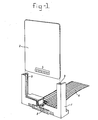
- Fig. 1 illustrates a card reader holder 1, above which is a card 2 to be inserted.
- the card may be an identity or credit card or the like.
- connection strips 4 in the form of edge contacts, which are connected to a memory chip or other similar integrated circuit (not illustrated).
- the card reader holder 1 is provided with guide grooves 3 for the card 2 to be inserted.
- the clamped end of the contact spring 4 is connected to a conductor of the ribbon cable 6, which in turn is connected to the reader device (not shown).
- Fig. 2a to 2d show different embodiments of the contact spring 5.
- the contact springs consist of two parts 7 and 8 which are at right angles to each other.
- the first contact spring part 7 has a contact face 9 which canes to rest against an edge contact 4 of an inserted card 2 and makes contact with it.
- the second contact spring part 8 of the embodiments shown in Figs. 2a, 2b and 2c is clamped in the holder.
- the contact spring can be clamped by means of a soldering connection pin 10.
- the contact springs of Figs. 2a to 2d all have a stop element 11, which an inserted card comes up against.
- the stop element 11 Fig. 2a is formed by an extension piece 12 of the second contact spring part 8, which is bent back through 180 degrees and, after a bend of virtually 90 degrees, merges into the first contact
- extension pieces 13 of contact spring part 8 use is made of two extension pieces 13 of contact spring part 8. Extension pieces 13 run through on either side of the contact spring part 7. These extension pieces 13 serve as the stop element 11 for the card 2 to be inserted. Although two extension pieces 13 are shown here, one could do with one extension piece if necessary. Owing to the fact that two extension pieces 13 are used here, tilting of the contact spring part 7 in its plane is avoided.
- the contact spring of Fig. 2b has only one extension piece 14 as a stop element, which is bent along the bending line 15 in the direction of the contact spring part 7.
- the pressure of the contact face 9 against an edge contact of an inserted card can be adjusted by setting the dimension of the extension piece 14 in the direction of the contact spring part 7, or by setting the angle of the extension piece 14 relative to the contact spring part 8.
- the contact springs consist of two parts 7 and 8, at right angles to each other with a stop element 11 near the transition point, when the card 2 is inserted to a particular depth its front edge will come up against the stop element.
- the clamped part 8 undergoes angular rotation.
- the other contact spring part 7 thereby undergoes a displacement and is pressed with increasing pressure against the edge contacts 4 of the card 2, without the contact point between edge contact and contact spring shifting in relation to the edge contact or contact spring face 9.
- the contact pressure will be determined dependent on the vertical displacement of the card and thus of the contact spring parts 7 and 8.
- the card 2 On insertion, the card 2 is guided in the guide grooves 3 for this purpose, so that the card undergoes no horizontal displacement. It is clear that during insertion of the card 2 wear is restricted to a minimum through the fact that the abovementioned contact point undergoes no relative displacement when the contact pressure is being built up.
- openings are provided in the bottom of the guide holder, so that no accumulation of dust can occur.
- the clamped contact spring part 8 is provided on its end with forced-out points 16 such as shown in Fig. 2a. It can be seen from Figs. 3a and 3b that this connection is produced by the sharp points 16 being pressed through the film of the ribbon cable and then being flanged back. The connection thereby obtained is produced at four points 16 simultaneously, through these four points partially cut through the signal track. An important part for the signal transmission is still present, particularly in the center of the shrink connection.
- the displacement of the partially cut away film has caused the central part to bulge out and, with a force developed in the process, to lie against the inner side of the contact points.
- the film is cut through by rigid material parts and is subsequently deformed in such a way that elastic action of the film on the metal parts is not possible anymore or inadequate.
- the contact spring according to Fig. 2d is provided with a soldering pin 10. It should also be said that the shape of the contact spring according to Fig. 2d will be important if the contacts are to be in line with the card 2.
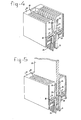
- Fig. 4 shows a perspective view of a cut out edge connector, in which a number of parallel spring members are accanodated for engaging contact faces at the insert edge of a printed circuit board.
- Each contact member consists of two individual opposing contact springs 21 and 22.
- Each contact spring consists of an intermediate spring part bent in an U-shape, one first spring end part 23 extending in upright position from the one U-leg and a second spring end part 24 implemented as contact pin and extending from the other U-leg.
- the second spring end parts are clamped in any suitable way in the bottom of the housing 18 0 f the edge connector. They may project both in upstanding position and parallel to each other fran the bottom and through the sidewalls in clamped condition out of the connector.
- the contact pressure is built up during inserting.
- the printed circuit board 19 its insert edge abuts against a fixed stop element provided by both of the rows of opposing stop lips 28 of the U-shaped intermediate spring parts of the contact springs 21,22.
- the contact points 26 of the contact springs will engage the opposing contact faces of the printed circuit board and a contact will result. Thereby no or nearly no relative displacements between both spots occur.
- the printed circuit board is locked now by means of an external locking device and thereby, is kept in its place. By unlocking the printed circuit board this will be pushed away by a common spring force from the individual contact springs, so that the printed circuit board may be removed readily.
- Figs. 6a and 6b present a front view of an individual contact spring member
- the inserting of the printed circuit board is realized without contact pressure or with zero force.
- the individual contact springs of each contact spring member are rebent such that the U-legs of the intermediate spring part of each contact spring converge in some extent to each other in unbiased condition and without inserted printed circuit board.
- a rod to be inserted and/or operated from the outside has been received between e.g. the bottom of the housing of the edge connector and both of the stop lips of the one legs of the intermediate spring parts.
- both of the U-legs and consequently also both of the first spring end parts 23 of both of the contact springs are bent from each other.
- the subsequent inserting of the insert edge of the printed circuit board it is not required to generate a force and the printed circuit board will ultimately rest against the row of both opposing stop lips.
- the biasing rod By rotating the biasing rod from the outside by a fourth of a revolution the contact points of both of the first spring end parts 23 will make contact to the contact faces of the printed circuit board without requirement of building up a contact force during inserting.
- By rotating the biasing rod by a fourth of a revolution for releasing the printed circuit board said board may be removed from a connector without a further force.
- the advantage of said second embodiment is that an additional locking of the printed circuit board is not required anymore. Furthermore, by the absence of the inserting force required otherwise, a higher number of contacts per connector may be employed, e.g. 2 x 200 contacts per connector having a mutual distance of 1.0 mm.
- one or more contact spring members as indicated in Fig. 7 may be prebent additionally so that the contact points thereof make earlier respectively disconnect later the contact with the contact faces of the printed circuit board (first make, last break) then the contact points of the remaining contact spring members.
- FIGs. 8a and b some different possible embodiments of the contact points of the individual contact springs are illustrated.
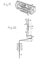
- Fig. 9 shows a further embodiment of a connector which may be used in e.g. a card reader holder or printed circuit board holder.
- Fig. 10 a detail of said connector is shown in cross-section.
- the connector is provided with a number of springs 21, 23, 24 for the connection with contact surfaces on a card of board to be inserted.
- the free ends 23 of the springs are supported by a support face of a support element 29.
- the intermediate part 21 of each spring is urged downwards and the free ends 23 of the springs slide from the support 29. Then the contacts 30 of the springs engage the corresponding connecting surfaces of the card.
- Fig. 10 the spring 21,23,24 is shown by a solid line in the rest position and by a dashed line in the operation condition.
Abstract
A holder for receiving cards with electronically stored data or printed circuit boards. The holder has guide means to receive the card. The holder is provided with a connector with contact springs for contacting connection strips located on the card. One end of each contact spring is clamped while the other is free to move and make contact with the connection strips. The contact springs include the parts formed by bending and shaped so as to minimize pressure and friction against the connection strips of the card.
Description
- The invention relates to credit and other cards with electronically stored data which can be read and printed circuit boards, and more particular to a holder provided with guide means to receive such cards.
- Automation in banking has led to electronic data processing of many banking functions. Automatic bank teller machines are now a common sight. Various banking transactions, including customer withdrawal, can be done at these machines by means of preceded cards such as credit cards.
- There is now the possibility of providing on such a card a memory chip by means of which personal data can be stored. This data can be read when the card is inserted into a guide groove of a holder intended for the purpose and when connection strips on the card contact contact springs disposed in the holder. The connection strips are preferably in the form of edge contacts.
- It is extremely important that the card should be usable many times without the edge contacts being damaged by the contact springs. Such damage occurs in existing cards because a certain contact pressure is necessary for reliable reading of the card. Consequently, friction occurring between the contact springs and connection strips, results in unacceptable wear.
- The object of the invention is to provide a holder of the type described above which avoid the above problem.
- This object is achieved according to the invention in that each contact spring has a first spring end part which is adjacent to the movable end of the contact spring, an intermediate spring part and a second clamped spring end part serving as connection terminal; said first contact spring part being disposed substantially perpendicular tot the intermediate spring part, and said intermediate part being substantially perpendicular to the infeed plane of the holder; that the first spring part is spaced from the shifting plane of the connection strips; and that a stop element is located at the point where the first spring end part and the intermediate spring part join, said stop element extending from the plane of the first spring end part into the infeed plane of the holder. One of the advantages achieved by this arrangement is that during the build-up of the contact pressure, the contact point between contact spring and connection strip undergoes no relative displacement.
- The contact spring parts and their respective stop elements are preferably bent from one piece. In an embodiment in which the contact spring is in one piece, the intermediate spring part continues past the first spring end part and, after successively bending back through 180 degrees and bending through 90 degrees, the intermediate spring part merges into the first.
- In another embodiment the stop element is formed by at leasdt one extension piece of the intermediate spring part continuing along the first spring end part.
- An embodiment which is particularly suitable for adjustment of the contact spring is characterized in that the extension piece is bent in the direction of the first spring part along a bending line which runs substantially parallel to the center line of the intermediate spring part. Adjustment of the contact pressure takes place by setting the width of the extension piece or the angle thereof relative to the intermediate spring part.
- According to another embodiment of the invention, the end of the first spring part is bent back through less than 180 degrees and can make contact with a connection strip of an inserted card.
- According to yet another embodiment, the intermediate spring part, after successively bending back through 180 degrees and bending through 90 degrees, merges into the second spring end part which is parallel to the first spring part.
- Since a card reader provided with the card holder is usually fitted on the outside of an apparatus, the contact springs cannot be soldered in customary fashion into a plate with printed wiring. An embodiment which solves this problem is cahracterised in that the second contact spring part is provided at the clamped end with forced-out points. When these points have been pushed through a ribbon cable, they are bent back against the ribbon cable. This procudes a reliable contact between contact spring and a conductor of the ribbon cable.
- The abovementioned object to provide a holder which avoids the friction between the contact springs and connection strips is achieved according to a second aspect of the invention in that each contact spring has a first spring end part which is adjacent to the movable end of the contact spring, an intermediate spring part bent into a U-shape and a second clamped spring end part serving as connection terminal, in which the one and the other legs of the U join the first and second spring end parts respectively, said first spring part being disposed substantially perpendicular to the intermediate spring, part, and said intermediate part being substantially perpendicular to the infeed plane of the holder; that a stop element is located at the point where the first spring end part and the intermediate spring part join, said stop element extending from the plane of the first spring end part into the infeed plane of the holder; that in the rest condition, the legs of the intermediate spring part converge slightly to each other in the direction of their ends; that the first spring end part extends slantingly past the shifting plane of the connection strips of the card; that a biasing rod having a substantially rectangular cross-section to be inserted and/or operated from outside is provided, said rod lying parallel to and between the stop elements and the bottom of the holder in the rest condition of the contact springs and when rotated by a fourth part of one revolution, the U-legs and so the first spring end parts are bent from the shifting plane of the connecting strips of the card, so that in the subsequent inserting of the card without contact pressure, said card abuts with its front edge against the stop elements of the contact springs, whereafter the biasing rod is newly rotated by a fourth of one revolution and then the contacting strips contact the contact points of the first end part of the springs.
- An embodiment according to the second aspect of the invention is characterized in that one or more first spring end parts are pre-bent to the infeed plane of the card more as to the remaining first spring end parts, so that the contact points thereof make earlier respectively disconnect later the contact with the contacting strips of the card than the contact points of the said remaining end parts when the rod is rotated by a fourth of one revolution for making respectively disconnecting the contact.
- A further embodiment is characterized in that the second spring end parts extend in upright position from the other U-leg of the contact springs through the bottom of the connector and project parallel to each other out of the connector at the side facing from the insert side.
- Yet a further embodiment of the invention is characterized in that the contact springs are separated from each other by insulating partitions accomodated in the connector.
- Another embodiment of the invention is characterized in that the connector is provided with a non-conductive support located between the first spring end parts and the infeed plane of the holder and presenting a support face parallel to the holder infeed plane for supporting the said end parts in the rest position, that the said support has at its free end facing to the intermediate spring parts an inclined race for the first spring parts;
and that the tip of said first spring end parts extends under an acute angle as to the support face. - The invention wil be explained further below with reference to the drawin. In the drawing:
- Fig. 1 is a perspective view showing a card reader holder according to the invention;
- Fig. 2a, b, c and d illustrate various schematic embodiments of a contact spring according to the invention.
- Fig. 3 shows an embodiment illustrating the contact between contact spring and a conductor of a ribbon cable.
- Fig. 4 is a perspective view of an embodiment of the invention for a printed circuit board.
- Fig. 5 shows a perspective view of the embodiment of fig. 4 in which the printed circuit board is inserted;
- Figs. 6a and 6b respectively illustrate a cross-section of another embodiment of the invention having a contact spring in unbiased and biased condition, in which the printed circuit board is inserted;
- Fig. 7 is a cross-section of one single contact spring being bent additionally;
- Fig. 8a and 8b show sane modifications of the contact points of a single contact spring;
- Fig. 9 illustrates another embodiment of the invention; and
- Fig. 10 is a detail of fig. 9.
- Fig. 1 illustrates a card reader holder 1, above which is a
card 2 to be inserted. The card may be an identity or credit card or the like. On thecard 2 are a number of connection strips 4 in the form of edge contacts, which are connected to a memory chip or other similar integrated circuit (not illustrated). - The card reader holder 1 is provided with
guide grooves 3 for thecard 2 to be inserted. On the underside of the card reader holder 1 there are a number ofcontact springs 5 which are clamped at one end in the holder. Through the removal of part of the holder, one of thecontact springs 5 is clearly visible. The other end of thecontact spring 5 is freely movable and will make contact with the edge contact 4 of the insertedcard 2. The clamped end of the contact spring 4 is connected to a conductor of theribbon cable 6, which in turn is connected to the reader device (not shown). - Fig. 2a to 2d show different embodiments of the
contact spring 5. The contact springs consist of twoparts contact spring part 7 has acontact face 9 which canes to rest against an edge contact 4 of an insertedcard 2 and makes contact with it. The secondcontact spring part 8 of the embodiments shown in Figs. 2a, 2b and 2c is clamped in the holder. In the embodiment of Fig. 2d, the contact spring can be clamped by means of asoldering connection pin 10. The contact springs of Figs. 2a to 2d all have astop element 11, which an inserted card comes up against. Thestop element 11 Fig. 2a is formed by anextension piece 12 of the secondcontact spring part 8, which is bent back through 180 degrees and, after a bend of virtually 90 degrees, merges into the first contact
- In the contact spring of Fig. 2c, use is made of two
extension pieces 13 ofcontact spring part 8.Extension pieces 13 run through on either side of thecontact spring part 7. Theseextension pieces 13 serve as thestop element 11 for thecard 2 to be inserted. Although twoextension pieces 13 are shown here, one could do with one extension piece if necessary. Owing to the fact that twoextension pieces 13 are used here, tilting of thecontact spring part 7 in its plane is avoided. - The contact spring of Fig. 2b has only one
extension piece 14 as a stop element, which is bent along the bendingline 15 in the direction of thecontact spring part 7. The pressure of thecontact face 9 against an edge contact of an inserted card can be adjusted by setting the dimension of theextension piece 14 in the direction of thecontact spring part 7, or by setting the angle of theextension piece 14 relative to thecontact spring part 8. - Such adjustment takes place in the embodiment according to Fig. 2a by pinching in the
stop element 11 or causing it to expand. Adjustment is also possible by bending theextension pieces 13 of the contact spring of Fig. 2c. The embodiment of Fig. 2d can be adjusted in the same manner as that of Fig. 2a. - Since the contact springs consist of two
parts stop element 11 near the transition point, when thecard 2 is inserted to a particular depth its front edge will come up against the stop element. When thecard 2 is inserted further, the clampedpart 8 undergoes angular rotation. The othercontact spring part 7 thereby undergoes a displacement and is pressed with increasing pressure against the edge contacts 4 of thecard 2, without the contact point between edge contact and contact spring shifting in relation to the edge contact orcontact spring face 9. The contact pressure will be determined dependent on the vertical displacement of the card and thus of thecontact spring parts card 2 is guided in theguide grooves 3 for this purpose, so that the card undergoes no horizontal displacement. It is clear that during insertion of thecard 2 wear is restricted to a minimum through the fact that the abovementioned contact point undergoes no relative displacement when the contact pressure is being built up. - In order to make the whole unit insensitive to dust particles, openings are provided in the bottom of the guide holder, so that no accumulation of dust can occur.
- Since the card reader holder is usually fitted on the outside of the card reader device, the contact springs cannot be soldered into a plate with printed wiring, as is usually the case. In this connection, flexible wiring in the form of a
ribbon cable 6 is used. - For the contact between a conductor of the
ribbon cable 6 and a contact spring, the clampedcontact spring part 8 is provided on its end with forced-outpoints 16 such as shown in Fig. 2a. It can be seen from Figs. 3a and 3b that this connection is produced by thesharp points 16 being pressed through the film of the ribbon cable and then being flanged back. The connection thereby obtained is produced at fourpoints 16 simultaneously, through these four points partially cut through the signal track. An important part for the signal transmission is still present, particularly in the center of the shrink connection. - As can be seen from the cross-section of Fig.3a, the displacement of the partially cut away film has caused the central part to bulge out and, with a force developed in the process, to lie against the inner side of the contact points. Compared with other shrink connections on ribbon cables or flexible films, the film is cut through by rigid material parts and is subsequently deformed in such a way that elastic action of the film on the metal parts is not possible anymore or inadequate.
- As explained earlier, the contact spring according to Fig. 2d is provided with a
soldering pin 10. It should also be said that the shape of the contact spring according to Fig. 2d will be important if the contacts are to be in line with thecard 2. - Fig. 4 shows a perspective view of a cut out edge connector, in which a number of parallel spring members are accanodated for engaging contact faces at the insert edge of a printed circuit board. Each contact member consists of two individual opposing contact springs 21 and 22. Each contact spring consists of an intermediate spring part bent in an U-shape, one first
spring end part 23 extending in upright position from the one U-leg and a secondspring end part 24 implemented as contact pin and extending from the other U-leg. The second spring end parts are clamped in any suitable way in the bottom of the housing 180f the edge connector. They may project both in upstanding position and parallel to each other fran the bottom and through the sidewalls in clamped condition out of the connector. - In the embodiments shown in Figs. 4, 5 and 6 the advantage according to the invention is obtained that, in inserting the printed circuit board a relative movement between contact points of the contact springs and contact faces of the printed circuit board does not occur. Thereby a wearless contacting is realized resulting in a rather unlimited long duration of life of the edge connector.
- In the embodiment shown in Figs. 4 and 5 the contact pressure is built up during inserting. In inserting the printed
circuit board 19 its insert edge abuts against a fixed stop element provided by both of the rows of opposingstop lips 28 of the U-shaped intermediate spring parts of the contact springs 21,22. By the subsequent continuous inserting the contact points 26 of the contact springs will engage the opposing contact faces of the printed circuit board and a contact will result. Thereby no or nearly no relative displacements between both spots occur. The printed circuit board is locked now by means of an external locking device and thereby, is kept in its place. By unlocking the printed circuit board this will be pushed away by a common spring force from the individual contact springs, so that the printed circuit board may be removed readily. - In the embodiment according to Figs. 4 and 5 a small force is required during inserting the printed circuit board, because said printed circuit board should be pressed slightly against the spring force from the individual contact springs.
- In the other embodiment, of which Figs. 6a and 6b present a front view of an individual contact spring member, the inserting of the printed circuit board is realized without contact pressure or with zero force. The individual contact springs of each contact spring member are rebent such that the U-legs of the intermediate spring part of each contact spring converge in some extent to each other in unbiased condition and without inserted printed circuit board. A rod to be inserted and/or operated from the outside has been received between e.g. the bottom of the housing of the edge connector and both of the stop lips of the one legs of the intermediate spring parts. By rotating the biasing rod by a fourth of a revolution, as indicated in Fig. 6b both of the U-legs and consequently also both of the first
spring end parts 23 of both of the contact springs are bent from each other. By the subsequent inserting of the insert edge of the printed circuit board it is not required to generate a force and the printed circuit board will ultimately rest against the row of both opposing stop lips. By rotating the biasing rod from the outside by a fourth of a revolution the contact points of both of the firstspring end parts 23 will make contact to the contact faces of the printed circuit board without requirement of building up a contact force during inserting. By rotating the biasing rod by a fourth of a revolution for releasing the printed circuit board, said board may be removed from a connector without a further force. - The advantage of said second embodiment is that an additional locking of the printed circuit board is not required anymore. Furthermore, by the absence of the inserting force required otherwise, a higher number of contacts per connector may be employed, e.g. 2 x 200 contacts per connector having a mutual distance of 1.0 mm.
- Similarly in this other embodiment one or more contact spring members as indicated in Fig. 7 may be prebent additionally so that the contact points thereof make earlier respectively disconnect later the contact with the contact faces of the printed circuit board (first make, last break) then the contact points of the remaining contact spring members. This feature is of great importance now as the components in the micro-electronic technique are sensitive for static electricity such that this must be discharged in time to earth.
- It will be apparent that the shape of the contacts indicated in the drawings may be realized by both punching and folding.
- In Figs. 8a and b some different possible embodiments of the contact points of the individual contact springs are illustrated.
- Fig. 9 shows a further embodiment of a connector which may be used in e.g. a card reader holder or printed circuit board holder. In Fig. 10 a detail of said connector is shown in cross-section.
- As in the abovementioned embodiments the connector is provided with a number of
springs support element 29. When the card is inserted, theintermediate part 21 of each spring is urged downwards and the free ends 23 of the springs slide from thesupport 29. Then thecontacts 30 of the springs engage the corresponding connecting surfaces of the card. - In Fig. 10 the
spring - In the rest position all of the free contact spring ends lie on the support face of the
support 29 and may not be damaged by the memo/credit card or printed circuit board during its insertion. When the contact is displaced by inserting the card deeper, the spring ends leave the supporting face of thesupport 29. As in the operation condition, all of the springs engage with theircontact 30 against the contacting surface of the card, they will be displaced with the card by retracting it and by means of theinclined spring tip 31 and theinclined race 32 the springs return into their initial position. - It should be understood that the invention is not limited to the embodiments described above and that modifications and additions are contemplated with the scope of the invention.
Claims (14)
1. A holder for receiving a card with electronically stored data or a printed circuit board comprising:
characterized in that each contact spring has a first spring end part which is adjacent to the movable end of the contact spring, an intermediate spring part and a second clamped spring end part serving as connection terminal; said first contact spring part being disposed substantially perpendicular to the intermediate spring part, and said intermediate part being substantially perpendicular to the infeed plane of the holder;
that the first spring part is spaced from the shifting plane of the connection strips; and
that a stop element is located at the point where the first spring end part and the intermediate spring part join, said stop element extending from the plane of the first spring end part into the infeed plane of the holder.
guide means disposed on said holder and a connector being provided with contact springs for contacting connection strips disposed on said card, one end of said spring being clamped while the other end is freely movable and makes contact with one of the connection strips when the card is inserted;
characterized in that each contact spring has a first spring end part which is adjacent to the movable end of the contact spring, an intermediate spring part and a second clamped spring end part serving as connection terminal; said first contact spring part being disposed substantially perpendicular to the intermediate spring part, and said intermediate part being substantially perpendicular to the infeed plane of the holder;
that the first spring part is spaced from the shifting plane of the connection strips; and
that a stop element is located at the point where the first spring end part and the intermediate spring part join, said stop element extending from the plane of the first spring end part into the infeed plane of the holder.
2. A holder for receiving a card with electronically stored data or a printed circuit board comprising:
characterized in that each contact spring has a first spring end part which is adjacent to the movable end of the contact spring, an intermediate spring part bent into a U-shape and a second clamped spring end part serving as connection terminal, in which the one and the other legs of the U join the first and second spring end parts respectively, said first spring part being disposed substantially perpendicular to the intermediate spring part, and intermediate substantially perpendicular the in- said intermediate part being substantially perpendicular to the infeed plane of the holder;
that a stop element is located at the point where the first spring end part and the intermediate spring part join, said stop element extending from the plane of the first spring end part into the infeed plane of the holder;
that in the rest condition, the legs of the intermediate spring part converge slightly to each other in the direction of their ends;
that the first spring end part extends slantingly past the shifting plane of the connection strips of the card;
that a biasing rod having a substantially rectangular cross-section to be inserted and/or operated from outside is provided, said rod lying parallel to and between the stop elements and the bottom of the holder in the rest condition of the contact springs and when rotated by a fourth part of one revolution, the U-legs and so the first spring end parts are bent from the shifting plane of the connecting strips of the card, so that in the subsequent inserting of the card without contact pressure, said card abuts with its front edge against the stop elements of the contact springs, whereafter the biasing rod is newly rotated by a fourth of one revolution and then the contacting strips contact the contact points of the first end part of the springs.
guide means disposed on said holder and an connector being provided with contact springs for contacting connection strips disposed on said card, one end of said spring being clamped while the other end is freely movable and makes contact with one of the connection strips when the card is inserted;
characterized in that each contact spring has a first spring end part which is adjacent to the movable end of the contact spring, an intermediate spring part bent into a U-shape and a second clamped spring end part serving as connection terminal, in which the one and the other legs of the U join the first and second spring end parts respectively, said first spring part being disposed substantially perpendicular to the intermediate spring part, and intermediate substantially perpendicular the in- said intermediate part being substantially perpendicular to the infeed plane of the holder;
that a stop element is located at the point where the first spring end part and the intermediate spring part join, said stop element extending from the plane of the first spring end part into the infeed plane of the holder;
that in the rest condition, the legs of the intermediate spring part converge slightly to each other in the direction of their ends;
that the first spring end part extends slantingly past the shifting plane of the connection strips of the card;
that a biasing rod having a substantially rectangular cross-section to be inserted and/or operated from outside is provided, said rod lying parallel to and between the stop elements and the bottom of the holder in the rest condition of the contact springs and when rotated by a fourth part of one revolution, the U-legs and so the first spring end parts are bent from the shifting plane of the connecting strips of the card, so that in the subsequent inserting of the card without contact pressure, said card abuts with its front edge against the stop elements of the contact springs, whereafter the biasing rod is newly rotated by a fourth of one revolution and then the contacting strips contact the contact points of the first end part of the springs.
3. A holder according to claim 1 of 2, wherein each of the contact springs and their respective stop elements are formed integrally from a single blank.
4. A holder according to claim 3, wherein the contact spring is formed so that the intermediate spring part extends past the first spring end part and, is successively bent back through 180 degrees and then through 90 degrees merging thereby into the first spring end part.
5. A holder according to claim 3, wherein the stop element is formed by at least one extension piece of the intermediate spring part extending along the first spring end part.
6. A holder according to claim 5, wherein the extension piece is bent in the direction of the first spring end part along a bending line which runs substantially parallel to the center line of the intermediate spring part.
7. A holder according to one of the preceding claims, wherein the end of the first spring part is further bent back through less than 180 degrees and makes contact with a connection strip of an inserted card.
8. A holder according to claim 3, wherein the intermediate spring part is successively bent back through 180 degrees and then through 90 degrees and merges into the second spring end part which is parallel to the first spring part.
9. A holder according to one of the claims 1, 3-8, characterized in that the first spring part and intermediate spring part enclose an angle smaller than 90 degrees.
10. A holder according to claim 2, characterized in that one or more first spring end parts are pre-bent to the infeed plane of the card more as to the remaining first spring end parts, so that the contact points thereof make earlier respectively disconnect later the contact with the contacting strips of the card than the contact points of the said remaining end parts when the rod is rotated by a fourth of one revolution for making respectively disconnecting the contact.
11. A holder according to claim 2 or 10, characterized in that the second spring end parts extend in upright position from the other U-leg of the contact springs through the bottom of the connector and project parallel to each other out of the connector at the side ` facing from the insert side.
12. A holder according to one of the preceding claims, characterized in that the contact springs are separated from each other by insulating partitions accanodated in the connector.
13. A holder according to one of the preceding claims, characterized in that the connector is provided with a non-conductive support located between the first spring end parts and the infeed plane of the holder and presenting a support face parallel to the holder infeed plane for supporting the said end parts in the rest position, that the said support has at its free end facing to the intermediate spring parts an inclined race for the first spring parts;
and that the tip of said first spring end parts extends under an acute angle as to the support face.
and that the tip of said first spring end parts extends under an acute angle as to the support face.
14. A holder according to one of the preceding claims, wherein the second contact spring part is provided on its clamped end with forced-out points for an electrical connection with a flexible cable.
Applications Claiming Priority (2)
| Application Number | Priority Date | Filing Date | Title |
|---|---|---|---|
| NL8500587 | 1985-03-01 | ||
| NL8500587A NL8500587A (en) | 1985-03-01 | 1985-03-01 | CARD READER. |
Publications (1)
| Publication Number | Publication Date |
|---|---|
| EP0196692A1 true EP0196692A1 (en) | 1986-10-08 |
Family
ID=19845609
Family Applications (1)
| Application Number | Title | Priority Date | Filing Date |
|---|---|---|---|
| EP86200315A Withdrawn EP0196692A1 (en) | 1985-03-01 | 1986-02-28 | Card holder |
Country Status (8)
| Country | Link |
|---|---|
| US (2) | US4696529A (en) |
| EP (1) | EP0196692A1 (en) |
| JP (1) | JPS61281484A (en) |
| KR (1) | KR860007759A (en) |
| AU (1) | AU579975B2 (en) |
| BR (1) | BR8600825A (en) |
| CA (1) | CA1241396A (en) |
| NL (1) | NL8500587A (en) |
Cited By (2)
| Publication number | Priority date | Publication date | Assignee | Title |
|---|---|---|---|---|
| EP0420009A1 (en) * | 1989-09-25 | 1991-04-03 | The Whitaker Corporation | Zero insertion force connector for cable-to-board applications |
| FR3003704A1 (en) * | 2013-10-04 | 2014-09-26 | Schneider Electric Ind Sas | ELECTRIC CONTACT AND ELECTRIC OR ELECTRONIC EQUIPMENT EQUIPPED WITH THIS CONTACT |
Families Citing this family (19)
| Publication number | Priority date | Publication date | Assignee | Title |
|---|---|---|---|---|
| NL8503347A (en) * | 1985-12-04 | 1987-07-01 | Du Pont Nederland | CONNECTOR. |
| DE3801610A1 (en) * | 1988-01-21 | 1989-08-03 | Diehl Gmbh & Co | Multiple connector |
| GB2240224A (en) * | 1989-12-20 | 1991-07-24 | Souriau Electric Gmbh | Plug-in electrical adaptor |
| US5066241A (en) * | 1990-06-18 | 1991-11-19 | Eastman Kodak Company | Electrical connector apparatus for use with an integrated circuit card |
| US5020999A (en) * | 1990-07-19 | 1991-06-04 | International Business Machines Corporation | Personal computer with connector assembly having integral retainer |
| US5037239A (en) * | 1991-02-05 | 1991-08-06 | Olsen-Beal Associates | Underground concrete vault structure for hazardous liquid storage tanks |
| US5270964A (en) * | 1992-05-19 | 1993-12-14 | Sun Microsystems, Inc. | Single in-line memory module |
| US5667397A (en) * | 1994-12-01 | 1997-09-16 | The Whitaker Corporation | Smart card connector |
| US6062889A (en) * | 1997-01-13 | 2000-05-16 | The Whitaker Corporation | Module connector having a switching mechanism |
| US6402542B1 (en) * | 2001-02-28 | 2002-06-11 | Hon Hai Precision Ind. Co., Ltd. | Electrical connector |
| US7641777B2 (en) * | 2004-09-07 | 2010-01-05 | Roche Diagnostics Operations, Inc. | Biological testing system |
| US7527235B2 (en) * | 2005-06-30 | 2009-05-05 | Hummel Timothy B | Greeting card holder |
| US20070221591A1 (en) * | 2006-03-24 | 2007-09-27 | Yang-Yuan Hsu | Wedged sliding trough structure |
| US8398443B2 (en) * | 2006-04-21 | 2013-03-19 | Roche Diagnostics Operations, Inc. | Biological testing system and connector therefor |
| US7371094B1 (en) * | 2006-12-22 | 2008-05-13 | Ddk Ltd. | Aligned contact group and electrical connector for flexible substrate |
| US20090235564A1 (en) * | 2008-03-21 | 2009-09-24 | Hummel Timothy B | Greeting card holder with display support member |
| TW200950218A (en) * | 2008-05-23 | 2009-12-01 | Chant Sincere Co Ltd | Card reader |
| JP5897065B2 (en) * | 2014-05-28 | 2016-03-30 | 三菱電機株式会社 | Electronic equipment unit |
| CN109982507A (en) * | 2017-12-28 | 2019-07-05 | 鸿富锦精密工业(武汉)有限公司 | Circuit board assemblies |
Citations (8)
| Publication number | Priority date | Publication date | Assignee | Title |
|---|---|---|---|---|
| FR1292664A (en) * | 1960-06-22 | 1962-05-04 | Amp Inc | Electrical connector block |
| GB977982A (en) * | 1961-07-06 | 1964-12-16 | Walter Stanley Cator | Electrical connector units for use with printed circuit boards |
| FR1391864A (en) * | 1964-01-25 | 1965-03-12 | Improvements to electrical connectors | |
| DE1465687A1 (en) * | 1964-10-23 | 1969-05-22 | Harting Elektro W | Plug-in device with contact springs arranged on a support element, in particular for receiving plug-in printed circuit carriers |
| FR2125428A1 (en) * | 1971-02-12 | 1972-09-29 | Amp Inc | |
| FR2185914A1 (en) * | 1972-05-26 | 1974-01-04 | Souriau & Cie | |
| FR2276758A1 (en) * | 1974-06-28 | 1976-01-23 | Amerace Corp | CONNECTOR FOR CONNECTION BOARD |
| DE2952442A1 (en) * | 1978-12-27 | 1980-07-17 | Cii Honeywell Bull | SCANNER FOR PORTABLE DATA CARRIERS LIKE CREDIT CARDS OR THE LIKE. |
Family Cites Families (14)
| Publication number | Priority date | Publication date | Assignee | Title |
|---|---|---|---|---|
| NL266090A (en) * | 1960-06-22 | |||
| JPS4422981Y1 (en) * | 1967-10-14 | 1969-09-29 | ||
| US3567998A (en) * | 1968-05-13 | 1971-03-02 | Rca Corp | Corner edge connector for printed circuit boards |
| BE754252A (en) * | 1969-07-31 | 1970-12-31 | Bunker Ramo | NULL INTRODUCTION FORCE RECEPTACLE FOR DECIRCUITED BEARING FLAT ELEMENTS |
| US3937403A (en) * | 1973-10-05 | 1976-02-10 | Amp Incorporated | Electrical terminals for flat wire |
| US3980376A (en) * | 1975-07-24 | 1976-09-14 | Sanders Associates, Inc. | Zero insertion/retraction force connector |
| US3980377A (en) * | 1975-08-25 | 1976-09-14 | Gte Laboratories Incorporated | Printed circuit connector |
| US4118094A (en) * | 1977-03-31 | 1978-10-03 | Trw Inc. | Zero-entry force connector |
| FR2395676A1 (en) * | 1977-06-23 | 1979-01-19 | Doloise Metallurgique | PRINTED CARD CONNECTOR |
| US4449775A (en) * | 1978-12-27 | 1984-05-22 | Compaganie Internationale Pour L'informatique Cii-Honeywell Bull (Societe Anonyme) | Connector for portable objects such as credit cards |
| US4275944A (en) * | 1979-07-09 | 1981-06-30 | Sochor Jerzy R | Miniature connector receptacles employing contacts with bowed tines and parallel mounting arms |
| GB8319019D0 (en) * | 1983-07-14 | 1983-08-17 | Amp Gmbh | Electrical edge connector |
| EP0162109B1 (en) * | 1983-11-23 | 1990-12-27 | Burndy Corporation | Low insertion force circuit board connector assembly |
| AU600026B2 (en) * | 1987-09-16 | 1990-08-02 | E.I. Du Pont De Nemours And Company | Zero insertion force connector |
-
1985
- 1985-03-01 NL NL8500587A patent/NL8500587A/en not_active Application Discontinuation
-
1986
- 1986-02-19 US US06/830,841 patent/US4696529A/en not_active Expired - Lifetime
- 1986-02-25 CA CA000502694A patent/CA1241396A/en not_active Expired
- 1986-02-26 BR BR8600825A patent/BR8600825A/en unknown
- 1986-02-27 AU AU54147/86A patent/AU579975B2/en not_active Ceased
- 1986-02-28 KR KR1019860001437A patent/KR860007759A/en not_active Application Discontinuation
- 1986-02-28 EP EP86200315A patent/EP0196692A1/en not_active Withdrawn
- 1986-02-28 JP JP61043912A patent/JPS61281484A/en active Pending
-
1988
- 1988-09-13 US US07/246,881 patent/US4826445A/en not_active Expired - Fee Related
Patent Citations (8)
| Publication number | Priority date | Publication date | Assignee | Title |
|---|---|---|---|---|
| FR1292664A (en) * | 1960-06-22 | 1962-05-04 | Amp Inc | Electrical connector block |
| GB977982A (en) * | 1961-07-06 | 1964-12-16 | Walter Stanley Cator | Electrical connector units for use with printed circuit boards |
| FR1391864A (en) * | 1964-01-25 | 1965-03-12 | Improvements to electrical connectors | |
| DE1465687A1 (en) * | 1964-10-23 | 1969-05-22 | Harting Elektro W | Plug-in device with contact springs arranged on a support element, in particular for receiving plug-in printed circuit carriers |
| FR2125428A1 (en) * | 1971-02-12 | 1972-09-29 | Amp Inc | |
| FR2185914A1 (en) * | 1972-05-26 | 1974-01-04 | Souriau & Cie | |
| FR2276758A1 (en) * | 1974-06-28 | 1976-01-23 | Amerace Corp | CONNECTOR FOR CONNECTION BOARD |
| DE2952442A1 (en) * | 1978-12-27 | 1980-07-17 | Cii Honeywell Bull | SCANNER FOR PORTABLE DATA CARRIERS LIKE CREDIT CARDS OR THE LIKE. |
Cited By (3)
| Publication number | Priority date | Publication date | Assignee | Title |
|---|---|---|---|---|
| EP0420009A1 (en) * | 1989-09-25 | 1991-04-03 | The Whitaker Corporation | Zero insertion force connector for cable-to-board applications |
| US5102346A (en) * | 1989-09-25 | 1992-04-07 | Amp Incorporated | Zero insertion force connector for cable-to-board applications |
| FR3003704A1 (en) * | 2013-10-04 | 2014-09-26 | Schneider Electric Ind Sas | ELECTRIC CONTACT AND ELECTRIC OR ELECTRONIC EQUIPMENT EQUIPPED WITH THIS CONTACT |
Also Published As
| Publication number | Publication date |
|---|---|
| KR860007759A (en) | 1986-10-17 |
| US4696529A (en) | 1987-09-29 |
| NL8500587A (en) | 1986-10-01 |
| JPS61281484A (en) | 1986-12-11 |
| CA1241396A (en) | 1988-08-30 |
| AU5414786A (en) | 1986-10-16 |
| BR8600825A (en) | 1986-11-11 |
| US4826445A (en) | 1989-05-02 |
| AU579975B2 (en) | 1988-12-15 |
Similar Documents
| Publication | Publication Date | Title |
|---|---|---|
| US4696529A (en) | Card holder | |
| EP0213041B1 (en) | Electronic card receiving device | |
| EP0361370B1 (en) | Chipcard reader | |
| US4872853A (en) | Circuit card retaining device | |
| TW301074B (en) | ||
| US6135809A (en) | Card connector | |
| US5393234A (en) | Edge connectors and contacts used therein | |
| US6231394B1 (en) | Contacts carrier | |
| US3130351A (en) | Modular circuitry apparatus | |
| EP0606715A2 (en) | Electrical connector with shorting contacts which wipe against each other | |
| US7628653B2 (en) | Electrical card connector with improved card restriction structure | |
| EP1039406A2 (en) | A smart card connector | |
| JP3306831B2 (en) | Small card docking connector | |
| EP0452553A2 (en) | IC memory card | |
| US7438598B1 (en) | Card connector | |
| US5503564A (en) | Assembly of an electrical connector and ejector unit for connecting IC cards to printed circuit boards | |
| US4692120A (en) | Electronic card for sharing the same edgeboard connector with another electronic edgeboard | |
| US6050857A (en) | SIM connector and related contact | |
| WO1997022163A1 (en) | Printed circuit board edge card connector | |
| GB2298743A (en) | A connector for making surface electrical connections to IC cards | |
| JPH08287198A (en) | Connector for ic card and ic card reader writer | |
| EP0351103A2 (en) | Card reader | |
| US4918813A (en) | Method of shaping plug receptacle | |
| US5451172A (en) | Connector for flat cables | |
| JP2784346B2 (en) | Contact and contact release mechanism between card and contact with electrode pad |
Legal Events
| Date | Code | Title | Description |
|---|---|---|---|
| PUAI | Public reference made under article 153(3) epc to a published international application that has entered the european phase |
Free format text: ORIGINAL CODE: 0009012 |
|
| AK | Designated contracting states |
Kind code of ref document: A1 Designated state(s): AT BE CH DE FR GB IT LI LU NL SE |
|
| 17P | Request for examination filed |
Effective date: 19870407 |
|
| 17Q | First examination report despatched |
Effective date: 19880823 |
|
| STAA | Information on the status of an ep patent application or granted ep patent |
Free format text: STATUS: THE APPLICATION IS DEEMED TO BE WITHDRAWN |
|
| 18D | Application deemed to be withdrawn |
Effective date: 19890303 |
|
| RIN1 | Information on inventor provided before grant (corrected) |
Inventor name: VAN NES, CORNELIS GILBERTUS JOHANNES Inventor name: VERHOEVEN, LAURENTIUS MARIA |