EP0196607A2 - A satellite broadcasting receiving system - Google Patents
A satellite broadcasting receiving system Download PDFInfo
- Publication number
- EP0196607A2 EP0196607A2 EP86104110A EP86104110A EP0196607A2 EP 0196607 A2 EP0196607 A2 EP 0196607A2 EP 86104110 A EP86104110 A EP 86104110A EP 86104110 A EP86104110 A EP 86104110A EP 0196607 A2 EP0196607 A2 EP 0196607A2
- Authority
- EP
- European Patent Office
- Prior art keywords
- antenna
- channel
- receiving
- satellite
- signal
- Prior art date
- Legal status (The legal status is an assumption and is not a legal conclusion. Google has not performed a legal analysis and makes no representation as to the accuracy of the status listed.)
- Granted
Links
Images


Classifications
-
- H—ELECTRICITY
- H04—ELECTRIC COMMUNICATION TECHNIQUE
- H04H—BROADCAST COMMUNICATION
- H04H40/00—Arrangements specially adapted for receiving broadcast information
- H04H40/18—Arrangements characterised by circuits or components specially adapted for receiving
- H04H40/27—Arrangements characterised by circuits or components specially adapted for receiving specially adapted for broadcast systems covered by groups H04H20/53 - H04H20/95
- H04H40/90—Arrangements characterised by circuits or components specially adapted for receiving specially adapted for broadcast systems covered by groups H04H20/53 - H04H20/95 specially adapted for satellite broadcast receiving
-
- H—ELECTRICITY
- H01—ELECTRIC ELEMENTS
- H01Q—ANTENNAS, i.e. RADIO AERIALS
- H01Q1/00—Details of, or arrangements associated with, antennas
- H01Q1/12—Supports; Mounting means
- H01Q1/125—Means for positioning
- H01Q1/1257—Means for positioning using the received signal strength
-
- H—ELECTRICITY
- H04—ELECTRIC COMMUNICATION TECHNIQUE
- H04N—PICTORIAL COMMUNICATION, e.g. TELEVISION
- H04N7/00—Television systems
- H04N7/20—Adaptations for transmission via a GHz frequency band, e.g. via satellite
Definitions
- This invention relates to a satellite broadcasting receiving system in which for viewing a desired program, viewers on ground directly receive, by parabolic antennas, the television waves radiated from an artificial satellite toward the earth.
- an artificial satellite radiates television waves toward the earth, while viewers on the ground receive the waves by parabolic antennas.
- a plurality of the artificial satellites for broadcasting are in such a geostationary satellite orbit that the viewers can receive the radiated television waves.
- the viewer To receive the waves from all of the satellites, the viewer must direct the antenna toward the satellite.
- One satellite station has normally a plurality of channels. (For example, 24 channels in U.S.A.)
- the viewer for receiving a desired channel, the viewer first directs the antenna toward the satellite which is radiating the waves containing such a channel, and selects the desired channel from those of the received waves.
- the viewer For viewing a desired television program in the satellite broadcasting receiving system, the viewer must take two steps for reception, directing of the antenna and selecting of the desired channel.
- the directing operation of antenna is done mechanically, while the channel selection is achieved by an electrical process. For this reason, two mechanical and electrical systems are separately provided in the television set.
- the channels are classified into two groups, odd numbered group and even numbered group.
- the waves of these groups of channels are radiated with different polarizations.
- the horizontally and vertically polarized electromagnetic waves are used for transmitting the even and odd numbered groups of channels, respectively.
- the even numbered channels are transmitted by the vertical polarization, and the odd numbered channels by the horizontal polarization.
- the adjacent satellites are closely put on the orbit, the normal and inverse satellites are alternately put on the orbit. In this respect, the viewer must recognize the type of the satellite for his channel selection.
- the viewer recognizes a type of the satellite radiating the desired channel wave, and decides if the channel group containing the desired channel is even or odd numbered one. Finally, he sets the plane of the polarization of the waves input to the converter of the antenna, to the horizontally polarized wave (H) or the vertically polarized wave (V). That is, he operates a normal/inverse switch for such selection.
- the satellite does not use some channels for its TV wave transmission.
- the TV program of the channel as selected by the viewer is not broadcasted, he must check if the TV broadcasting through the selected channel is not performed or the selection by the normal/reverse switch is wrong. This check makes the channel selection further complicated.
- the base-band signal transmitted by the satellite usually contains the aural signals of two channels (channels A and B) in the frequency range 5 MHz to 8 M Hz, which are attached to the visual signal.
- the signals of the channels A and B take one of the following three modes.
- the viewer directs the antenna toward a specific satellite, selects a channel carrying the desired program, operates the normal/ inverse switch, and finally the sound mode.
- the channel selecting operation of many steps is troublesome and inconvenient for viewers.
- the present invention is contrived in consideration of these circumstances, and is aimed to provide a satellite broadcasting receiving system which can concurrently adjust the directing of antenna and the selection of a desired channel in a simple manner.
- the present invention is further aimed to provide a satellite broadcasting receiving system which can automatically check if the target satellite is of the normal type or the inverse type, and enables the viewer to view a desired program without knowledge of the types of the satellites.
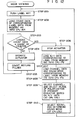
- a satellite broadcasting receiving system for receiving broadcasting waves from a plurality of satellites with a plurality of channels arranged on a geostationary satellite orbit for broadcasting viewing purposes, the receiving system comprising: an antenna for receiving the waves; means for adjusting the antenna direction so as to receive a specific satellite; means for reproducing a signal of a specific channel from the specific satellite as received by the antenna; memory means storing the position data of a satellite corresponding to the specific direction of the antenna and channel select data corresponding to the reproduced signal; operating means for selecting the directioning of the antenna and the channel, requesting the storage of the position of a specific satellite and the channel select data to the memory means, and requesting the viewing of the channel of the stored specific satellite; and control means for controlling the antenna direction adjusting means and the reproducing means according to the selection of the antenna direction and the channel as given by the operating means, storing the data on the position of the specific satellite and the data on channel selection into the memory means according to the request of such data storage by the operating means, and reading
- F ig. 1 illustrates an overall arrangement of a satellite broadcasting receiving system according to an embodiment of the present invention.
- Parabolic antenna 102 directly receives TV waves radiated by an artificial satellite toward the earth.
- Antenna 102 includes reflecting plate 104 with a parabolic surface and primary radiator 108 which is disposed in front of the parabolic antenna and supported and held by holding member 106.
- Antenna 102 is rotatably mounted to post 110 and rotatable in the directions of both azimuth and elevation.
- the direction of the antenna must be adjusted in both the azimuth and elevation directions. Practically, however, a satisfactory reception of the TV waves can be obtained by merely adjusting the antenna direction along the orbit in a predetermined direction.
- the antenna angle can be adjusted by means of actuator 112 with an extensible actuating rod, which is located between post 110 and the lower side of parabolic antenna 102.
- ODU outdoor unit
- IDU indoor unit
- the satellite broadcasting receiving system is comprised of ODU 114 and IDU 118.
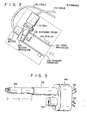
- primary radiator 108 and ODU 114 are as illustrated in Fig. 2, for example.
- primary radiator 108 is comprised of first waveguide 122, scaler 124, antenna probe 126, second waveguide 128, and servomotor 130.
- First waveguide 122 guides the wave reflected by reflecting plate 104 into the antenna probe 126.
- Scaler 124 for improving the efficiency of wave reception is provided around waveguide 122 while being located closer to the inlet of the waveguide.
- Antenna probe 126 passes through the end wall of waveguide 122 and crosses second waveguide 128, and is coupled with servomotor 130.
- Second waveguide 128 guides the electrical signal from probe 126 in the form of electric wave.
- Servomotor 130 rotates antenna probe 126 crossing second waveguide 128 to be ready for receiving the vertically or horizontally polarized wave.
- This motor 130 is controlled by IDU 118 through cable 132.
- ODU 114 is comprised of a waveguide section connecting to second waveguide 128 and a microwave circuit containing the high frequency amplifier and the first frequency converter. The microwave circuit amplifies and frequency converts the microwave signal from the waveguide section. The signal from the microwave circuit is supplied through cable 116 to ID U 118.
- I D U 118 is comprised of signal processing section 120, antenna control section 134, operator section 136, and receiving polarization control section 138.
- the antenna control section 134 sends a control signal through cable 140 to actuator 112, and detects an extension of the actuator rod of actuator 112, viz. an inclination of parabolic antenna 102.
- Operator section 136 has a control panel with a number of controls for manual operation, as will be described later.
- Receiving polarization control section 138 is connected through cable 132 to primary radiator 108.
- Signal processing section 120 processes the received signal as will be described later.
- the video and audio signals are supplied to display unit 142 connected to IDU 118, and the satellite TV signal is visually and aurally reproduced by the display unit.
- Fig. 3 shows an appearance of actuator 112 used in the system shown in Fig. 1.
- Actuator 112 is comprised of DC motor 144, extensible rod 146, and base holder 148.
- DC motor 144 is a reversible motor which can rotate in the forward or reverse direction according to the polarity of the applied voltage. Motor 144 drives actuator rod 146 to control its extension. Base 148 fixedly holds rod 146 and motor 144.
- DC voltage applied to motor 144 is supplied from antenna control section 134 of IDU 118, by motor drive line 150. The number of rotating of DC motor 144 is led in the form of pulses to control section 134 by means of pulse sensing line 152.
- Motor drive line 150 and pulse sensing line 152 are gathered in cable 140 in Fig. 1.
- Conversion of the number of rotating of motor into the number of pulses is performed by the combination of a magnet mounted to the rotating shaft of motor 144 and a HALL sensor mounted to base 148.
- an extension i.e. a length L
- the length L of rod 146 i.e. the inclination of antenna 102, is electrically recognized in terms of an accumulated value of pulses led by sensing line 152.
- F ig. 4 shows a circuit arrangement of IDU 118.
- Antenna control section 134 includes DC power supply 154 for producing a DC voltage applied to motor 144 of actuator 112. The polarity of the DC voltage applied to DC motor 144 through motor drive line 150 is selected by relay 156. The number of pulses representing the number of rotating of motor, which comes from motor 144 through pulse sensing line 152 is counted by up-down counter 158. Count of up-down counter 158 is stored into non-volatile memory 160 in a storing mode to be given later. The count of counter 158 is displayed by LED 162.
- CPU 164 for antenna control is provided for controlling actuation of relay 156, the counting direction of counter 158, and storing operation of the counted value by counter 158 into memory 160, display by LED 162, and the like.
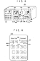
- the operator section 136 of IDU 118 includes label input part 166 having a memory key (M) and ten keys.
- Label input part 166 is for inputting a desired label (any of numerals 0 to 9) in a storing mode, and a label number representative of a desired channel in a viewing mode.
- Operator section 136 contains direction controlling part 168 for giving the direction of antenna 102, and channel controlling part 170 for designating a desired channel to be given later.
- the signal from ODU 114 is supplied to frequency converting circuit 172 for converting the frequency of the signal into a second intermediate frequency.
- Circuit 172 is also supplied with a local oscillating signal from local oscillator 174.
- Local oscillator 174 is controlled by CPU 176 according to the designated channel signal derived from channel controlling part 170 of operator section 136.
- the channel signal from channel controlling part 170 is stored into memory 178 and displayed by LED 180, under control by CPU 176.
- the intermediate frequency signal output from frequency converting circuit 172 is amplified by intermediate frequency (IF) amplifier 182.
- An automatic gain control (AGC) voltage in IF amplifier 182 is applied to signal meter 184 where it is indicated as a strength of receiving signal.
- the signal amplified by amplifier 182 is demodulated by FM demodulator 186.
- the demodulated signal is applied to video processing circuit 188 and sound processing circuit 190 which in turn are produced in the form of reproduced video and sound signals. These signals are visually and aurally reproduced by display unit 142 including an audio system.
- Fig. 5 shows a detailed arrangement of sound processing circuit 190.
- the base-band signal transmitted by the satellite usually contains the aural signals of two channels (channels A and B) in the frequency range 5 MH z to 8 MHz, which are attached to the visual carrier.
- the signal from FM demodulator 186 is passed through band-pass filter (BPF) 192, and input to two sound tuners 194 and 196 for selecting channels A and B .
- BPF band-pass filter
- These tuners 194 and 196 are respectively coupled with local oscillators 198 and 200. These oscillators are controlled by CPU 176 according to the directions by channel control part 170 in operator section 136.
- the signals as selected by tuners 194 and 196 are respectively demodulated by 202 and 204, and applied to matrix 206 which is controlled by CPU 176. Upon receipt of these signals, matrix 206 produces L and R signals.
- the signals of the channels A and B take one of the following three modes.
- channel control part 170 of operation section includes a change between monaural and stereo ((i) and (ii)) and a change between stereo and matrix stereo ((ii) and (iii)).
- Receiving polarization control section 138 sends a control signal to motor 130 for rotating antenna probe 126 of primary radiator 108, in response to the directions from direction controlling part 168. By this control signal, a receiving mode of parabolic antenna 102 is changed.
- FIG. 6 there is shown a front layout of IDU 118. As shown, LED 162 for display the number of pulses is disposed just above direction controlling part 168. Similarly, LED 180 for channel display is located just above channel controlling part 170. Label input part 166 and signal meter 184 are also disposed in a similar layout.
- a viewer pushes up-key 208 or down-key 210 in the direction control part 168 of operator section 136, to change the inclination of parabolic antenna 102.
- antenna control section 134 sets the contacts of relay 156 to the positions shown in Fig. 4, and holds this contact positions.
- the output voltage of DC power supply 154 supplies to DC motor 144 a voltage with a polarity causing the forward rotation of the motor.
- rod 146 rotates in the direction of arrow in Fig. 3, and the length "L" of the actuator rod is extended.
- parabolic antenna 102 is incrementally inclined.
- a train of pulses representing the number of rotating of DC motor 144 are supplied to up-down counter 158, through pulse sensing line 152.
- CPU 164 informs up-down counter 158 that up-key 208 of the direction controlling part 168 has been pushed. Accordingly, at this time, counter 158 counts the number of pulses in the up direction.
- the count of counter 158 is displayed by LED 162 for display the number of pulses under control of CPU 164.
- Channel controlling part 170 is provided with up- and down-keys 212 and 214.
- the up-key 212 When the up-key 212 is pushed by a viewer, the channel number displayed by LED 180 is successively increased from "l". At this time, the channel number is sent from CPU 176 to local oscillator 174, too. Oscillator 174 sends a signal of a frequency representing the channel number is supplied to frequency converting circuit 172, so that the receiving system is ready for receiving the program of the corresponding channel transmitted from the satellite. If up-key 212 is continuously pushed, the displayed channel number of LED 180 is successively increased and the oscillating frequency of local oscillator 174 correspondingly changes.
- the satellite broadcasting receiving system has two operation modes, a storing mode for storing a specific channel transmitted from a broadcasting satellite and a viewing mode for reading and viewing the stored channel.
- a normal or reverse satellite is selected by operating a normal/inverse select key (not shown) in operator section 136.
- the up-key 208 or down-key 210) in direction controlling part 168 is continuously pushed (step 701).
- actuator 112 is operated (step 702) to increase (or decrease) the inclination of antenna 102.
- a count of up-down counter 158 increases (decreases), so that a numerical value displayed by LED 162 for display the number of pulses increases (or decreases) (step 703).
- signal meter 184 may greatly swing its pointer.
- step 704 pushing of up-key 184 (or down-key 210) is stopped (step 704), to stop actuator 112 (step 705).
- the down-key 210 (or up-key 208) is pushed to move the pointer at that point.
- the up- 212 or the down-key 214 of channel controlling part 210 is pushed to select a channel to be stored (step 706).
- the up- and down-keys 216 for sound channel selection in channel control part 170 are operated, and sound mode select keys 218 are operated for selecting a sound mode (step 707).
- the memory key (M) in label input part 166 shown in Fig. 6 is pushed, and then a desired label key (for example, "1") of these 0 to 9 is selected and pushed (step 708).
- a desired label key for example, "1" of these 0 to 9 is selected and pushed (step 708).
- the motor speed as is now displayed by LED 162 and the data of normal/inverse are stored into nonvolatile memory 160, while being attached with label "1" (step 709).
- the channel number as is now displayed by LED 180 for channel display, and the data on the sound channel selection and the sound mode as well are stored into nonvolatile memory 178, while being attached with label "1" (step 710). In this way, a sequence of the storing mode operations are completed.
- another channel may of course be stored.
- the keys in the direction controlling part 168 are operated, and the up-key 212 or the down-key 214 in channel controlling part 170 is pushed to select the desired channel.
- the memory key (M) in label input part 166 is pushed, and a desired label key, for example, a "2" key, is pushed.
- the number of rotating of the motor as is now displayed by LED 162 (equal to that attached with label "I"), and the data on the normal/inverse are stored into memory 160, with label "2" attached thereto.
- the channel number as displayed by LED 180 at that time and the data on the sound selection as well as the sound mode are stored into memory 178, with label "2" attached thereto.
- the target satellite For storing a channel transmitted by another satellite, as in the previous case, the target satellite is selected, the normal/inverse mode is set up, a desired channel is selected, and the sound and the sound mode are selected, and the memory key (M) of label input part 166 and another desired label key, for example, a "3" key, are pushed.
- M memory key
- the fact that the label number is set in counter 158 indicates that antenna 102 is directed in the direction as required. Further, the data on the normal/inverse is read out of memory 160, and supplied to receiving polarization control section 138. By this section 138, the servomotor 130 for rotating antenna probe 126 of primary radiator 108 is controlled using the data of normal/inverse.
- label key for example, "3"
- label input part 166 When the label key (for example, "3") in label input part 166 is pushed, this is sent to CPU 176 for channel tuning by way of CPU 164 for antenna control.
- CP U 176 reads out of memory 178 the channel number with the label number (e.g. "3"), and displays it by LED 180, and controls local oscillator 174 so that its frequency is equal to that for the channel.
- sound processing circuit 190 is controlled by the data on the sound selection and the sound mode as read out from memory 178. In this way, the viewer can view the desired program displayed by display unit 142.
- operator section 136 is integral with IDU 118, as shown in Figs. 4 and 6. However, it may be provided separately from IDU, as shown in Fig. 8. In this case, a transmitter for the direction signals from operator section 136 by infrared rays is installed in remote control set 220.
- IDU 118 contains a receiver for receiving the signals from the transmitter.
- Remote control set 220 may fixedly be set on the front panel of IDU 118, if necessary. Use of such a remote control set enables the viewer to make an easy operation in the storing mode and the viewing mode.
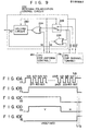
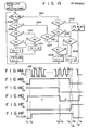
- the receiving polarization control circuit 222 of the receiving polarization control section 138 as shown in Fig. 4 is constructed with two exclusive OR circuits 224 and 226, select switch 228 and holding circuit 230 as shown in Fig. 9. Supplied to control circuit 222 are the following three control signals from CPU 176 for channel tuning.
- the control signal is a channel select signal CS with "high" for odd channels and "low” for even channels, as shown in Fig. 10A.
- the first control signal indicates that CPU 176 is so selected as to successively receive 1 to 24 channels.
- the second control signal is a frequency scanning signal FS indicating that the frequency scanning for channel detection is performed, as shown in Fig. 10B.
- the third control signal is a select control signal SS for selecting a receiving state of antenna, for example, vertically or horizontally polarized wave. This signal changes its state, for example, from “high” to "low” before the second scanning is performed following the first scanning for all of the channels 1 to 24.
- the channel select signal CS and the select control signal SS are input to select switch 228.
- the output signal of this switch 228 is input to the first input terminal of exclusive OR circuit 224.
- Input to the second input terminal of circuit 224 is a signal NI representing the type of satellite, which is derived from CPU 164 for antenna control.
- the output signal from circuit 224 is input to holding circuit 230.
- the frequency scanning signal FS is supplied to holding circuit 230 and CPU 164 for antenna control, and further to select switch 228 for its switch control.
- the receiving polarization control signal HV as the output signal of holding circuit 230 as shown in Fig. 10D and the channel select signal CS are input to exclusive OR circuit 226.
- the type of satellite is checked, and the result of the check is supplied as satellite type signal NI to CPU 164.
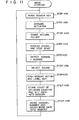
- Fig. 11 Search key 232, which is contained in the channel controlling part 170 of operator section 1 36, is pushed for searching a desired satellite (step 1101). Responsive to the pushing of search key 232, CP U 176 for channel tuning directs CPU 164 for antenna control to change the direction of parabolic antenna 176 in fine steps. CPU 164 applies DC voltage of DC power supply 154 to DC motor 144 in actuator 112, to change the direction of parabolic antenna 102 (step 1102).
- the direction of antenna 102 is recognized by a count of up-down counter 158 (step 1103).
- CP U 176 sends a control signal to local oscillator 174, and then oscillator 174 supplies local oscillating signals necessary for successive reception of channels 1 to 24 from the satellite to frequency converting circuit 172.
- Display unit 142 reproduces channels 1 to 24 in successive manner through frequency converting circuit 172, IF amplifier 182, FM demodulator 186, video processing circuit 188, and sound processing circuit 190. If antenna 102 is not directed to the target satellite, none of the channels are not reproduced.
- receiving polarization control signal H V takes a “low” state representing that the receiver is conditioned for horizontally polarized wave "H".
- a signal representing the vertically polarized wave " V " is sent to motor 130 by way of cable 132.
- antenna probe 126 is rotated, so that antenna 102 is ready for receiving the vertically polarized wave.
- C P U 176 for channel tuning makes "low” in signal state the frequency scanning signal FS to be sent to receiving polarization control circuit 222, as shown in F ig. 10B, and stops the channel select scanning (step 1104).
- channel select signal CS keeps a "high” state representing that the stopped channel belongs to the odd channel.
- receiving polarization control signal HV is in "low” state representing that the receiver is ready for the horizontally polarized wave, "H”. Therefore, the output of exclusive OR circuit 226 receiving these signals goes “high”. Therefore, supplied to exclusive OR circuit 226 is satellite type signal N I of "high” indicating that the satellite to which the antenna is directed is of the inverse type. In this way, the type of satellite is recognized (step 1105).
- the result of satellite type recognition is indicated by LED, for example.
- odd and even channels are respectively represented by “high” and “low” states of channel select signal CS.
- the vertically and horizontally polarized waves of receiving waves are represented by “high” and “low” states of receiving polarization signal HV.
- Signal NI for satellite type is sent to CPU 164 for antenna control and again input to exclusive OR circuit 224. That is, since the output of circuit 224 is "high", a "high” signal as the signal NI is input to exclusive OR circuit 224.
- Select switch 228 is turned to the lower position in Fig. 9.
- the first input signal to circuit 224 serves as channel select signal CS, and the output signal of circuit 224 goes “low".
- this "low” signal time t2
- holding circuit 230 continuously produces a "low” signal as receiving polarization control signal HV.
- receiving polarization control circuit 222 continues the control of motor 130 so that antenna 102 can receive the horizontally polarized wave "H".
- a viewer desires to store this channel 7, following the sound channel selection and the sound mode (step 1106), the viewer pushes the memory key (M) and a desired label key of those 1 to 9, for example, the key with label number 3 (step 1107), as in the above-mentioned embodiment.
- a count (for example, 65) of up-down counter 158 corresponding to the direction of antenna 102 and the signal NI (of "high") indicating that the satellite is an inverse satellite are stored into nonvolatile memory 160, with label number 3 attached thereto (step 1108).
- the channel number (07) at that time, and the data on the sound selection and mode selection are stored into memory 178, with label number 3 attached thereto (step 1109).
- channel controlling part 170 If the viewer does not desire to store channel 7, he inputs it from channel controlling part 170, that is, pushes search key 232 of channel controlling part 170 to again scan channels 8 to 24. At this time, if a desired channel for storage is not found, he pushes the memory key ( M ) in label input part 166, and performs the operations as mentioned above. If the desired channel is not transmitted by the specific satellite, search key 232 in channel controlling part 170-is again pushed, antenna 102 direction is minutely changed and the receiving frequency scanning for channel selection is executed. In this way, storing operation of the desired channel is performed.
- the viewing mode will be described referring to Fig. 12. If the viewer desires to view the channel labeled as 3, he keys in 3 from label input part 166 (step 1201). Then, CPU 164 for antenna control reads out the count (65) attached with label number 3 from memory 160 (step 1202), and controls actuator 112 so that the count of up-down counter 158 reaches this value (steps 1203 to 1206). In this way, antenna 102 is directed toward a specific satellite.
- CPU 164 reads out from memory 160 a state that this satellite is an inverse satellite, and supplies signal NI to receiving polarization control circuit 222.
- CP U 176 for channel tuning reads out from memory 178 the contents of label number 3, viz. "07” and the data on the sound channel selection and the sound mode (step 1208).
- CPU 176 for channel tuning controls local oscillator 174 so as to receive the channel 7, and supplies channel select signal to receiving polarization control circuit 222.
- receiving polarization control circuit 222 sends receiving polarization control signal HV of "low” to motor 130, and antenna 102 is ready for receiving the horizontally polarized wave "H" (step 1209).
- CP U 176 performs the sound channel selection, and selects a sound mode (step 1210). Through the sequence of the above operations, the receiver is ready for receiving the channel 7 from the inverse satellite.
- LED 162 for display the number of pulses is used for indicating the count of up-down counter 158 corresponding to the direction of the antenna 102. If necessary, input label number, e.g. 3, may be displayed by this LED.
- the above embodiment employs the special circuit as receiving polarization control circuit.
- the satellite type recognition may be executed by CPU 164 for antenna control. This recognition by CPU will be given referring to a flowchart of Fig. 13, and timing waveforms of Figs. 14A to 14F.
- channel select signal CS goes "high", as shown in Fig. 14A, so that receiving polarization control signal HV goes “high”, as shown in Fig. 14D.
- frequency scanning signal FS goes "high” as shown in F ig. 14 B .
- the receiving frequencies are scanned while the direction of the antenna is gradually changed.
- FS flag is "low”, as shown in Fig. 14F, the FS flag goes "high” through steps 1301 and 1302, as shown in Fig. 14F. Since frequency scanning signal FS has been "high”, select control signal S S is checked through steps 1303 and 1304 in Fig. 13. As shown in Fig.
- select control signal SS is "high” till time t 13 , and satellite type signal NI is “low” till that time, as shown in Fig. 14E. Accordingly, receiving polarization control signal HV keeps the “high” state till this time point, as shown in Fig. 14D, through steps 1305 and 1306 in Fig. 13. At time t l4r select control signal SS goes “low” as shown in Fig. 14C. As a result, receiving polarization control signal HV goes "low”, as shown in Fig. 14D, through steps 1307 and 1308 in Fig. 13.
- the FS flag goes "low” as shown in Fig. 14F.
- the satellite is recognized as an inverse satellite.
- receiving polarization control signal HV is determined accdrding to channel select signal CS and satellite type signal N I.
- the receiving polarization control circuit of Fig. 9 may be replaced by a circuit 234 of Fig. 15.
- polarization control signal DS is used in place of select control signal SS.
- the polarization control signal DS and channel select signal CS are input to exclusive OR circuit 236 for recognizing the type of satellite.
- the output signal of circuit 236 is sent, as satellite type signal NI, to CPU 164 for antenna control.
- the signal NI and channel select signal CS as output from CPU 164 for antenna control are input to another exclusive OR circuit 238.
- the output signal of circuit 238 is input to the first input terminal of select switch 240.
- Polarization control signal DS is-input to the second input terminal of switch 240.
- the frequency scanning signal FS output from CPU 176 for channel tuning is supplied to CPU 164 for channel control, and switch 240 is controlled by the output signal from delay 242.
- frequency scanning signal FS goes "high” as shown in Fig. 16B, and the scanning of receiving frequencies starts.
- switch 240 is turned to the lower side as shown in Fig. 15.
- signal FS goes "high”
- polarization control signal DS is output to antenna 102, in the form of the output signal of receiving polarization control circuit 234.
- the satellite type signal N1 supplied from CPU 164 to exclusive OR circuit 238 keeps an undefined state, i.e. "high” or “low” state.
- the signal NI is produced as the output signal from exclusive OR circuit 236, this value is transferred to exclusive OR circuit 238.
- select switch 240 is again turned to the lower side.
- an appropriate polarization has been determined using channel select signal CS and satellite type signal NI.
- the "low” signal is transferred as the receiving polarization control signal to antenna 102.
- signal NI together with the count corresponding to the satellite direction, is stored into memory 160, with a predetermined label number attached thereto.
- a desired channel is also stored into memory 178, with the equal label number attached thereto. In the viewing mode, the label number is designated and the desired channel is reproduced.
- two memories are used for storing the count corresponding to the antenna direction and the satellite type signal NI, and a desired channel, respectively. It is evident that these pieces of data may be stored l into a single memory, with a specific label attached thereto. Further, the type of the memory is not limited to nonvolatile type.
- the amplitude of the output signal of IF amplifier 182 is used for detecting presence or not of satellite broadcasting. Alternatively, this can be detected by detection of a sync signal from a sync separation circuit (not shown) of video processing circuit 188.
- the TV signal of each channel contains both the visual and aural signals, it may contain only aural signal.
- a speaker system is used in place of the display unit.
- label numbers may be substituted by alphabetic letters, such as A, B, C, etc., or by the combination of alphabetic letters and numbers, such as A1, F3, G4, etc..
- nonvolatile memories are used for data storing, data is not volatilized if power supply is turned off, and after power on, it may be set in the viewing mode.
Abstract
Description
- This invention relates to a satellite broadcasting receiving system in which for viewing a desired program, viewers on ground directly receive, by parabolic antennas, the television waves radiated from an artificial satellite toward the earth.
- In recent days, a satellite broadcasting receiving system has developed and put into practical use in many countries in the world. In this system, an artificial satellite radiates television waves toward the earth, while viewers on the ground receive the waves by parabolic antennas. Generally, in this system, a plurality of the artificial satellites for broadcasting are in such a geostationary satellite orbit that the viewers can receive the radiated television waves. To receive the waves from all of the satellites, the viewer must direct the antenna toward the satellite. One satellite station has normally a plurality of channels. (For example, 24 channels in U.S.A.) In this broadcasting system, for receiving a desired channel, the viewer first directs the antenna toward the satellite which is radiating the waves containing such a channel, and selects the desired channel from those of the received waves.
- Thus, for viewing a desired television program in the satellite broadcasting receiving system, the viewer must take two steps for reception, directing of the antenna and selecting of the desired channel. The directing operation of antenna is done mechanically, while the channel selection is achieved by an electrical process. For this reason, two mechanical and electrical systems are separately provided in the television set.
- Two steps for channel selection require much time and labor.
- To avoid interference among the channels, the channels are classified into two groups, odd numbered group and even numbered group. The waves of these groups of channels are radiated with different polarizations. In a normal satellite, the horizontally and vertically polarized electromagnetic waves are used for transmitting the even and odd numbered groups of channels, respectively. In an inverse satellite, the even numbered channels are transmitted by the vertical polarization, and the odd numbered channels by the horizontal polarization. When the adjacent satellites are closely put on the orbit, the normal and inverse satellites are alternately put on the orbit. In this respect, the viewer must recognize the type of the satellite for his channel selection. Specifically, in selecting a desired channel, the viewer recognizes a type of the satellite radiating the desired channel wave, and decides if the channel group containing the desired channel is even or odd numbered one. Finally, he sets the plane of the polarization of the waves input to the converter of the antenna, to the horizontally polarized wave (H) or the vertically polarized wave (V). That is, he operates a normal/inverse switch for such selection.
- There is a case that the satellite does not use some channels for its TV wave transmission. In such a case, if the TV program of the channel as selected by the viewer is not broadcasted, he must check if the TV broadcasting through the selected channel is not performed or the selection by the normal/reverse switch is wrong. This check makes the channel selection further complicated.
- The base-band signal transmitted by the satellite usually contains the aural signals of two channels (channels A and B) in the
frequency range 5 MHz to 8 MHz, which are attached to the visual signal. The signals of the channels A and B take one of the following three modes. - i) Monaural mode; Audio signals are independently carried on these channels A and B.
- ii) Independent stereo mode; L and R signals of stereo are carried on the these channels.
- iii) Matrix stereo mode; L+R and L-R signals of stereo are carried on these channels.
- The types of these modes and the frequencies of the channels A and B depend on satellites and channel numbers. Therefore, every time the satellite and the channel are changed to other ones, the viewer must reset these items.
- As described above, for selecting a desired program in the satellite broadcasting system, the viewer directs the antenna toward a specific satellite, selects a channel carrying the desired program, operates the normal/ inverse switch, and finally the sound mode. The channel selecting operation of many steps is troublesome and inconvenient for viewers.
- The present invention is contrived in consideration of these circumstances, and is aimed to provide a satellite broadcasting receiving system which can concurrently adjust the directing of antenna and the selection of a desired channel in a simple manner.
- The present invention is further aimed to provide a satellite broadcasting receiving system which can automatically check if the target satellite is of the normal type or the inverse type, and enables the viewer to view a desired program without knowledge of the types of the satellites.
- To achieve the above objects, there is provided a satellite broadcasting receiving system for receiving broadcasting waves from a plurality of satellites with a plurality of channels arranged on a geostationary satellite orbit for broadcasting viewing purposes, the receiving system comprising: an antenna for receiving the waves; means for adjusting the antenna direction so as to receive a specific satellite; means for reproducing a signal of a specific channel from the specific satellite as received by the antenna; memory means storing the position data of a satellite corresponding to the specific direction of the antenna and channel select data corresponding to the reproduced signal; operating means for selecting the directioning of the antenna and the channel, requesting the storage of the position of a specific satellite and the channel select data to the memory means, and requesting the viewing of the channel of the stored specific satellite; and control means for controlling the antenna direction adjusting means and the reproducing means according to the selection of the antenna direction and the channel as given by the operating means, storing the data on the position of the specific satellite and the data on channel selection into the memory means according to the request of such data storage by the operating means, and reading out of the memory means the stored data on the specific satellite position and channel selection data according to the specific satellite channel viewing request by the operating means, and controlling the antenna direction adjusting means and the reproducing means.
- This invention can be more fuly understood from the following detailed description when taken in conjunction with the accompanying drawings, in which:
- Fig. 1 shows a diagram illustrating an overall system of a satellite broadcasting receiving system according to an embodiment of the present invention;
- Fig. 2 shows a side view of a primary radiator and outdoor unit (ODU) used in the system shown in Fig. 1, the view being partially illustrated in cross sectional form;
- Fig. 3 shows a perspective view of an actuator used in the system shown in Fig. 1;
- Fig. 4 is a block diagram of a detailed circuit arrangement of the indoor unit (IDU);
- Fig. 5 is a block diagram of a detailed circuit arrangement of a sound processing circuit of IDU;
- Fig. 6 is a perspective view illustrating an outer appearance of IDU;
- Fig. 7 shows a flowchart useful in explaining the storing operation mode of the satellite broadcasting receiving system shown in Fig. 1;
- Fig. 8 shows a front view illustrating a front layout of a remote controller main frame used for an operator section of IDU;
- Fig. 9 shows a circuit diagram of a detailed arrangement of a receiving polarization control circuit forming a receiving polarization control section of IDU;
- Figs. 10A to 10E show a timing chart useful in explaining the operation of the circuit of Fig. 9;
- Fig. 11 shows a flowchart for explaining the storing operation mode of the satellite broadcasting receiving system using the Fig. 9 circuit;
- Fig. 12 shows a flowchart for explaining the viewing mode of the satellite broadcasting system using the Fig. 9 circuit;
- Fig. 13 shows a flowchart illustrating a control flow when the function of the Fig. 9 circuit is implemented by CPU for antenna control;
- Figs. 14A to 14F show a timing chart useful in explaining the control flow as illustrated by the flow chart of Fig. 13;
- Fig. 15 is a circuit diagram of another arrangement of the receiving polarization control circuit; and
- Figs. 16A to 16E show a timing chart for explaining the operation of the Fig. 15 circuit.
- One embodiment of the present invention will now be described in detail with reference to the accompanying drawings.
- Fig. 1 illustrates an overall arrangement of a satellite broadcasting receiving system according to an embodiment of the present invention.
Parabolic antenna 102 directly receives TV waves radiated by an artificial satellite toward the earth.Antenna 102 includes reflectingplate 104 with a parabolic surface andprimary radiator 108 which is disposed in front of the parabolic antenna and supported and held by holdingmember 106.Antenna 102 is rotatably mounted topost 110 and rotatable in the directions of both azimuth and elevation. - To accurately direct
antenna 102 toward a satellite circulating on a geostationary orbit, strictly, the direction of the antenna must be adjusted in both the azimuth and elevation directions. Practically, however, a satisfactory reception of the TV waves can be obtained by merely adjusting the antenna direction along the orbit in a predetermined direction. The antenna angle can be adjusted by means ofactuator 112 with an extensible actuating rod, which is located betweenpost 110 and the lower side ofparabolic antenna 102. - TV wave received by
primary radiator 108 enter outdoor unit (ODU) 114 as connected to the radiator. InODU 114, the wave pass through a high frequency amplifier and a first frequency converter. The amplified and frequency converted TV signal is guided bycable 116 to thesignal processing unit 120 in indoor unit (IDU) 118. The satellite broadcasting receiving system is comprised ofODU 114 andIDU 118. - The structures of
primary radiator 108 andODU 114 are as illustrated in Fig. 2, for example. As shown,primary radiator 108 is comprised offirst waveguide 122,scaler 124,antenna probe 126,second waveguide 128, andservomotor 130.First waveguide 122 guides the wave reflected by reflectingplate 104 into theantenna probe 126.Scaler 124 for improving the efficiency of wave reception is provided aroundwaveguide 122 while being located closer to the inlet of the waveguide.Antenna probe 126 passes through the end wall ofwaveguide 122 and crossessecond waveguide 128, and is coupled withservomotor 130.Second waveguide 128 guides the electrical signal fromprobe 126 in the form of electric wave.Servomotor 130 rotatesantenna probe 126 crossingsecond waveguide 128 to be ready for receiving the vertically or horizontally polarized wave. Thismotor 130 is controlled byIDU 118 throughcable 132.ODU 114 is comprised of a waveguide section connecting tosecond waveguide 128 and a microwave circuit containing the high frequency amplifier and the first frequency converter. The microwave circuit amplifies and frequency converts the microwave signal from the waveguide section. The signal from the microwave circuit is supplied throughcable 116 toID U 118. - I
D U 118, as shown in Fig. 1, is comprised ofsignal processing section 120,antenna control section 134,operator section 136, and receivingpolarization control section 138. Theantenna control section 134 sends a control signal throughcable 140 toactuator 112, and detects an extension of the actuator rod ofactuator 112, viz. an inclination ofparabolic antenna 102.Operator section 136 has a control panel with a number of controls for manual operation, as will be described later. Receivingpolarization control section 138 is connected throughcable 132 toprimary radiator 108. -
Signal processing section 120 processes the received signal as will be described later. The video and audio signals are supplied to displayunit 142 connected toIDU 118, and the satellite TV signal is visually and aurally reproduced by the display unit. - Fig. 3 shows an appearance of
actuator 112 used in the system shown in Fig. 1.Actuator 112 is comprised ofDC motor 144,extensible rod 146, andbase holder 148.DC motor 144 is a reversible motor which can rotate in the forward or reverse direction according to the polarity of the applied voltage.Motor 144 drivesactuator rod 146 to control its extension.Base 148 fixedly holdsrod 146 andmotor 144. DC voltage applied tomotor 144 is supplied fromantenna control section 134 ofIDU 118, bymotor drive line 150. The number of rotating ofDC motor 144 is led in the form of pulses to controlsection 134 by means ofpulse sensing line 152.Motor drive line 150 andpulse sensing line 152 are gathered incable 140 in Fig. 1. Conversion of the number of rotating of motor into the number of pulses is performed by the combination of a magnet mounted to the rotating shaft ofmotor 144 and a HALL sensor mounted tobase 148. According to the direction and the number of rotation ofmotor 144, an extension, i.e. a length L, ofrod 146 changes, so that an inclination ofparabolic antenna 102 changes. The length L ofrod 146, i.e. the inclination ofantenna 102, is electrically recognized in terms of an accumulated value of pulses led by sensingline 152. - Fig. 4 shows a circuit arrangement of
IDU 118.Antenna control section 134 includesDC power supply 154 for producing a DC voltage applied tomotor 144 ofactuator 112. The polarity of the DC voltage applied toDC motor 144 throughmotor drive line 150 is selected byrelay 156. The number of pulses representing the number of rotating of motor, which comes frommotor 144 throughpulse sensing line 152 is counted by up-down counter 158. Count of up-down counter 158 is stored intonon-volatile memory 160 in a storing mode to be given later. The count ofcounter 158 is displayed byLED 162.CPU 164 for antenna control is provided for controlling actuation ofrelay 156, the counting direction ofcounter 158, and storing operation of the counted value bycounter 158 intomemory 160, display byLED 162, and the like. - The
operator section 136 ofIDU 118 includeslabel input part 166 having a memory key (M) and ten keys.Label input part 166 is for inputting a desired label (any of numerals 0 to 9) in a storing mode, and a label number representative of a desired channel in a viewing mode.Operator section 136 containsdirection controlling part 168 for giving the direction ofantenna 102, andchannel controlling part 170 for designating a desired channel to be given later. - In the
signal processing section 120 ofIDU 118, the signal fromODU 114 is supplied tofrequency converting circuit 172 for converting the frequency of the signal into a second intermediate frequency.Circuit 172 is also supplied with a local oscillating signal fromlocal oscillator 174.Local oscillator 174 is controlled byCPU 176 according to the designated channel signal derived fromchannel controlling part 170 ofoperator section 136. The channel signal fromchannel controlling part 170 is stored intomemory 178 and displayed byLED 180, under control byCPU 176. - The intermediate frequency signal output from
frequency converting circuit 172 is amplified by intermediate frequency (IF)amplifier 182. An automatic gain control (AGC) voltage inIF amplifier 182 is applied to signalmeter 184 where it is indicated as a strength of receiving signal. The signal amplified byamplifier 182 is demodulated byFM demodulator 186. The demodulated signal is applied tovideo processing circuit 188 andsound processing circuit 190 which in turn are produced in the form of reproduced video and sound signals. These signals are visually and aurally reproduced bydisplay unit 142 including an audio system. - Fig. 5 shows a detailed arrangement of
sound processing circuit 190. The base-band signal transmitted by the satellite usually contains the aural signals of two channels (channels A and B) in the frequency range 5 MHz to 8 MHz, which are attached to the visual carrier. Accordingly, the signal fromFM demodulator 186 is passed through band-pass filter (BPF) 192, and input to twosound tuners tuners local oscillators CPU 176 according to the directions bychannel control part 170 inoperator section 136. The signals as selected bytuners matrix 206 which is controlled byCPU 176. Upon receipt of these signals,matrix 206 produces L and R signals. - As recalled, the signals of the channels A and B take one of the following three modes.
-
- i) Monaural mode; Audio signals are independently carried on these channels A and B.
- ii) Independent stereo mode; L and R signals of stereo are carried on the these channels.
- iii) Matrix stereo mode; L+R and L-R signals of stereo are carried on these channels.
- The directions given by
channel control part 170 of operation section include a change between monaural and stereo ((i) and (ii)) and a change between stereo and matrix stereo ((ii) and (iii)). - Receiving
polarization control section 138 sends a control signal tomotor 130 for rotatingantenna probe 126 ofprimary radiator 108, in response to the directions fromdirection controlling part 168. By this control signal, a receiving mode ofparabolic antenna 102 is changed. - Turning now to Fig. 6, there is shown a front layout of
IDU 118. As shown,LED 162 for display the number of pulses is disposed just abovedirection controlling part 168. Similarly,LED 180 for channel display is located just abovechannel controlling part 170.Label input part 166 andsignal meter 184 are also disposed in a similar layout. - The operation of the satellite broadcasting receiving system thus arranged will be described. Before description of an actual operation, the system operation will be given when the up- and down-keys of
direction control part 168 andchannel controlling part 170 are depressed. - As a first step, a viewer pushes up-
key 208 or down-key 210 in thedirection control part 168 ofoperator section 136, to change the inclination ofparabolic antenna 102. Upon depression of up-key 208,antenna control section 134 sets the contacts ofrelay 156 to the positions shown in Fig. 4, and holds this contact positions. Under this condition, the output voltage ofDC power supply 154 supplies to DC motor 144 a voltage with a polarity causing the forward rotation of the motor. With the forward rotation,rod 146 rotates in the direction of arrow in Fig. 3, and the length "L" of the actuator rod is extended. As a result,parabolic antenna 102 is incrementally inclined. - A train of pulses representing the number of rotating of
DC motor 144 are supplied to up-down counter 158, throughpulse sensing line 152.CPU 164 informs up-down counter 158 that up-key 208 of thedirection controlling part 168 has been pushed. Accordingly, at this time, counter 158 counts the number of pulses in the up direction. The count ofcounter 158 is displayed byLED 162 for display the number of pulses under control ofCPU 164. When up-key 208 ofdirection control part 168 is continuously pushed,antenna 102 increases its inclination. With the inclination increase, the numeral displayed byLED 162 increases. - When down-
key 210 ofdirection control part 168 is continuously pushed, the contacts ofrelay 156 are made in contact with the other positions, so thatmotor 144 is reversely rotated andactuator rod 146 is retracted to shorten its length L. Under this condition, up-down counter 158 counts pulses in the down direction, so that the displayed numeral ofLED 162 is progressively decreased. If neither the up- and down-keys 208 nor 210 is pushed, the contacts of therelay 156 are not set to the contact positions, so thatmotor 144 is at a standstill. Thus, the displayed numerical value ofLED 162 indicates the direction ofparabolic antenna 102, and therefore the position of a target satellite. -
Channel controlling part 170 is provided with up- and down-keys key 212 is pushed by a viewer, the channel number displayed byLED 180 is successively increased from "l". At this time, the channel number is sent fromCPU 176 tolocal oscillator 174, too.Oscillator 174 sends a signal of a frequency representing the channel number is supplied tofrequency converting circuit 172, so that the receiving system is ready for receiving the program of the corresponding channel transmitted from the satellite. If up-key 212 is continuously pushed, the displayed channel number ofLED 180 is successively increased and the oscillating frequency oflocal oscillator 174 correspondingly changes. - The satellite broadcasting receiving system has two operation modes, a storing mode for storing a specific channel transmitted from a broadcasting satellite and a viewing mode for reading and viewing the stored channel.
- The storing mode will be given referring a flowchart shown in Fig. 7. As a first step, a normal or reverse satellite is selected by operating a normal/inverse select key (not shown) in
operator section 136. Then, the up-key 208 (or down-key 210) indirection controlling part 168 is continuously pushed (step 701). Upon the pushing of the key,actuator 112 is operated (step 702) to increase (or decrease) the inclination ofantenna 102. With this increase of the antenna inclination, a count of up-down counter 158 increases (decreases), so that a numerical value displayed byLED 162 for display the number of pulses increases (or decreases) (step 703). During this process, signalmeter 184 may greatly swing its pointer. If the meter pointer is greatly swung, pushing of up-key 184 (or down-key 210) is stopped (step 704), to stop actuator 112 (step 705). When the meter pointer passes the point on the meter scale where the pointer greatly swings, the down-key 210 (or up-key 208) is pushed to move the pointer at that point. Then, the up- 212 or the down-key 214 ofchannel controlling part 210 is pushed to select a channel to be stored (step 706). For selecting a desired sound, the up- and down-keys 216 for sound channel selection inchannel control part 170 are operated, and sound modeselect keys 218 are operated for selecting a sound mode (step 707). Following these steps for the desired channel selection, the sound channel selection and the sound mode selection, the memory key (M) inlabel input part 166 shown in Fig. 6 is pushed, and then a desired label key (for example, "1") of these 0 to 9 is selected and pushed (step 708). Upon depression of the label key, under control ofCPU 176, the motor speed as is now displayed byLED 162 and the data of normal/inverse are stored intononvolatile memory 160, while being attached with label "1" (step 709). Further, the channel number as is now displayed byLED 180 for channel display, and the data on the sound channel selection and the sound mode as well are stored intononvolatile memory 178, while being attached with label "1" (step 710). In this way, a sequence of the storing mode operations are completed. - Succeedingly, another channel may of course be stored. For storing another desired channel of the same satellite, none of the keys in the
direction controlling part 168 are operated, and the up-key 212 or the down-key 214 inchannel controlling part 170 is pushed to select the desired channel. Following the channel selection, the memory key (M) inlabel input part 166 is pushed, and a desired label key, for example, a "2" key, is pushed. Then, the number of rotating of the motor as is now displayed by LED 162 (equal to that attached with label "I"), and the data on the normal/inverse are stored intomemory 160, with label "2" attached thereto. At the same time, the channel number as displayed byLED 180 at that time and the data on the sound selection as well as the sound mode are stored intomemory 178, with label "2" attached thereto. - For storing a channel transmitted by another satellite, as in the previous case, the target satellite is selected, the normal/inverse mode is set up, a desired channel is selected, and the sound and the sound mode are selected, and the memory key (M) of
label input part 166 and another desired label key, for example, a "3" key, are pushed. These pieces of data are stored intomemories - The operation by related controls and the system operation of the satellite broadcasting receiving system will be given. When a viewer desires to view a program of a channel, he pushes the key with the label number (for example, "3") already attached corresponding to the desired channel. Responsive to this key operation,
CPU 164 reads out ofnonvolatile memory 160 the number of pulses representing the number of rotating of the motor as set by that label number, causesLED 162 to display a numeral representing the number of rotating of the motor, and actuatesrelay 156 so that up-down counter 158 counts the number of pulses attached with that label number. The count ofcounter 158 corresponds to an inclination ofparabolic antenna 102, i.e. the length ofactuator rod 146 ofactuator 112. Therefore, the fact that the label number is set incounter 158 indicates thatantenna 102 is directed in the direction as required. Further, the data on the normal/inverse is read out ofmemory 160, and supplied to receivingpolarization control section 138. By thissection 138, theservomotor 130 for rotatingantenna probe 126 ofprimary radiator 108 is controlled using the data of normal/inverse. - When the label key (for example, "3") in
label input part 166 is pushed, this is sent toCPU 176 for channel tuning by way ofCPU 164 for antenna control.CP U 176 reads out ofmemory 178 the channel number with the label number (e.g. "3"), and displays it byLED 180, and controlslocal oscillator 174 so that its frequency is equal to that for the channel. Further,sound processing circuit 190 is controlled by the data on the sound selection and the sound mode as read out frommemory 178. In this way, the viewer can view the desired program displayed bydisplay unit 142. - In the above-mentioned embodiment,
operator section 136 is integral withIDU 118, as shown in Figs. 4 and 6. However, it may be provided separately from IDU, as shown in Fig. 8. In this case, a transmitter for the direction signals fromoperator section 136 by infrared rays is installed in remote control set 220.IDU 118 contains a receiver for receiving the signals from the transmitter. Remote control set 220 may fixedly be set on the front panel ofIDU 118, if necessary. Use of such a remote control set enables the viewer to make an easy operation in the storing mode and the viewing mode. - It is preferable to automatically check if a target satellite is of the normal or inverse type. If so, the target satellite can be selected without any knowledge of the type of satellite. To this end, the receiving
polarization control circuit 222 of the receivingpolarization control section 138 as shown in Fig. 4 is constructed with two exclusive ORcircuits select switch 228 and holdingcircuit 230 as shown in Fig. 9. Supplied to controlcircuit 222 are the following three control signals fromCPU 176 for channel tuning. The control signal is a channel select signal CS with "high" for odd channels and "low" for even channels, as shown in Fig. 10A. Whenchannel controlling part 170 directs the frequency scanning of receiving waves for another channel detection, the first control signal indicates thatCPU 176 is so selected as to successively receive 1 to 24 channels. The second control signal is a frequency scanning signal FS indicating that the frequency scanning for channel detection is performed, as shown in Fig. 10B. The third control signal is a select control signal SS for selecting a receiving state of antenna, for example, vertically or horizontally polarized wave. This signal changes its state, for example, from "high" to "low" before the second scanning is performed following the first scanning for all of thechannels 1 to 24. - The channel select signal CS and the select control signal SS are input to select
switch 228. The output signal of thisswitch 228 is input to the first input terminal of exclusive ORcircuit 224. Input to the second input terminal ofcircuit 224 is a signal NI representing the type of satellite, which is derived fromCPU 164 for antenna control. The output signal fromcircuit 224 is input to holdingcircuit 230. The frequency scanning signal FS is supplied to holdingcircuit 230 andCPU 164 for antenna control, and further to selectswitch 228 for its switch control. The receiving polarization control signal HV as the output signal of holdingcircuit 230 as shown in Fig. 10D and the channel select signal CS are input to exclusive ORcircuit 226. Incircuit 226, the type of satellite is checked, and the result of the check is supplied as satellite type signal NI toCPU 164. - The operation of the satellite broadcasting receiving system with the receiving
polarization control circuit 222, of which the arrangement has been described referring to Figs. 1 and 4, will be described. The storing mode will first be given using a flowchart shown in Fig. 11.Search key 232, which is contained in thechannel controlling part 170 of operator section 136, is pushed for searching a desired satellite (step 1101). Responsive to the pushing ofsearch key 232,CP U 176 for channel tuning directsCPU 164 for antenna control to change the direction ofparabolic antenna 176 in fine steps.CPU 164 applies DC voltage ofDC power supply 154 toDC motor 144 inactuator 112, to change the direction of parabolic antenna 102 (step 1102). The direction ofantenna 102 is recognized by a count of up-down counter 158 (step 1103). Under this condition, CPU 176 sends a control signal tolocal oscillator 174, and then oscillator 174 supplies local oscillating signals necessary for successive reception of channels 1 to 24 from the satellite tofrequency converting circuit 172.Display unit 142 reproduceschannels 1 to 24 in successive manner throughfrequency converting circuit 172, IFamplifier 182, FM demodulator 186,video processing circuit 188, andsound processing circuit 190. Ifantenna 102 is not directed to the target satellite, none of the channels are not reproduced. - When
search key 232 is pushed, and the scanning of receiving frequency for channel selection is performed,CPU 176 for channel tuning sends frequency scanning signal FS to receivingpolarization control circuit 222, so thatswitch 228 is switched from the upper position to the lower position in the drawing. Switch control signal SS, as shown in Fig. 10C, supplied fromCPU 176 is supplied to exclusive ORcircuit 224 throughselect switch 228. The output signal ofcircuit 224 goes through holdingcircuit 230 and serves as receiving polarization control signal HV. Accordingly, when select control signal SS is "high", receiving polarization control signal HV goes "high", as shown in Fig. 10D. This state of signal HV represents that the receiver is conditioned for receiving the vertically polarized wave "V". When select control signal SS is "low", receiving polarization control signal HV takes a "low" state representing that the receiver is conditioned for horizontally polarized wave "H". At the initial stage of the scanning for channel selection, a signal representing the vertically polarized wave "V", as receiving polarization control signal HV, is sent tomotor 130 by way ofcable 132. As a result,antenna probe 126 is rotated, so thatantenna 102 is ready for receiving the vertically polarized wave. - During the scanning for chanpel selection, if the satellite broadcasting is received, the pointer of
signal meter 184 insignal processing section 120 of Fig. 4 swings. The signal at this time is sent toC PU 176 for channel tuning. - There is a case that after
antenna 102 is ready for receiving vertically polarized wave "V", and thechannels 1 to 24 are scanned for its selection, no satellite broadcasting is received. In this case, select signal SS goes "low". Accordingly, the output signal of receivingpolarization control circuit 222 also goes "low", that is,antenna 102 is ready for receiving horizontally polarized wave "H". Under this condition, thechannels 1 to 24 are successively received. If the satellite broadcasting is not yet detected,CPU 176 for channel tuning sends a control signal toCP U 164 for antenna control to change the direction ofantenna 102 at a minute angle on the geostationary satellite orbit. Under this condition, the frequency scanning for channel selection is repeated. - It is assumed now that when
antenna 102 was turned toward a specific direction, all of thechannels 1 to 24 were not received in a condition that the receiver is ready for vertically polarized wave "V", butchannel 7 was received when it is ready for horizontally polarized wave "H". In this case, detecting by the output signal from IFamplifier 182 that the broadcasting is now performed, CP U 176 for channel tuning makes "low" in signal state the frequency scanning signal FS to be sent to receivingpolarization control circuit 222, as shown in Fig. 10B, and stops the channel select scanning (step 1104). - Accordingly, channel select signal CS, as shown in Fig. 10A, keeps a "high" state representing that the stopped channel belongs to the odd channel. At this time, as described above, receiving polarization control signal HV is in "low" state representing that the receiver is ready for the horizontally polarized wave, "H". Therefore, the output of exclusive OR
circuit 226 receiving these signals goes "high". Therefore, supplied to exclusive ORcircuit 226 is satellite type signal NI of "high" indicating that the satellite to which the antenna is directed is of the inverse type. In this way, the type of satellite is recognized (step 1105). The result of satellite type recognition is indicated by LED, for example. - The recognition of the type of satellite depends on the odd or even channel, and vertically or horizontally polarized wave of receiving waves, as shown in the following table:

- In the above-mentioned embodiment, odd and even channels are respectively represented by "high" and "low" states of channel select signal CS. The vertically and horizontally polarized waves of receiving waves are represented by "high" and "low" states of receiving polarization signal HV. This is recognized by exclusive OR
circuit 226 in such a way that when it is "high", the satellite is of the inverse type, and when it is "low", the satellite is of the normal type. - Signal NI for satellite type is sent to
CPU 164 for antenna control and again input to exclusive ORcircuit 224. That is, since the output ofcircuit 224 is "high", a "high" signal as the signal NI is input to exclusive ORcircuit 224. -
Select switch 228 is turned to the lower position in Fig. 9. As a result, the first input signal tocircuit 224 serves as channel select signal CS, and the output signal ofcircuit 224 goes "low". Until receiving this "low" signal (time t2), holdingcircuit 230 continuously produces a "low" signal as receiving polarization control signal HV. Thus, receivingpolarization control circuit 222 continues the control ofmotor 130 so thatantenna 102 can receive the horizontally polarized wave "H". - If a viewer desires to store this channel 7, following the sound channel selection and the sound mode (step 1106), the viewer pushes the memory key (M) and a desired label key of those 1 to 9, for example, the key with label number 3 (step 1107), as in the above-mentioned embodiment. As a result, a count (for example, 65) of up-
down counter 158 corresponding to the direction ofantenna 102 and the signal NI (of "high") indicating that the satellite is an inverse satellite are stored intononvolatile memory 160, withlabel number 3 attached thereto (step 1108). The channel number (07) at that time, and the data on the sound selection and mode selection are stored intomemory 178, withlabel number 3 attached thereto (step 1109). - If the viewer does not desire to store
channel 7, he inputs it fromchannel controlling part 170, that is, pushessearch key 232 ofchannel controlling part 170 to again scanchannels 8 to 24. At this time, if a desired channel for storage is not found, he pushes the memory key (M) inlabel input part 166, and performs the operations as mentioned above. If the desired channel is not transmitted by the specific satellite,search key 232 in channel controlling part 170-is again pushed,antenna 102 direction is minutely changed and the receiving frequency scanning for channel selection is executed. In this way, storing operation of the desired channel is performed. - The viewing mode will be described referring to Fig. 12. If the viewer desires to view the channel labeled as 3, he keys in 3 from label input part 166 (step 1201). Then,
CPU 164 for antenna control reads out the count (65) attached withlabel number 3 from memory 160 (step 1202), and controls actuator 112 so that the count of up-down counter 158 reaches this value (steps 1203 to 1206). In this way,antenna 102 is directed toward a specific satellite. - In the next step,
CPU 164 reads out from memory 160 a state that this satellite is an inverse satellite, and supplies signal NI to receivingpolarization control circuit 222.CP U 176 for channel tuning reads out frommemory 178 the contents oflabel number 3, viz. "07" and the data on the sound channel selection and the sound mode (step 1208).CPU 176 for channel tuning controlslocal oscillator 174 so as to receive thechannel 7, and supplies channel select signal to receivingpolarization control circuit 222. As a result, receivingpolarization control circuit 222 sends receiving polarization control signal HV of "low" tomotor 130, andantenna 102 is ready for receiving the horizontally polarized wave "H" (step 1209).CP U 176 performs the sound channel selection, and selects a sound mode (step 1210). Through the sequence of the above operations, the receiver is ready for receiving thechannel 7 from the inverse satellite. - In the embodiment as mentioned above,
LED 162 for display the number of pulses is used for indicating the count of up-down counter 158 corresponding to the direction of theantenna 102. If necessary, input label number, e.g. 3, may be displayed by this LED. - Further, for recognizing the type of satellite, the above embodiment employs the special circuit as receiving polarization control circuit. The satellite type recognition may be executed by
CPU 164 for antenna control. This recognition by CPU will be given referring to a flowchart of Fig. 13, and timing waveforms of Figs. 14A to 14F. - At time t11, channel select signal CS goes "high", as shown in Fig. 14A, so that receiving polarization control signal HV goes "high", as shown in Fig. 14D. When
search key 232 is pushed at time t12, frequency scanning signal FS goes "high" as shown in Fig. 14B. Under this condition, the receiving frequencies are scanned while the direction of the antenna is gradually changed. At this time, if FS flag is "low", as shown in Fig. 14F, the FS flag goes "high" throughsteps steps steps steps - It is assumed now that for the vertically polarized wave, none of
channels 1 to 24 are not detected, but for the horizontally polarizedwave channel 5 is detected at time t15. In this case, the receiving frequency scanning is stopped, and the frequency scanning signal FS goes "low" as shown in Fig. 14B. Further, since the odd channel is detected, channel select signal CS goes "high" as shown in Fig. 14A. At this time, since the horizontally polarized wave is received, receiving polarization control signal HV is "low" as shown in Fig. 14D. Ac-cordingly, throughsteps 1309 to 1311 in Fig. 13, satellite type signal NI goes "high" at time t16. as shown in Fig. 14E. Subsequently, at time t17, the FS flag goes "low" as shown in Fig. 14F. At this time point, the satellite is recognized as an inverse satellite. After the FS flag goes "low", throughstep 1301, with the "low" state of frequency scanning signal FS, receiving polarization control signal HV is determined accdrding to channel select signal CS and satellite type signal NI. - In the viewing mode, when a desired channel is an even channel (time t18), if signal NI is "high", receiving polarization control signal HV goes "high", as shown in Fig. 14D, through
steps antenna 102 is ready for receiving vertically polarized wave "V". - The receiving polarization control circuit of Fig. 9 may be replaced by a
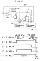
circuit 234 of Fig. 15. In thiscircuit 234, polarization control signal DS is used in place of select control signal SS. The polarization control signal DS and channel select signal CS, as issued fromCPU 176 for channel tuning, are input to exclusive ORcircuit 236 for recognizing the type of satellite. The output signal ofcircuit 236 is sent, as satellite type signal NI, toCPU 164 for antenna control. The signal NI and channel select signal CS as output fromCPU 164 for antenna control are input to another exclusive ORcircuit 238. The output signal ofcircuit 238 is input to the first input terminal ofselect switch 240. Polarization control signal DS is-input to the second input terminal ofswitch 240. The frequency scanning signal FS output fromCPU 176 for channel tuning is supplied toCPU 164 for channel control, and switch 240 is controlled by the output signal fromdelay 242. As described above, whensearch key 232 ofchannel controlling part 170 is pushed, frequency scanning signal FS goes "high" as shown in Fig. 16B, and the scanning of receiving frequencies starts. Normally,switch 240 is turned to the lower side as shown in Fig. 15. When signal FS goes "high", it is turned to the upper side, and polarization control signal DS is output toantenna 102, in the form of the output signal of receivingpolarization control circuit 234. - When polarization control signal DS goes "high" and receiving polarization control signal HV goes "high", as shown in Figs. 16C and 16D, the receiver is ready for receiving the vertically polarized wave, and all of the
channels 1 to 24 are scanned. Then, when both signals DS and HV go "low", it is ready for receiving the horizontally polarized wave. Under this condition, if thechannel 4 is received, frequency scanning signal FS goes "low", as shown in Fig. 16B. At this time, since channel select signal CS and polarization control signal DS are "low" as shown in Figs. 16A and 16C, exclusive ORcircuit 236 the "low" signal (indicating the normal satellite) as satellite type signal NI toCPU 164 for antenna control at time t21, as shown in Fig. 16E. - During the frequency scanning, the satellite type signal N1 supplied from
CPU 164 to exclusive ORcircuit 238 keeps an undefined state, i.e. "high" or "low" state. When the signal NI is produced as the output signal from exclusive ORcircuit 236, this value is transferred to exclusive ORcircuit 238. At time point t22 following time point t21 when frequency scanning signal FS goes "low",select switch 240 is again turned to the lower side. At this time, as the output signal of exclusive ORcircuit 238, an appropriate polarization has been determined using channel select signal CS and satellite type signal NI. The "low" signal is transferred as the receiving polarization control signal toantenna 102. - Also in this case, as in the previous embodiment, through
CPU 164, signal NI, together with the count corresponding to the satellite direction, is stored intomemory 160, with a predetermined label number attached thereto. A desired channel is also stored intomemory 178, with the equal label number attached thereto. In the viewing mode, the label number is designated and the desired channel is reproduced. - In the above-mentioned embodiments, two memories are used for storing the count corresponding to the antenna direction and the satellite type signal NI, and a desired channel, respectively. It is evident that these pieces of data may be storedlinto a single memory, with a specific label attached thereto. Further, the type of the memory is not limited to nonvolatile type.
- In the above-mentioned embodiments the amplitude of the output signal of
IF amplifier 182 is used for detecting presence or not of satellite broadcasting. Alternatively, this can be detected by detection of a sync signal from a sync separation circuit (not shown) ofvideo processing circuit 188. - Further, while the TV signal of each channel contains both the visual and aural signals, it may contain only aural signal. In this case, a speaker system is used in place of the display unit.
- It is needless to say that the label numbers may be substituted by alphabetic letters, such as A, B, C, etc., or by the combination of alphabetic letters and numbers, such as A1, F3, G4, etc..
- Since the nonvolatile memories are used for data storing, data is not volatilized if power supply is turned off, and after power on, it may be set in the viewing mode.
Claims (11)
Applications Claiming Priority (4)
| Application Number | Priority Date | Filing Date | Title |
|---|---|---|---|
| JP58183/85 | 1985-03-25 | ||
| JP5818385A JPS61218230A (en) | 1985-03-25 | 1985-03-25 | Satellite broadcast transmission and reception system |
| JP18585085A JPH0640625B2 (en) | 1985-08-26 | 1985-08-26 | Satellite broadcasting receiving system |
| JP185850/85 | 1985-08-26 |
Publications (3)
| Publication Number | Publication Date |
|---|---|
| EP0196607A2 true EP0196607A2 (en) | 1986-10-08 |
| EP0196607A3 EP0196607A3 (en) | 1988-01-13 |
| EP0196607B1 EP0196607B1 (en) | 1991-04-24 |
Family
ID=26399251
Family Applications (1)
| Application Number | Title | Priority Date | Filing Date |
|---|---|---|---|
| EP86104110A Expired EP0196607B1 (en) | 1985-03-25 | 1986-03-25 | A satellite broadcasting receiving system |
Country Status (3)
| Country | Link |
|---|---|
| US (1) | US4796032A (en) |
| EP (1) | EP0196607B1 (en) |
| DE (1) | DE3678861D1 (en) |
Cited By (11)
| Publication number | Priority date | Publication date | Assignee | Title |
|---|---|---|---|---|
| EP0276932A2 (en) * | 1987-01-29 | 1988-08-03 | Norsat International Inc. | Satellite receiver computer card |
| EP0285869A2 (en) * | 1987-04-09 | 1988-10-12 | BRIONVEGA S.p.A. | A tuning arrangement for the reception of television signals transmitted by earth stations and by satellites |
| EP0300193A1 (en) * | 1987-07-18 | 1989-01-25 | Deutsche Thomson-Brandt GmbH | Television set with an integrated satellite receiver unit |
| EP0220867A3 (en) * | 1985-10-21 | 1989-04-26 | Sony Corporation | Apparatus for receiving satellite broadcast signals |
| EP0314931A2 (en) * | 1987-11-02 | 1989-05-10 | BRIONVEGA S.p.A. | Method and apparatus for transmitting a plurality of control signals in antenna systems |
| EP0361885A2 (en) * | 1988-09-28 | 1990-04-04 | Gi Corporation | Satellite antenna alignment system |
| WO1991016768A1 (en) * | 1990-04-20 | 1991-10-31 | Ferguson Limited | Receiver for satellite reception |
| EP0493653A1 (en) * | 1990-12-31 | 1992-07-08 | Samsung Electronics Co. Ltd. | Color tv satellite broadcast receiver internally installed |
| EP0624029A1 (en) * | 1993-05-07 | 1994-11-09 | GRUNDIG E.M.V. Elektro-Mechanische Versuchsanstalt Max Grundig GmbH & Co. KG | Television receiver for the reception and reproduction of television signals with different vertical scanning frequencies |
| EP2398171A3 (en) * | 2010-06-17 | 2013-01-16 | Kabushiki Kaisha Toshiba | Antenna controlling apparatus and method for controlling antenna |
| WO2015184518A1 (en) * | 2014-06-04 | 2015-12-10 | Abreu João Do Espírito Santo | Parabolic antenna with self-structured reflector |
Families Citing this family (30)
| Publication number | Priority date | Publication date | Assignee | Title |
|---|---|---|---|---|
| US4862179A (en) * | 1985-03-26 | 1989-08-29 | Trio Kabushiki Kaisha | Satellite receiver |
| JPS6374202A (en) * | 1986-09-17 | 1988-04-04 | Nec Corp | Directivity adjusting device for earth station antenna |
| US4907003A (en) * | 1986-12-22 | 1990-03-06 | Microdyne Corporation | Satellite receiver and acquisiton system |
| JP2788560B2 (en) * | 1991-07-10 | 1998-08-20 | 富士通株式会社 | Receiving satellite switching device |
| JP2866775B2 (en) * | 1991-12-26 | 1999-03-08 | 三星電子株式会社 | Antenna moving device and method |
| US5347286A (en) * | 1992-02-13 | 1994-09-13 | Trimble Navigation Limited | Automatic antenna pointing system based on global positioning system (GPS) attitude information |
| US5287115A (en) * | 1992-07-10 | 1994-02-15 | General Instrument Corporation | Automatic adjustment of receiver apparatus based on channel-bit-error-rate-affected parameter measurement |
| US5313215A (en) * | 1992-07-10 | 1994-05-17 | General Instrument Corporation | Satellite identification and antenna alignment |
| JPH06152447A (en) * | 1992-10-30 | 1994-05-31 | Uniden Corp | Method and device for adjusting antenna direction for satellite broadcasting reception system |
| US5296861A (en) * | 1992-11-13 | 1994-03-22 | Trimble Navigation Limited | Method and apparatus for maximum likelihood estimation direct integer search in differential carrier phase attitude determination systems |
| TW252226B (en) * | 1994-06-09 | 1995-07-21 | Thomson Consumer Electronics | Antenna alignment apparatus and method utilizing the error condition of the received signal |
| US5561433A (en) * | 1994-06-09 | 1996-10-01 | Thomson Consumer Electronics, Inc. | Apparatus and method for aligning a receiving antenna utilizing an audible tone |
| KR960027050A (en) * | 1994-12-30 | 1996-07-22 | 김주용 | Passive Antenna Alignment Device and Method for Low Speed Data Terminal Station |
| US5742680A (en) * | 1995-11-13 | 1998-04-21 | E Star, Inc. | Set top box for receiving and decryption and descrambling a plurality of satellite television signals |
| US5771015A (en) * | 1995-11-20 | 1998-06-23 | Kirtman; Stuart E. | Controllable antenna system |
| US6011511A (en) * | 1996-11-07 | 2000-01-04 | Samsung Electronics Co., Ltd. | Satellite dish positioning system |
| US5961092A (en) * | 1997-08-28 | 1999-10-05 | Satellite Mobile Systems, Inc. | Vehicle with a satellite dish mounting mechanism for deployably mounting a satellite dish to the vehicle and method for deployably mounting a satellite dish to a vehicle |
| US6075330A (en) * | 1997-11-07 | 2000-06-13 | Terk Technologies Corp. | Outdoor antenna system with remote control and method for optimizing antenna function |
| JP3269458B2 (en) * | 1998-07-06 | 2002-03-25 | 株式会社村田製作所 | Antenna device and transmitting / receiving device |
| DE19938862C1 (en) | 1999-08-17 | 2001-03-15 | Kathrein Werke Kg | High frequency phase shifter assembly |
| US6697610B1 (en) * | 2000-06-15 | 2004-02-24 | Zenith Electronics Corporation | Smart antenna for RF receivers |
| US7006040B2 (en) | 2000-12-21 | 2006-02-28 | Hitachi America, Ltd. | Steerable antenna and receiver interface for terrestrial broadcast |
| DE10104564C1 (en) * | 2001-02-01 | 2002-09-19 | Kathrein Werke Kg | Control device for setting a different drop angle, in particular of mobile radio antennas belonging to a base station, and an associated antenna and method for changing a drop angle |
| KR20020086157A (en) * | 2001-05-11 | 2002-11-18 | 주식회사 한단정보통신 | An automatic satellite & channel searching system in the satellite broadcasting receiver which has a positioner and the automatic satellite & channel searching method thereof |
| US7149470B1 (en) * | 2002-04-04 | 2006-12-12 | The Directv Group, Inc. | Direct broadcast receiver utilizing LNB in cascade |
| JP4033178B2 (en) * | 2004-06-28 | 2008-01-16 | 船井電機株式会社 | Television broadcast receiving system and television broadcast receiving apparatus |
| US7774016B2 (en) * | 2007-02-19 | 2010-08-10 | Raven Antenna Systems Inc. | Satellite communications interoperability module and down-conversion method |
| FR2917932A1 (en) * | 2007-06-19 | 2008-12-26 | Thomson Licensing Sas | METHOD FOR DETECTING SATELLITE TRANSMISSION CHANNELS AND RECEPTION DEVICE USING THE METHOD. |
| US8050628B2 (en) * | 2007-07-17 | 2011-11-01 | M.N.C. Microsat Networks (Cyprus) Limited | Systems and methods for mitigating radio relay link interference in mobile satellite communications |
| WO2023050039A1 (en) * | 2021-09-28 | 2023-04-06 | 北京小米移动软件有限公司 | Information transmission method and apparatus, communication device, and storage medium |
Citations (3)
| Publication number | Priority date | Publication date | Assignee | Title |
|---|---|---|---|---|
| US4352202A (en) * | 1979-09-04 | 1982-09-28 | Carney Richard E | Combined remote control for wireless communication equipment and associated antenna |
| WO1983003243A1 (en) * | 1982-03-11 | 1983-09-29 | Wurdack Gerard A & Ass | Antenna rotator controller |
| CA1165401A (en) * | 1980-07-11 | 1984-04-10 | Michael S. Balbes | Receive only earth satellite ground station |
Family Cites Families (8)
| Publication number | Priority date | Publication date | Assignee | Title |
|---|---|---|---|---|
| FR2252663B1 (en) * | 1973-11-22 | 1978-12-01 | Gueguen Michel | |
| JPS5096703A (en) * | 1973-12-28 | 1975-08-01 | ||
| IT1108307B (en) * | 1978-09-25 | 1985-12-09 | Indesit | REFINEMENTS WITH SIGNAL SELECTION DEVICES WITH MEMORY |
| US4265265A (en) * | 1979-09-10 | 1981-05-05 | Chicago Pneumatic Tool Company | Pneumatic tool governor |
| JPS58137383A (en) * | 1982-02-10 | 1983-08-15 | Matsushita Electric Ind Co Ltd | Antenna controller of television receiver |
| US4602259A (en) * | 1982-07-12 | 1986-07-22 | Shepard John O | Polar mount antenna satellite tracking apparatus and method of alignment thereof |
| JPS6029244A (en) * | 1983-07-06 | 1985-02-14 | Mitsubishi Electric Corp | Electrical discharge machining device |
| JP3716557B2 (en) * | 1997-06-16 | 2005-11-16 | コニカミノルタホールディングス株式会社 | Liquid tank |
-
1986
- 1986-03-25 EP EP86104110A patent/EP0196607B1/en not_active Expired
- 1986-03-25 US US06/843,680 patent/US4796032A/en not_active Expired - Fee Related
- 1986-03-25 DE DE8686104110T patent/DE3678861D1/en not_active Expired - Lifetime
Patent Citations (3)
| Publication number | Priority date | Publication date | Assignee | Title |
|---|---|---|---|---|
| US4352202A (en) * | 1979-09-04 | 1982-09-28 | Carney Richard E | Combined remote control for wireless communication equipment and associated antenna |
| CA1165401A (en) * | 1980-07-11 | 1984-04-10 | Michael S. Balbes | Receive only earth satellite ground station |
| WO1983003243A1 (en) * | 1982-03-11 | 1983-09-29 | Wurdack Gerard A & Ass | Antenna rotator controller |
Non-Patent Citations (2)
| Title |
|---|
| PATENT ABSTRACTS OF JAPAN, vol. 4, no. 145 (E-29)[627], 14th October 1980; & JP-A-55 096 703 (SONY K.K.) 23-07-1980 * |
| PATENT ABSTRACTS OF JAPAN, vol. 7, no. 251 (E-209)[1396], 8th November 1983; & JP-A-58 137 383 (MATSUSHITA DENKI SANGYO K.K.) 15-08-1983 * |
Cited By (17)
| Publication number | Priority date | Publication date | Assignee | Title |
|---|---|---|---|---|
| EP0220867A3 (en) * | 1985-10-21 | 1989-04-26 | Sony Corporation | Apparatus for receiving satellite broadcast signals |
| EP0276932A2 (en) * | 1987-01-29 | 1988-08-03 | Norsat International Inc. | Satellite receiver computer card |
| EP0276932A3 (en) * | 1987-01-29 | 1990-10-31 | Norsat International Inc. | Satellite receiver computer card |
| EP0285869A2 (en) * | 1987-04-09 | 1988-10-12 | BRIONVEGA S.p.A. | A tuning arrangement for the reception of television signals transmitted by earth stations and by satellites |
| EP0285869A3 (en) * | 1987-04-09 | 1990-05-02 | BRIONVEGA S.p.A. | A tuning arrangement for the reception of television signals transmitted by earth stations and by satellites |
| EP0300193A1 (en) * | 1987-07-18 | 1989-01-25 | Deutsche Thomson-Brandt GmbH | Television set with an integrated satellite receiver unit |
| EP0314931A2 (en) * | 1987-11-02 | 1989-05-10 | BRIONVEGA S.p.A. | Method and apparatus for transmitting a plurality of control signals in antenna systems |
| EP0314931A3 (en) * | 1987-11-02 | 1990-05-16 | BRIONVEGA S.p.A. | Method and apparatus for transmitting a plurality of control signals in antenna systems |
| EP0361885A3 (en) * | 1988-09-28 | 1990-08-22 | General Instrument Corporation | Satellite antenna alignment system |
| EP0361885A2 (en) * | 1988-09-28 | 1990-04-04 | Gi Corporation | Satellite antenna alignment system |
| WO1991016768A1 (en) * | 1990-04-20 | 1991-10-31 | Ferguson Limited | Receiver for satellite reception |
| US5893023A (en) * | 1990-04-20 | 1999-04-06 | Ferguson Limited | Satellite receiver including operating voltage supply arrangement suitable for different antenna assemblies |
| EP0493653A1 (en) * | 1990-12-31 | 1992-07-08 | Samsung Electronics Co. Ltd. | Color tv satellite broadcast receiver internally installed |
| EP0624029A1 (en) * | 1993-05-07 | 1994-11-09 | GRUNDIG E.M.V. Elektro-Mechanische Versuchsanstalt Max Grundig GmbH & Co. KG | Television receiver for the reception and reproduction of television signals with different vertical scanning frequencies |
| EP2398171A3 (en) * | 2010-06-17 | 2013-01-16 | Kabushiki Kaisha Toshiba | Antenna controlling apparatus and method for controlling antenna |
| WO2015184518A1 (en) * | 2014-06-04 | 2015-12-10 | Abreu João Do Espírito Santo | Parabolic antenna with self-structured reflector |
| US10038250B2 (en) | 2014-06-04 | 2018-07-31 | João do Espírito Santo Abreu | Parabolic antenna with self-structured reflector |
Also Published As
| Publication number | Publication date |
|---|---|
| DE3678861D1 (en) | 1991-05-29 |
| EP0196607A3 (en) | 1988-01-13 |
| EP0196607B1 (en) | 1991-04-24 |
| US4796032A (en) | 1989-01-03 |
Similar Documents
| Publication | Publication Date | Title |
|---|---|---|
| US4796032A (en) | Satellite broadcasting receiving system | |
| JP3105462B2 (en) | Self-aligned satellite receiving antenna | |
| JPH05267919A (en) | Antenna moving device and its method | |
| US8466965B2 (en) | Wall plate digital television antenna signal meter and method | |
| JP3306999B2 (en) | Television receiver | |
| GR3029337T3 (en) | Improvements relating to satellite antennas | |
| US6069462A (en) | Remote control antenna rotor system | |
| JP2502419B2 (en) | Satellite receiver | |
| JPS61218230A (en) | Satellite broadcast transmission and reception system | |
| JPH08250920A (en) | Automatic direction converter for television antenna | |
| JPH0640625B2 (en) | Satellite broadcasting receiving system | |
| JPH0685502B2 (en) | Satellite broadcasting receiver | |
| JPH06105880B2 (en) | Satellite broadcasting receiving system | |
| JP2650254B2 (en) | Antenna monitoring device | |
| JP2605419B2 (en) | Satellite broadcast receiving antenna adjustment device | |
| EP0668625A1 (en) | Antenna with automatic alignment system for vehicles to a satellite | |
| KR100211246B1 (en) | System and method for automatically controlling antenna of tv receiver | |
| JPS62287732A (en) | Preset method of satellite broadcast reception system | |
| JPS5596703A (en) | Antenna unit | |
| EP0389494A1 (en) | Automatic polarization control system for tvro receivers | |
| JP2885300B2 (en) | Satellite positioning system | |
| KR0180677B1 (en) | Apparatus and method for automatically selecting the biased wave of a satellite broadcasting receiver | |
| JPH06104785A (en) | Satellite broadcast receiver | |
| JPS6019368Y2 (en) | Preset antenna automatic switching circuit in receiver | |
| CA2061589C (en) | Remote control antenna rotor system |
Legal Events
| Date | Code | Title | Description |
|---|---|---|---|
| PUAI | Public reference made under article 153(3) epc to a published international application that has entered the european phase |
Free format text: ORIGINAL CODE: 0009012 |
|
| 17P | Request for examination filed |
Effective date: 19860325 |
|
| AK | Designated contracting states |
Kind code of ref document: A2 Designated state(s): DE FR GB NL |
|
| RAP1 | Party data changed (applicant data changed or rights of an application transferred) |
Owner name: TOSHIBA AUDIO VIDEO ENGINEERING CO., LTD. Owner name: KABUSHIKI KAISHA TOSHIBA |
|
| PUAL | Search report despatched |
Free format text: ORIGINAL CODE: 0009013 |
|
| AK | Designated contracting states |
Kind code of ref document: A3 Designated state(s): DE FR GB NL |
|
| 17Q | First examination report despatched |
Effective date: 19891228 |
|
| GRAA | (expected) grant |
Free format text: ORIGINAL CODE: 0009210 |
|
| AK | Designated contracting states |
Kind code of ref document: B1 Designated state(s): DE FR GB NL |
|
| REF | Corresponds to: |
Ref document number: 3678861 Country of ref document: DE Date of ref document: 19910529 |
|
| ET | Fr: translation filed | ||
| PLBI | Opposition filed |
Free format text: ORIGINAL CODE: 0009260 |
|
| 26 | Opposition filed |
Opponent name: INTERESSENGEMEINSCHAFT FUER RUNDFUNKSCHUTZRECHTE E Effective date: 19920123 Opponent name: GRUNDIG E.M.V. ELEKTRO-MECHANISCHE VERSUCHSANSTALT Effective date: 19920122 |
|
| NLR1 | Nl: opposition has been filed with the epo |
Opponent name: INTERESSENGEMEINSCHAFT FUER RUNDFUNKSCHUTZRECHTE Opponent name: GRUNDIG E.M.V. |
|
| RAP2 | Party data changed (patent owner data changed or rights of a patent transferred) |
Owner name: TOSHIBA AVE CO., LTD Owner name: KABUSHIKI KAISHA TOSHIBA |
|
| NLT2 | Nl: modifications (of names), taken from the european patent patent bulletin |
Owner name: KABUSHIKI KAISHA TOSHIBA TE KAWASAKI EN TOSHIBA AV |
|
| PLAB | Opposition data, opponent's data or that of the opponent's representative modified |
Free format text: ORIGINAL CODE: 0009299OPPO |
|
| R26 | Opposition filed (corrected) |
Opponent name: GRUNDIG E.M.V. ELEKTRO-MECHANISCHE VERSUCHSANSTALT Effective date: 19920122 |
|
| NLR1 | Nl: opposition has been filed with the epo |
Opponent name: INTERESSENGEMEINSCHAFT FUER RUNDFUNKSCHUTZRECHTE E Opponent name: GRUNDIG E.M.V. ELEKTRO-MECHANISCHE VERSUCHSANSTALT |
|
| PLBN | Opposition rejected |
Free format text: ORIGINAL CODE: 0009273 |
|
| STAA | Information on the status of an ep patent application or granted ep patent |
Free format text: STATUS: OPPOSITION REJECTED |
|
| 27O | Opposition rejected |
Effective date: 19950914 |
|
| PGFP | Annual fee paid to national office [announced via postgrant information from national office to epo] |
Ref country code: FR Payment date: 19960126 Year of fee payment: 11 |
|
| NLR2 | Nl: decision of opposition | ||
| PGFP | Annual fee paid to national office [announced via postgrant information from national office to epo] |
Ref country code: GB Payment date: 19960318 Year of fee payment: 11 |
|
| PGFP | Annual fee paid to national office [announced via postgrant information from national office to epo] |
Ref country code: NL Payment date: 19960328 Year of fee payment: 11 Ref country code: DE Payment date: 19960328 Year of fee payment: 11 |
|
| PG25 | Lapsed in a contracting state [announced via postgrant information from national office to epo] |
Ref country code: GB Effective date: 19970325 |
|
| PG25 | Lapsed in a contracting state [announced via postgrant information from national office to epo] |
Ref country code: NL Effective date: 19971001 |
|
| GBPC | Gb: european patent ceased through non-payment of renewal fee |
Effective date: 19970325 |
|
| PG25 | Lapsed in a contracting state [announced via postgrant information from national office to epo] |
Ref country code: FR Free format text: LAPSE BECAUSE OF NON-PAYMENT OF DUE FEES Effective date: 19971128 |
|
| NLV4 | Nl: lapsed or anulled due to non-payment of the annual fee |
Effective date: 19971001 |
|
| PG25 | Lapsed in a contracting state [announced via postgrant information from national office to epo] |
Ref country code: DE Effective date: 19971202 |
|
| REG | Reference to a national code |
Ref country code: FR Ref legal event code: ST |
|
| APAH | Appeal reference modified |
Free format text: ORIGINAL CODE: EPIDOSCREFNO |