EP0195064B1 - A rock cavity - Google Patents
A rock cavity Download PDFInfo
- Publication number
- EP0195064B1 EP0195064B1 EP85904892A EP85904892A EP0195064B1 EP 0195064 B1 EP0195064 B1 EP 0195064B1 EP 85904892 A EP85904892 A EP 85904892A EP 85904892 A EP85904892 A EP 85904892A EP 0195064 B1 EP0195064 B1 EP 0195064B1
- Authority
- EP
- European Patent Office
- Prior art keywords
- rock
- cavity
- vertical
- ultimate
- holes
- Prior art date
- Legal status (The legal status is an assumption and is not a legal conclusion. Google has not performed a legal analysis and makes no representation as to the accuracy of the status listed.)
- Expired
Links
- 239000011435 rock Substances 0.000 title claims abstract description 68
- 239000012530 fluid Substances 0.000 claims abstract description 8
- 239000012265 solid product Substances 0.000 claims abstract description 3
- 238000004519 manufacturing process Methods 0.000 claims abstract 4
- 238000003860 storage Methods 0.000 claims description 27
- 238000005553 drilling Methods 0.000 claims description 22
- 238000000034 method Methods 0.000 claims description 16
- 238000005422 blasting Methods 0.000 claims description 14
- 230000002093 peripheral effect Effects 0.000 claims description 10
- 239000000126 substance Substances 0.000 claims description 2
- XLYOFNOQVPJJNP-UHFFFAOYSA-N water Substances O XLYOFNOQVPJJNP-UHFFFAOYSA-N 0.000 description 23
- 239000000047 product Substances 0.000 description 13
- 230000015572 biosynthetic process Effects 0.000 description 10
- 238000005755 formation reaction Methods 0.000 description 10
- 239000003921 oil Substances 0.000 description 8
- 238000010276 construction Methods 0.000 description 7
- 239000002360 explosive Substances 0.000 description 6
- 239000003673 groundwater Substances 0.000 description 5
- 239000007788 liquid Substances 0.000 description 5
- 239000003209 petroleum derivative Substances 0.000 description 4
- 239000011378 shotcrete Substances 0.000 description 4
- 238000009412 basement excavation Methods 0.000 description 3
- 239000000446 fuel Substances 0.000 description 3
- 239000010802 sludge Substances 0.000 description 3
- 239000000057 synthetic resin Substances 0.000 description 3
- 229920003002 synthetic resin Polymers 0.000 description 3
- 239000002131 composite material Substances 0.000 description 2
- 239000004567 concrete Substances 0.000 description 2
- 238000007796 conventional method Methods 0.000 description 2
- 239000003657 drainage water Substances 0.000 description 2
- 239000003822 epoxy resin Substances 0.000 description 2
- 238000009434 installation Methods 0.000 description 2
- 239000000463 material Substances 0.000 description 2
- 244000005700 microbiome Species 0.000 description 2
- 229920000647 polyepoxide Polymers 0.000 description 2
- 238000005086 pumping Methods 0.000 description 2
- 230000002285 radioactive effect Effects 0.000 description 2
- 239000003566 sealing material Substances 0.000 description 2
- 238000005507 spraying Methods 0.000 description 2
- 201000010001 Silicosis Diseases 0.000 description 1
- 239000003795 chemical substances by application Substances 0.000 description 1
- 239000002894 chemical waste Substances 0.000 description 1
- 239000010779 crude oil Substances 0.000 description 1
- 230000002939 deleterious effect Effects 0.000 description 1
- 230000008021 deposition Effects 0.000 description 1
- 238000013461 design Methods 0.000 description 1
- 239000000428 dust Substances 0.000 description 1
- 230000000694 effects Effects 0.000 description 1
- 230000007613 environmental effect Effects 0.000 description 1
- 239000004744 fabric Substances 0.000 description 1
- 230000002349 favourable effect Effects 0.000 description 1
- 239000003365 glass fiber Substances 0.000 description 1
- 230000001771 impaired effect Effects 0.000 description 1
- 238000002347 injection Methods 0.000 description 1
- 239000007924 injection Substances 0.000 description 1
- 238000007689 inspection Methods 0.000 description 1
- 239000000203 mixture Substances 0.000 description 1
- 238000012544 monitoring process Methods 0.000 description 1
- 230000002035 prolonged effect Effects 0.000 description 1
- 239000002901 radioactive waste Substances 0.000 description 1
- 238000011160 research Methods 0.000 description 1
- 238000007789 sealing Methods 0.000 description 1
- 238000007493 shaping process Methods 0.000 description 1
- 229920002379 silicone rubber Polymers 0.000 description 1
- 239000007921 spray Substances 0.000 description 1
- 239000002699 waste material Substances 0.000 description 1
Images




Classifications
-
- E—FIXED CONSTRUCTIONS
- E21—EARTH OR ROCK DRILLING; MINING
- E21D—SHAFTS; TUNNELS; GALLERIES; LARGE UNDERGROUND CHAMBERS
- E21D13/00—Large underground chambers; Methods or apparatus for making them
Definitions
- the present invention relates to a method for constructing cavities in rock formations, and particularly, although not exclusively, vertical cylindrical cavities intended for storing in rock petroleum products or other fluids, or solid products, such as chemicals, chemical waste, radioactive waste, and other material which are suited for storage in rock cavities.
- the object of the present invention is to provide a rock cavity for storing fluid and a method which will enable vertical cylindrical cavities to be constructed, blasted, in rock formations with the minimum explosive effect on residual cavity walls, while observing maximum safety conditions with respect to the working environment of the personnel involved in the construction of these cavities.
- SE-A-7802027-8 (pub No. 410 430) and 7901278-7 (pub. No. 425 305) describe and illustrate complexes for storing petroleum products and other fluids in rock formations. These storage complexes, or locations, have a very high storage capacity, despite being of relatively small horizontal extension. The stored product is therewith located within a concentrated area, and the expedient of shielding the storage area with a curtain of densely packed, waterfilled drill holes can therefore be more readily carried out, thereby to off-set lowering of the groundwater level and preventing the stored product from spreading to the complex surroundings.
- the cavities are located at substantially mutually equal depths, and when seen in horizontal section each cavity has a substantially circular or oval shape, and when seen in horizontal cross-section through the whole of the complex the mean points of the circular or oval horizontal sections of respective cavities lie in the corners of regular polygons, al having the same number of sides.
- regular polygon is meant a polygon in which all sides are of mutually equal length and all corner angles are the same.
- a regular polygon can thus be inscribed in a circle which passes through all of the corner points and the centre of which thus also forms the centre of the polygon.
- these polygons have the form of various sized pentagons having a common centre point.
- the cavities are therfore arranged in concentric circles.
- a further cavity can be arranged so that its centre axis coincides with the centre point of these circles.
- Rock cavites for storing oil or petroleum products of the prior art have the form of long "loaves", i.e. horizontally extending rock cavities presenting a bottom surface area of 500x25 m or thereabove, and a height of 30 m. It has been found that when storing oil products in rock cavities of this kind, in which the oil rests on a bed of water, microorganisms grow in the boundary layer between water and oil, the oil/oil products being destroyed thereby and rendered worthless for future use. When such cavities are used to store refined products, it has been found necessary to re-refine the products in order to quarantee their usefulness.
- a top tunnel from which the conically shaped roof cupola is taken, by first drilling holes obliquely outwards and downwards in the vicinity of the peripheral surface of the ultimate cupola or roof structure, filling these holes with explosives and blasting the rock; forming one or more transport tunnels so that said tunnels open into the cylindrical peripheral surface of the ultimate vertical rock cavity, excavation of rock being effected from the transport tunnels by vertical drilling and bench excavation operations, the shot rock-mass being taken-out at the bottom, which may taper conically downwards to a separate removal tunnel, which can be used for introducing piping and like conduits into the cavity site, and for removing goods stored in the cavity.
- the cavity walls be coated with an impervious composite lining comprising multi-layers of shotcrete, reinforced shotcrete, epoxy resin, glass fibre fabrics, and additionally epoxy resin.
- an impervious composite lining comprising multi-layers of shotcrete, reinforced shotcrete, epoxy resin, glass fibre fabrics, and additionally epoxy resin.
- Bench blasting h'as a highly deleterious affect on the residual cavity wall, and hence it is necessary, at high costs, to bolt the cavity wall and to line the same in order to achieve a durable result. Bench blasting also results in the formation of microfissures through which water in surrounding rock can enter the cavity.
- Bench blasting also presents a serious risk to the working environment of those responsible for drilling the holes.
- the method according to the invention is characterized by constructing from a transport tunnel an upper circumferential tunnel of larger external diameter than the diameter of the substantially cylindrical part of the ulitimate rock cavity, at a level above the highest ceiling level of said ultimate cavity; forming from a second transport tunnel a lower circumferential chamber of larger external diameter than the diameter of the substantially cylindrical part of the ultimate rock cavity at a level which lies not higher than the ultimate level of the lowermost point of the ultimate rock cavity; connecting these circumferential chambers by excavating a central vertical shaft and by excavating at least three vertical shafts at the periphery of the ulitimate cavity; ring drilling horizontally from the central shaft into the central rock mass in the ultimate cavity; fan drilling horizontal holes in the outer rock mass in the ultimate cavity, from the vertical peripheral shafts, so as to form a polygon of drill holes in a horizontal section through the ultimate rock cavity; drilling angled holes from the said peripheral shafts in a manner to form a conical roof
- the reference 1 identifies the periphery of an ultimate, substantially cylindrical and vertical cavity excavated from rock.
- the rock cavity When seen in horizontal section, the rock cavity has a polygonal cross-sectional form (in some cases a decagonal form).
- the ultimate outer contours of the cavity are shown in black, heavy lines, while the lighter drawn, full or broken lines show the cavity contours during construction.
- a transport tunnel 2 opens into an annular chamber 3, the diameter of which, or at least its outer diameter, is greater than the diameter of the ultimate rock cavity (30-40 m), said chamber 3 being constructed from the transport tunnel 2.
- a tunnel 5 which extends to a vertical shaft 6 intended for use as a waiting adit for horizontal/slightly sloping ring drilled holes in the rock mass to be blasted in the excavation of the rock cavity.
- a second transport tunnel 7 which extends to the bottom level of the ultimate rock cavity.
- a second annular tunnel 8 is excavated from this second transport tunnel 7 and the central vertical shaft 6 is joined to the second annular tunnel 8 by means of a horizontal tunnel 9.
- Side chambers 10 are excavated from the upper annular tunnel 3, inwardly of the rock mass.
- three or six vertical shafts 11 are formed between the side chambers 10 and the lower annular tunnel 8, these shafts being formed by tunnel boring upwards from below.
- This method involves drilling a narrow hole from above and downwards.
- a tunnel boring bit is connected in the tunnel 8 to a wire which extends through the hole and which during drilling is drawn from the bottom of the upwards.
- the drill bit When the drill bit has reached the top of the once narrow hole and the shaft has thus been completed, the drill bit is lowered to the bottom of the shaft and moved to the site of the next shaft, whereafter the procedure is repeated.
- holes 12 are ring drilled from the shaft 6 horizontally into the rock mass to be blasted.
- a relatively coarse drill diameter 10 cm, and drilling is continued to a distance of about 5 m from the ultimate cavity wall (40 times the hole diameter in centimeters).
- Horizontal holes 13 are fan drilled from the shaft 11 into the rock mass which is to be blasted out and which has not been perforated from the center. These holes are drilled with finer drills, e.g. drills of 20-40 mm in diameter.
- the outermost drill holes 13a are instrumental in forming the inner wall of the ultimate rock cavity.
- Holes which are instrumental in shaping the ceiling or roof structure 14 and the floor structure 15 of the cavity are drilled from the shaft 11. These holes are drilled from said shaft obliquely upwards and obliquely downwards at an angle of from 45-60°.
- the holes are filled with blasting explosives upon completion of a hole-drilling sequence.
- the drill holes extending outwardly from the central vertical shaft are filled with heavy explosive charges, whereas the holes drilled in the outer ring of rock-mass are charged with a lighter querlite explosive charge, 11-17 mm in diameter.
- Blasting is effected successively downwards, the rock is scaled and the shot rock-mass is taken out through the tunnel 9 with the aid of skips or front loaders.
- platforms can be automatically lowered down the vertical shafts, whereafter the fallen rock debris can be sprayed with water from water- canons, to bind all dust. This significantly reduces the risk of silicosis.
- the rock-mass can be readily sealed, by lowering lift or elevator platforms carrying high-pressure spray equipment down the peripheral shafts.
- the rock-mass can be treated with shotcrete from the same lift or elevator platforms as those used to scale the rock surfaces.
- the cavity walls are coated with a synthetic resin composite, from a collapsible/extendable platform structure, which is lowered down from the mouth of the central shaft and which comprises working platforms from which work can be carried out.
- the vertical shafts can be filled with a concrete construction, as illustrated in Fig. 1 by the reference 20.
- the drainage pipes are led out through the concrete construction.
- Fig. 1 only illustrates a few of the total number of drill holes required for blasting at each level.
- the drainage holes 17 drilled behind the cavity walls 1 may suitably be connected vertically at each corner of a polygon where no vertical shaft is located, by means of vertical holes 21. These vertical holes 21 may also be used to blow hot air through the drainage holes 17 in groups or sections, and in this way dry/heat the cavity wall prior to applying the synthetic resin lining thereto.
- drainage holes 17 are suitably drilled from the annular tunnel 3 at the roof level, in towards the centre, as illustrated in Fig. 2.
- an umbrella of drainage holes 17 is drilled from the centrally located rock chute 22 outwardly to an area externally of the cavity wall. Drainage water can be removed from the rock chute 22 via pipes not shown.
- the vertical shafts 11 may comprise an active storage part of the overall storage facility, or may alternatively play no part therein, depending on the type of fluid to be stored.
- these shafts play no active storage part, and hence there is introduced into the rock chute above the drainage area a bottom structure through which pipes (not shown) are drawn for pumping away the jet fuel.
- the whole of the tunnel and shaft system may form active storage locations, in which case there is inserted in the tunnel 7 a plug through which oil-pumping pipes are drawn.
- the complex illustrated in Fig. 4 thus includes a plurality of polygonal cavities formed in the rock-mass, each of these cavities having a substantially cylindrical shape, and each cavity forming a storage space, the rock-formed walls of which directly absorb the pressure exerted by the fluid stored in the cavity, the centre axes of the cavities extending vertically.
- Each cavity suitably has a vertical height which is greater than or equal to its diameter in cross-section.
- the storage complex is compact and requires the minimum of surface area. It is thus possible to construct very large storage complexes within limited areas. The area of the storage region is minimal. This greatly facilitates provision of those means required to avoid lowering of the ambient ground water.
- the geometric configuration of the storage complex also facilitates provision of water curtains externally of the storage complex. These water curtains comprise rows of vertical drill holes filled with water. The groundwater level can be maintained within the storage complex and externally thereof with the aid of such water curtains.
- the fact that the storage complex can be constructed within a compact area enables the complex to be readily excavated from a homogeneous rock-mass, thereby avoiding disturbances in the surroundings more readily.
- eacn cavity has a height which is greater than its diameter
- the rock-mass in which the complex is constructed can be utilized more favorably to great depths, which enables a more compact storage complex to be constructed and a more favorable economy to be achieved with regard to the use of available ground area, and also provides improved heat economy when the stored product is heated.
- this heat can be supplied to any desired part of the cavities at any desired level.
- the sludge can readily be collected and pumped away from the storage complex, and it is not necessary to arrange large collecting spaces for the final deposition of sludge in the bottom of the complex.
- the particular form of the cavities also facilitates the installation of monitoring sensors, for example temperature responsive means and level indicators, and the like.
- monitoring sensors for example temperature responsive means and level indicators, and the like.
- the rock-mass can be sealed by injecting a sealing material through drill holes.
- This sealing material may be a silicone elastomer or the like.
- the storage space is dry, it can also be used to store low radioactive and average radioactive nuclear waste deriving from nuclear power stations and nuclear research stations, in addition to the aforesaid products.
- the rock cavity according to the present invention eliminates all problems known at present with the oil storage technique.
- the pumpability of oil stored compared with horizontal storage loaves provides a volumetric gain in storage facilities which can be calculated in multi-million sums of currency in storage costs over an operational time of 20 years.
- the method according to the invention affords the advantage of a rapid tunnel-driving method; precise contour drilling; optimal placement of injection holes; blasted rock-mass can be removed independently of drilling; 80% of the drilled volume is coarse ring drilling; personnel need not enter the rock cavity, because of the presence of the vertical shafts; worker protection and ergonometry is improved by the vertical shafts; shorter construction times in comparison with conventional techniques and lower blasting costs are achieved.
- the costs saving compared with conventional technique for a rock storage complex having a volumetric capacity of 500,000 m 3 can be estimated to be at least 20 MSEK.
Landscapes
- Engineering & Computer Science (AREA)
- Mining & Mineral Resources (AREA)
- Life Sciences & Earth Sciences (AREA)
- General Life Sciences & Earth Sciences (AREA)
- Geochemistry & Mineralogy (AREA)
- Geology (AREA)
- Lining And Supports For Tunnels (AREA)
- Farming Of Fish And Shellfish (AREA)
- Earth Drilling (AREA)
Abstract
Description
- The present invention relates to a method for constructing cavities in rock formations, and particularly, although not exclusively, vertical cylindrical cavities intended for storing in rock petroleum products or other fluids, or solid products, such as chemicals, chemical waste, radioactive waste, and other material which are suited for storage in rock cavities.
- The object of the present invention is to provide a rock cavity for storing fluid and a method which will enable vertical cylindrical cavities to be constructed, blasted, in rock formations with the minimum explosive effect on residual cavity walls, while observing maximum safety conditions with respect to the working environment of the personnel involved in the construction of these cavities.
- It is previously known to store petroleum products and also other liquids lighter than water, in a cavity formed in groundwater carrying rock formations, in which the stored liquid lies in direct contact with water-permeable surface of the cavity walls. The pressure exerted on the cavity walls by the liquid stored in the cavity is less than the pressure exerted by surrounding ground water, thereby counteracting any tendency of the stored liquid to pass through the wall.
- When the stored liquid is lighter than water and insoluble therein, it is normal practice to provide a water bed in the lowermost region of the cavity.
- SE-A-7802027-8 (pub No. 410 430) and 7901278-7 (pub. No. 425 305) describe and illustrate complexes for storing petroleum products and other fluids in rock formations. These storage complexes, or locations, have a very high storage capacity, despite being of relatively small horizontal extension. The stored product is therewith located within a concentrated area, and the expedient of shielding the storage area with a curtain of densely packed, waterfilled drill holes can therefore be more readily carried out, thereby to off-set lowering of the groundwater level and preventing the stored product from spreading to the complex surroundings.
- According to these patent apecifications, the cavities are located at substantially mutually equal depths, and when seen in horizontal section each cavity has a substantially circular or oval shape, and when seen in horizontal cross-section through the whole of the complex the mean points of the circular or oval horizontal sections of respective cavities lie in the corners of regular polygons, al having the same number of sides.
- By regular polygon is meant a polygon in which all sides are of mutually equal length and all corner angles are the same. A regular polygon can thus be inscribed in a circle which passes through all of the corner points and the centre of which thus also forms the centre of the polygon.
- In accordance with one embodiment of the afore mentioned SE-documents these polygons have the form of various sized pentagons having a common centre point. The cavities are therfore arranged in concentric circles. A further cavity can be arranged so that its centre axis coincides with the centre point of these circles.
- It is also known from SE-A-8300185-9 to construct in rock formations a fluid-storage cavity location in which the actual cavity has the form of a substantially vertical cylinder, around which there is provided a series of vertical holes forming a water-drainage shield; this drainage shield is intended for removal of the water bed upon which the stored fluid has rested.
- Rock cavites for storing oil or petroleum products of the prior art have the form of long "loaves", i.e. horizontally extending rock cavities presenting a bottom surface area of 500x25 m or thereabove, and a height of 30 m. It has been found that when storing oil products in rock cavities of this kind, in which the oil rests on a bed of water, microorganisms grow in the boundary layer between water and oil, the oil/oil products being destroyed thereby and rendered worthless for future use. When such cavities are used to store refined products, it has been found necessary to re-refine the products in order to quarantee their usefulness.
- In order to overcome these problems associated with horizontal cavities, the use of vertical, substantially cylindrical rock cavities has been proposed, as beforementioned. Examples of such vertical cavities are described and illustrated in SE-A-7901278-7 and SE-A-8300185-9, and in subsequent articles by K.I. Sagefors et al, WP-System, Stockholm, Sweden. When excavating the rock in the construction of such vertical cavities, there is first formed a top tunnel from which the conically shaped roof cupola is taken, by first drilling holes obliquely outwards and downwards in the vicinity of the peripheral surface of the ultimate cupola or roof structure, filling these holes with explosives and blasting the rock; forming one or more transport tunnels so that said tunnels open into the cylindrical peripheral surface of the ultimate vertical rock cavity, excavation of rock being effected from the transport tunnels by vertical drilling and bench excavation operations, the shot rock-mass being taken-out at the bottom, which may taper conically downwards to a separate removal tunnel, which can be used for introducing piping and like conduits into the cavity site, and for removing goods stored in the cavity.
- As mentioned above, previous methods for constructing substantially cylindrical, vertical cavities from rock formations have involved driving a top tunnel from which drilling takes place. This necessitates the provision of a large number of drill holes and therewith an excessive charge of explosives, which places the roof of the cavity under unnecessary strain. Construction'of the top tunnel also results in disturbance of the rock located above the cavity, with subsequent risk of impaired strength.
- Upon discovery that microorganisms grow in the boundary layer between the product stored and the water present, it was demanded that any water present should be kept to a minimum, and it was further proposed in conjunction herewith that the cavity walls be coated with an impervious composite lining comprising multi-layers of shotcrete, reinforced shotcrete, epoxy resin, glass fibre fabrics, and additionally epoxy resin. One such cavity-lining method is described by Beck- ers-Sigman, COLTURIET products.
- It is not certain, however, that a lining of this nature would be able to provide durable protection should the lining be subjected constantly to water pressure on the rock side thereof. Consequently, in order to guarantee prolonged resistance of the lining, additional methods have been proposed for eliminating ambient water (SE-A-8300185-9).
- It has been found that bench blasting h'as a highly deleterious affect on the residual cavity wall, and hence it is necessary, at high costs, to bolt the cavity wall and to line the same in order to achieve a durable result. Bench blasting also results in the formation of microfissures through which water in surrounding rock can enter the cavity.
- Bench blasting also presents a serious risk to the working environment of those responsible for drilling the holes.
- For reasons of a technical and environmental nature, there has now been raised a demand for a new method of excavating vertical rock cavities.
- It has been found that the present invention surprisingly meets all of these demands. The method according to the invention is characterized by constructing from a transport tunnel an upper circumferential tunnel of larger external diameter than the diameter of the substantially cylindrical part of the ulitimate rock cavity, at a level above the highest ceiling level of said ultimate cavity; forming from a second transport tunnel a lower circumferential chamber of larger external diameter than the diameter of the substantially cylindrical part of the ultimate rock cavity at a level which lies not higher than the ultimate level of the lowermost point of the ultimate rock cavity; connecting these circumferential chambers by excavating a central vertical shaft and by excavating at least three vertical shafts at the periphery of the ulitimate cavity; ring drilling horizontally from the central shaft into the central rock mass in the ultimate cavity; fan drilling horizontal holes in the outer rock mass in the ultimate cavity, from the vertical peripheral shafts, so as to form a polygon of drill holes in a horizontal section through the ultimate rock cavity; drilling angled holes from the said peripheral shafts in a manner to form a conical roof arch and/ or a conical base profile; and by blasting from the bottom upwards in a consecutive series of blasting operations, to form a polygonal, vertical rock cavity.
- These and other characteristic features of the invention are set forth in the following claims.
- When excavating cavities in rock formations in accordance with the invention, serious crack formations are less likely to occur in the cavity walls. In addition, all drilling work is effected from the vertical shafts; the drillers are located in the protection of the shafts and therefore need never enter the cavity. Blasting can be effected from below, wherewith the drillers can quickly re-take their working position in the shafts.
- The invention will now be described in more detail with reference to the accompanying drawings, in which
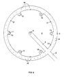
- Figure 1 illustrates in horizontal section a preferred embodiment of a rock cavity constructed in accordance with the invention;
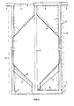
- Figure 2 is a vertical sectional view of the embodiment illustrated in Figure 1;
- Figure 3 is a horizontal sectional view of the upper part of the rock facility according to Figure 1;
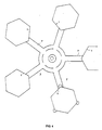
- Figure 4 is a horizontal sectional view of a complex comprising a plurality of rock cavities according to Figures 1-3;
- Figures 5-11 illustrate various sequencies in constructing the cavity from rock formations, of which figures
- Figure 5 illustrates the drilling of holes from the central shaft;
- Figure 6 illustrates the drilling of finer holes in the outer part, and the drilling of drainage holes from the peripheral shafts;
- Figure 7 illustrates the scaling of the cavity walls with water under high pressure;
- Figure 8 illustrates the step of spraying the cavity walls with shotcrete;
- Figure 9 illustrates the introduction of a platform into the central shaft;
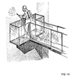
- Figure 10 illustrates the step of spraying the cavity walls with a synthetic resin composition; and
- Figure 11 illustrates inspection of the drainage system.
- In the drawings the
reference 1 identifies the periphery of an ultimate, substantially cylindrical and vertical cavity excavated from rock. When seen in horizontal section, the rock cavity has a polygonal cross-sectional form (in some cases a decagonal form). The ultimate outer contours of the cavity are shown in black, heavy lines, while the lighter drawn, full or broken lines show the cavity contours during construction. Atransport tunnel 2 opens into anannular chamber 3, the diameter of which, or at least its outer diameter, is greater than the diameter of the ultimate rock cavity (30-40 m), saidchamber 3 being constructed from thetransport tunnel 2. In the residual core mass 4 located within the annular chamber ortunnel 3 there is now formed atunnel 5 which extends to a vertical shaft 6 intended for use as a waiting adit for horizontal/slightly sloping ring drilled holes in the rock mass to be blasted in the excavation of the rock cavity. When constructing thetransport tunnel 2 there is formed at the same time asecond transport tunnel 7 which extends to the bottom level of the ultimate rock cavity. A secondannular tunnel 8 is excavated from thissecond transport tunnel 7 and the central vertical shaft 6 is joined to the secondannular tunnel 8 by means of a horizontal tunnel 9.Side chambers 10 are excavated from the upperannular tunnel 3, inwardly of the rock mass. In the illustrated embodiments, three or sixvertical shafts 11 are formed between theside chambers 10 and the lowerannular tunnel 8, these shafts being formed by tunnel boring upwards from below. - This method involves drilling a narrow hole from above and downwards. A tunnel boring bit is connected in the
tunnel 8 to a wire which extends through the hole and which during drilling is drawn from the bottom of the upwards. When the drill bit has reached the top of the once narrow hole and the shaft has thus been completed, the drill bit is lowered to the bottom of the shaft and moved to the site of the next shaft, whereafter the procedure is repeated. - As beforementioned, holes 12 are ring drilled from the shaft 6 horizontally into the rock mass to be blasted. In this case there is used a relatively coarse drill,
diameter 10 cm, and drilling is continued to a distance of about 5 m from the ultimate cavity wall (40 times the hole diameter in centimeters). Horizontal holes 13 are fan drilled from theshaft 11 into the rock mass which is to be blasted out and which has not been perforated from the center. These holes are drilled with finer drills, e.g. drills of 20-40 mm in diameter. The outermost drill holes 13a are instrumental in forming the inner wall of the ultimate rock cavity. These relatively fine holes are not normally drilled to distances in excess of 10 m, since it is difficult to control the self- steering of the drill at distances greater than this. Consequently the sides of the polygon are seldom longer than 10 m. - Holes which are instrumental in shaping the ceiling or
roof structure 14 and thefloor structure 15 of the cavity are drilled from theshaft 11. These holes are drilled from said shaft obliquely upwards and obliquely downwards at an angle of from 45-60°. - The holes are filled with blasting explosives upon completion of a hole-drilling sequence. The drill holes extending outwardly from the central vertical shaft are filled with heavy explosive charges, whereas the holes drilled in the outer ring of rock-mass are charged with a lighter querlite explosive charge, 11-17 mm in diameter.
- Blasting is effected successively downwards, the rock is scaled and the shot rock-mass is taken out through the tunnel 9 with the aid of skips or front loaders.
- As soon as a blasting salvo has terminated, platforms can be automatically lowered down the vertical shafts, whereafter the fallen rock debris can be sprayed with water from water- canons, to bind all dust. This significantly reduces the risk of silicosis.
- In order to seal-off the rock-mass externally of the cavity complex,
vertical holes 16 are drilled from the upperannular tunnel 3 straight down through the rock-mass, to the level of the cavity bottom. A sealing agent is then injected into these holes, so as to fill the micro-cracks and macro-cracks in the rock-mass. - Subsequent to excavating the complete cavity, the rock-mass can be readily sealed, by lowering lift or elevator platforms carrying high-pressure spray equipment down the peripheral shafts.
- When desiring a more impervious surface, the rock-mass can be treated with shotcrete from the same lift or elevator platforms as those used to scale the rock surfaces.
- In certain cases, when storing fuel for civilian and military jet aircraft, totally impervious surfaces are required, so as to totally eliminate the presence of water. In this case the cavity walls are coated with a synthetic resin composite, from a collapsible/extendable platform structure, which is lowered down from the mouth of the central shaft and which comprises working platforms from which work can be carried out.
- In order to eliminate the water pressure exerted by water in the surrounding rock-mass, it is necessary to drain this water away. This is effected by drilling drainage holes 17 in the rock-mass from the peripherally located
vertical shafts 11. The drill holes 17 are placed so close together that water moving towards the rock cavity is captured and carred away thereby. Theholes 17 slope slightly downwards towards thevertical shafts 11 and discharge thereinto. The drainage water runs behind awall 18 cast in respectivevertical shafts 11, and can therewith be readily pumped away from the bottom of said shafts. Elevators can be mounted in the remaining part of theshafts 11, so that the shafts can be monitored with respect to water drainage. - Alternatively, when blasting is completed, the vertical shafts can be filled with a concrete construction, as illustrated in Fig. 1 by the
reference 20. In this case the drainage pipes are led out through the concrete construction. It will be understood that Fig. 1 only illustrates a few of the total number of drill holes required for blasting at each level. - The drainage holes 17 drilled behind the
cavity walls 1 may suitably be connected vertically at each corner of a polygon where no vertical shaft is located, by means ofvertical holes 21. Thesevertical holes 21 may also be used to blow hot air through the drainage holes 17 in groups or sections, and in this way dry/heat the cavity wall prior to applying the synthetic resin lining thereto. - In order to drain the roof region of the cavity, drainage holes 17 are suitably drilled from the
annular tunnel 3 at the roof level, in towards the centre, as illustrated in Fig. 2. Conversely, for the purpose of draining the bottom region of the cavity an umbrella of drainage holes 17 is drilled from the centrally locatedrock chute 22 outwardly to an area externally of the cavity wall. Drainage water can be removed from therock chute 22 via pipes not shown. - The
vertical shafts 11 may comprise an active storage part of the overall storage facility, or may alternatively play no part therein, depending on the type of fluid to be stored. When storing jet fuel these shafts play no active storage part, and hence there is introduced into the rock chute above the drainage area a bottom structure through which pipes (not shown) are drawn for pumping away the jet fuel. When storing crude oil, the whole of the tunnel and shaft system may form active storage locations, in which case there is inserted in the tunnel 7 a plug through which oil-pumping pipes are drawn. - The complex illustrated in Fig. 4 thus includes a plurality of polygonal cavities formed in the rock-mass, each of these cavities having a substantially cylindrical shape, and each cavity forming a storage space, the rock-formed walls of which directly absorb the pressure exerted by the fluid stored in the cavity, the centre axes of the cavities extending vertically. Each cavity suitably has a vertical height which is greater than or equal to its diameter in cross-section.
- The storage complex is compact and requires the minimum of surface area. It is thus possible to construct very large storage complexes within limited areas. The area of the storage region is minimal. This greatly facilitates provision of those means required to avoid lowering of the ambient ground water. The geometric configuration of the storage complex also facilitates provision of water curtains externally of the storage complex. These water curtains comprise rows of vertical drill holes filled with water. The groundwater level can be maintained within the storage complex and externally thereof with the aid of such water curtains. The fact that the storage complex can be constructed within a compact area enables the complex to be readily excavated from a homogeneous rock-mass, thereby avoiding disturbances in the surroundings more readily.
- Since eacn cavity has a height which is greater than its diameter, the rock-mass in which the complex is constructed can be utilized more favorably to great depths, which enables a more compact storage complex to be constructed and a more favorable economy to be achieved with regard to the use of available ground area, and also provides improved heat economy when the stored product is heated.
- As a result of the considerable height of respective cavities, the head obtained is sufficient to enable the product to be readily pumped away with the aid of pumps arranged beneath said cavities. The compact design of the storage complex also means that the requisite pipe installations will be less expensive than would otherwise be the case.
- If the stored product is to be heated, this heat can be supplied to any desired part of the cavities at any desired level.
- If the stored products deposit slime or sludge, the sludge can readily be collected and pumped away from the storage complex, and it is not necessary to arrange large collecting spaces for the final deposition of sludge in the bottom of the complex.
- The particular form of the cavities also facilitates the installation of monitoring sensors, for example temperature responsive means and level indicators, and the like. When the space is used as a machinery room, material transport can be effected with the aid of overhead cranes.
- As beforementioned, the rock-mass can be sealed by injecting a sealing material through drill holes. This sealing material may be a silicone elastomer or the like.
- Because the storage space is dry, it can also be used to store low radioactive and average radioactive nuclear waste deriving from nuclear power stations and nuclear research stations, in addition to the aforesaid products.
- The rock cavity according to the present invention eliminates all problems known at present with the oil storage technique. The pumpability of oil stored compared with horizontal storage loaves provides a volumetric gain in storage facilities which can be calculated in multi-million sums of currency in storage costs over an operational time of 20 years.
- The method according to the invention affords the advantage of a rapid tunnel-driving method; precise contour drilling; optimal placement of injection holes; blasted rock-mass can be removed independently of drilling; 80% of the drilled volume is coarse ring drilling; personnel need not enter the rock cavity, because of the presence of the vertical shafts; worker protection and ergonometry is improved by the vertical shafts; shorter construction times in comparison with conventional techniques and lower blasting costs are achieved. The costs saving compared with conventional technique for a rock storage complex having a volumetric capacity of 500,000 m3 can be estimated to be at least 20 MSEK.
Claims (6)
Priority Applications (1)
| Application Number | Priority Date | Filing Date | Title |
|---|---|---|---|
| AT85904892T ATE39160T1 (en) | 1984-09-20 | 1985-09-18 | ROCK EXCAVATION. |
Applications Claiming Priority (2)
| Application Number | Priority Date | Filing Date | Title |
|---|---|---|---|
| SE8404728A SE452785B (en) | 1984-09-20 | 1984-09-20 | PROCEDURE FOR REPLACING A BACKGROUND AND BACKGROUND PREPARED ACCORDING TO THE PROCEDURE |
| SE8404728 | 1984-09-20 |
Publications (2)
| Publication Number | Publication Date |
|---|---|
| EP0195064A1 EP0195064A1 (en) | 1986-09-24 |
| EP0195064B1 true EP0195064B1 (en) | 1988-12-07 |
Family
ID=20357084
Family Applications (1)
| Application Number | Title | Priority Date | Filing Date |
|---|---|---|---|
| EP85904892A Expired EP0195064B1 (en) | 1984-09-20 | 1985-09-18 | A rock cavity |
Country Status (7)
| Country | Link |
|---|---|
| US (1) | US4708523A (en) |
| EP (1) | EP0195064B1 (en) |
| JP (1) | JPS62500253A (en) |
| DE (1) | DE3566703D1 (en) |
| SE (1) | SE452785B (en) |
| SG (1) | SG103991G (en) |
| WO (1) | WO1986001854A1 (en) |
Families Citing this family (19)
| Publication number | Priority date | Publication date | Assignee | Title |
|---|---|---|---|---|
| WO1988008608A1 (en) * | 1987-04-22 | 1988-11-03 | Uwe Eggert | Store |
| JPH07107359B2 (en) * | 1988-06-15 | 1995-11-15 | 株式会社小松製作所 | Underground cavity construction method and tunnel excavator |
| SE465171B (en) * | 1989-12-06 | 1991-08-05 | K Svensson | PROCEDURE BEFORE SELECTION OF MOUNTAIN SPACES |
| DE4140236A1 (en) * | 1991-12-06 | 1993-04-22 | Daimler Benz Ag | INDEPENDENT WHEEL SUSPENSION FOR MOTOR VEHICLES |
| SE504669C2 (en) * | 1994-03-27 | 1997-03-24 | Karl Ivar Sagefors | Procedure for the removal of rock cavities |
| CA2518858A1 (en) * | 2003-03-14 | 2004-09-30 | Avery Dennison Corporation | Housewrap |
| CH699755B1 (en) * | 2007-08-23 | 2012-05-31 | Espros Photonics Ag | Semiconductor factory. |
| SE536723C2 (en) * | 2012-11-01 | 2014-06-24 | Skanska Sverige Ab | Thermal energy storage including an expansion space |
| RU2651820C1 (en) * | 2014-06-13 | 2018-04-24 | Чанцзян Сервей Плэннинг Дизайн Энд Рисерч Ко., Лтд. | Rings construction scheme of underground workings group of radiation part of underground nuclear power plant |
| WO2015188693A1 (en) * | 2014-06-13 | 2015-12-17 | 长江勘测规划设计研究有限责任公司 | Construction layout of underground nuclear power station nuclear island plant underground cavern group being perpendicular to mountain depth direction |
| US11220815B2 (en) | 2016-04-21 | 2022-01-11 | Bio Clean Environmental Services, Inc. | Underground storage system with V shaped support legs |
| US10151083B2 (en) | 2016-04-21 | 2018-12-11 | Bio Clean Environmental Services, Inc. | Honeycomb module and underground storage system |
| US10151096B2 (en) | 2016-04-21 | 2018-12-11 | Bio Clean Environmental Services, Inc. | Tessellation square module and underground storage system |
| US9732508B1 (en) | 2016-04-21 | 2017-08-15 | Bio Clean Environmental Services, Inc. | Hexagonal module and assembly for storage of water underground |
| US11952767B2 (en) * | 2016-09-13 | 2024-04-09 | Bio Clean Environmental Services, Inc. | Underground storage system with V shaped support legs |
| USD795384S1 (en) * | 2016-06-10 | 2017-08-22 | Bio Clean Environmental Services, Inc. | Hexagonal water storage module |
| USD795385S1 (en) * | 2016-07-13 | 2017-08-22 | Bio Clean Environmental Services, Inc. | Underground module for storage of water |
| US11980835B2 (en) * | 2020-07-27 | 2024-05-14 | Foley Products Company, Llc | Double-filter basket for stormwater retention system drain |
| CN113404496B (en) * | 2021-06-30 | 2023-03-21 | 中建八局第二建设有限公司 | Construction method of limited space ultra-deep shaft |
Family Cites Families (10)
| Publication number | Priority date | Publication date | Assignee | Title |
|---|---|---|---|---|
| US1347934A (en) * | 1919-10-01 | 1920-07-27 | Joseph F Brown | Air or water pressure tank |
| GB660335A (en) * | 1949-09-22 | 1951-11-07 | Svenska Entreprenad Aktiebolag | Improvements in and relating to storage tanks for liquid fuel and the like |
| US3068654A (en) * | 1958-09-22 | 1962-12-18 | Interstate Service Corp | Underground storage cavern and method of making same |
| US3701262A (en) * | 1970-10-12 | 1972-10-31 | Systems Capital Corp | Means for the underground storage of liquified gas |
| SE7308359L (en) * | 1973-06-14 | 1974-12-16 | Arne Lorens Beckstrom | |
| GB2017797B (en) * | 1978-02-21 | 1982-06-03 | Sagefors K | System for the storage of petroleum products and other fluids in a rock |
| SE410430B (en) * | 1978-02-21 | 1979-10-15 | Hallenius Tore Jerker | FACILITY FOR STORAGE OF PETROLEUM PRODUCTS AND OTHER FLUIDA IN BERG |
| SE434969B (en) * | 1983-01-14 | 1984-08-27 | Boliden Ab | PROCEDURE FOR BLASTING THE BERG SPACE |
| DE3335044C2 (en) * | 1983-09-28 | 1985-09-12 | Klaus-Rüdiger 2945 Sande Smigoski | Containers for the transport and subsequent dumping of hazardous waste in the ground or in the oceans, as well as processes for the manufacture and closure of such a container |
| SE442927B (en) * | 1984-04-10 | 1986-02-03 | Boliden Ab | PLANT FOR STORAGE OF RADIOACTIVE MATERIAL IN BERG |
-
1984
- 1984-09-20 SE SE8404728A patent/SE452785B/en not_active IP Right Cessation
-
1985
- 1985-09-18 DE DE8585904892T patent/DE3566703D1/en not_active Expired
- 1985-09-18 EP EP85904892A patent/EP0195064B1/en not_active Expired
- 1985-09-18 JP JP60504390A patent/JPS62500253A/en active Pending
- 1985-09-18 US US06/871,398 patent/US4708523A/en not_active Expired - Fee Related
- 1985-09-18 WO PCT/SE1985/000357 patent/WO1986001854A1/en not_active Ceased
-
1991
- 1991-12-07 SG SG1039/91A patent/SG103991G/en unknown
Also Published As
| Publication number | Publication date |
|---|---|
| SE8404728L (en) | 1986-03-21 |
| EP0195064A1 (en) | 1986-09-24 |
| WO1986001854A1 (en) | 1986-03-27 |
| SE8404728D0 (en) | 1984-09-20 |
| US4708523A (en) | 1987-11-24 |
| SE452785B (en) | 1987-12-14 |
| JPS62500253A (en) | 1987-01-29 |
| SG103991G (en) | 1992-02-14 |
| DE3566703D1 (en) | 1989-01-12 |
Similar Documents
| Publication | Publication Date | Title |
|---|---|---|
| US4708523A (en) | Rock cavity | |
| US4363563A (en) | System for the storage of petroleum products and other fluids in a rock | |
| CN113530558B (en) | Double-drop shaft-inclined drift combined layered construction method for high-large chamber | |
| CN103470267B (en) | The one Rapid Construction of Tunnels technique of growing up | |
| US4725164A (en) | Method of excavating a storage complex in rock for storing radioactive waste | |
| CN105569693A (en) | Underground stable rock stratum large-scale chamber construction method applied to medium-length hole blasting | |
| EP0132269B1 (en) | A method of excavating underground caverns in rock | |
| EP0098266B1 (en) | A method for constructing in rock storage locations for liquid products, for example oil products | |
| CN115655040A (en) | Safe construction method of large-section hard rock lithologic ore pass | |
| CN114086964A (en) | Mine non-blasting vertical shaft construction method | |
| CN111005724B (en) | Method for stoping residual ores on top and bottom plates of slowly-inclined goaf | |
| US5855452A (en) | Method for excavating rock cavities | |
| US10267147B2 (en) | Surface access borehole resource extraction method | |
| CN217403284U (en) | Blasting structure for sub-smooth surface tunneling | |
| RU2166631C2 (en) | Method of opening of mine horizons from deep openpits in mining of kimberlite deposits | |
| CN116906084A (en) | Tail adjustment room excavation method, device, equipment and storage medium | |
| CN114575746A (en) | Construction method for natural gas pipeline reverse well drilling crossing | |
| US2204906A (en) | Method of sinking a shaft | |
| CN119412044B (en) | A method for accelerating the collapse of goaf areas by relieving pressure and releasing roofs. | |
| NO159876B (en) | PROCEDURE FOR EXCAVING UNDERGROUND HOLES IN MOUNTAINS | |
| CN115478862A (en) | Blasting excavation method suitable for cylindrical tank room | |
| SE425305B (en) | Plant for storage of petroleum products and other fluids in rock | |
| WO1999030003A1 (en) | Method for excavating a vertical rock cavern having an elliptical or oval cross section and a rock cavern made by the method |
Legal Events
| Date | Code | Title | Description |
|---|---|---|---|
| PUAI | Public reference made under article 153(3) epc to a published international application that has entered the european phase |
Free format text: ORIGINAL CODE: 0009012 |
|
| AK | Designated contracting states |
Kind code of ref document: A1 Designated state(s): AT BE CH DE FR GB IT LI LU NL SE |
|
| 17P | Request for examination filed |
Effective date: 19860919 |
|
| 17Q | First examination report despatched |
Effective date: 19871124 |
|
| GRAA | (expected) grant |
Free format text: ORIGINAL CODE: 0009210 |
|
| AK | Designated contracting states |
Kind code of ref document: B1 Designated state(s): AT BE CH DE FR GB IT LI LU NL SE |
|
| PG25 | Lapsed in a contracting state [announced via postgrant information from national office to epo] |
Ref country code: SE Effective date: 19881207 |
|
| REF | Corresponds to: |
Ref document number: 39160 Country of ref document: AT Date of ref document: 19881215 Kind code of ref document: T |
|
| REF | Corresponds to: |
Ref document number: 3566703 Country of ref document: DE Date of ref document: 19890112 |
|
| ET | Fr: translation filed | ||
| ITF | It: translation for a ep patent filed | ||
| PLBE | No opposition filed within time limit |
Free format text: ORIGINAL CODE: 0009261 |
|
| STAA | Information on the status of an ep patent application or granted ep patent |
Free format text: STATUS: NO OPPOSITION FILED WITHIN TIME LIMIT |
|
| 26N | No opposition filed | ||
| PGFP | Annual fee paid to national office [announced via postgrant information from national office to epo] |
Ref country code: BE Payment date: 19901108 Year of fee payment: 6 |
|
| ITTA | It: last paid annual fee | ||
| PG25 | Lapsed in a contracting state [announced via postgrant information from national office to epo] |
Ref country code: BE Effective date: 19910930 |
|
| BERE | Be: lapsed |
Owner name: BOLIDEN A.B. Effective date: 19910930 |
|
| PGFP | Annual fee paid to national office [announced via postgrant information from national office to epo] |
Ref country code: FR Payment date: 19930909 Year of fee payment: 9 Ref country code: AT Payment date: 19930909 Year of fee payment: 9 |
|
| PGFP | Annual fee paid to national office [announced via postgrant information from national office to epo] |
Ref country code: CH Payment date: 19930915 Year of fee payment: 9 |
|
| PGFP | Annual fee paid to national office [announced via postgrant information from national office to epo] |
Ref country code: NL Payment date: 19930930 Year of fee payment: 9 Ref country code: LU Payment date: 19930930 Year of fee payment: 9 |
|
| EPTA | Lu: last paid annual fee | ||
| PG25 | Lapsed in a contracting state [announced via postgrant information from national office to epo] |
Ref country code: LU Free format text: LAPSE BECAUSE OF NON-PAYMENT OF DUE FEES Effective date: 19940918 Ref country code: AT Effective date: 19940918 |
|
| PG25 | Lapsed in a contracting state [announced via postgrant information from national office to epo] |
Ref country code: LI Effective date: 19940930 Ref country code: CH Effective date: 19940930 |
|
| PGFP | Annual fee paid to national office [announced via postgrant information from national office to epo] |
Ref country code: GB Payment date: 19950313 Year of fee payment: 10 |
|
| PGFP | Annual fee paid to national office [announced via postgrant information from national office to epo] |
Ref country code: DE Payment date: 19950330 Year of fee payment: 10 |
|
| PG25 | Lapsed in a contracting state [announced via postgrant information from national office to epo] |
Ref country code: NL Effective date: 19950401 |
|
| NLV4 | Nl: lapsed or anulled due to non-payment of the annual fee | ||
| PG25 | Lapsed in a contracting state [announced via postgrant information from national office to epo] |
Ref country code: FR Effective date: 19950531 |
|
| REG | Reference to a national code |
Ref country code: CH Ref legal event code: PL |
|
| REG | Reference to a national code |
Ref country code: FR Ref legal event code: ST |
|
| PG25 | Lapsed in a contracting state [announced via postgrant information from national office to epo] |
Ref country code: GB Effective date: 19950918 |
|
| GBPC | Gb: european patent ceased through non-payment of renewal fee |
Effective date: 19950918 |
|
| PG25 | Lapsed in a contracting state [announced via postgrant information from national office to epo] |
Ref country code: DE Effective date: 19960601 |