EP0194583A2 - A passive process for the variation of the phases in the fresnel zones - Google Patents
A passive process for the variation of the phases in the fresnel zones Download PDFInfo
- Publication number
- EP0194583A2 EP0194583A2 EP86102937A EP86102937A EP0194583A2 EP 0194583 A2 EP0194583 A2 EP 0194583A2 EP 86102937 A EP86102937 A EP 86102937A EP 86102937 A EP86102937 A EP 86102937A EP 0194583 A2 EP0194583 A2 EP 0194583A2
- Authority
- EP
- European Patent Office
- Prior art keywords
- phases
- variation
- fresnel
- zones
- zone
- Prior art date
- Legal status (The legal status is an assumption and is not a legal conclusion. Google has not performed a legal analysis and makes no representation as to the accuracy of the status listed.)
- Withdrawn
Links
Images

Classifications
-
- H—ELECTRICITY
- H01—ELECTRIC ELEMENTS
- H01Q—ANTENNAS, i.e. RADIO AERIALS
- H01Q15/00—Devices for reflection, refraction, diffraction or polarisation of waves radiated from an antenna, e.g. quasi-optical devices
- H01Q15/02—Refracting or diffracting devices, e.g. lens, prism
Definitions
- This invention relates to a passive process for the variation of the phases of the Fresnel zones.
- Fresnel zones In a plane intersecting the line ER connecting both the anten nas along the path of the waves. Assuming 0 is a point of the line ER and through it a plane P is traced intersecting the same, this will cut the Fresnel ellipsoids according to a series of ellipses arranged so that each will contain all the preceding; the surface of the first ellipse is called the first Fresnel zone, the crown included betweeen the first and the second ellipses is the second Fresnel zone, and so forth.
- the ellipses When the plane P is perpendicular to the line ER, which is called axis of the beam, the ellipses will convert in concentric circumfe- renceshaving their centre in 0 and radiuses given by the Fresnet formula, whose zones will then be: the first zone a circle with radius r 1 , the second a circular crown with radiuses r l , and r 2 , etc. Some of these zones have been represented in Figure 1.
- the process according to the present invention consits in the insertion of plates of dielectric materials having proper permittivity and suitable thickness to obtain the required phase variation in the points of each Fresnel zone, attaining one of the above-mentioned results.
- the inserted plates should cover completely or in part each of the Fresnel zones, and their thicknesses should be apt to produce the proper phase variation.
- the process can be applied repetidly in different points 0 1 ,, 0 2 in the path of the beam, as represented in figure 6, obtaining thereby a very important amplifying effect.
- the process of the present invention consists in the insertion of dielectric bodies having the true or approximate corresponding shapes of the respective Fresnel zones formed in the selected point of the path of the beam, or of parts of the same, and the proper thicknesses in order that at the outlet faces the phases of the waves have udergone the required variations in each of the Fresnel zones, or in part of the same, as has been expla ined in this description and illustrated in figures 1 to 6.
- the passive process for the variation of the phases of the Fresnel zone in one of its embodiments produces as a direct consequence a substantial increase of the field value in the receiving point, that means a corresponding increase of the density of the electromagnetic intensity received in said point.
- This increase in the direction ER demonstrates that in different directions the energy will be reduced and as a consequence less detrimental interferences from a radio channel upon other contiguous or upon itself (attenuation of the signal due to reflection, effects produced by beams according to multiple paths, etc.) are produced.
- the maximum energy gain is obtained in the receiver.
- a substantial increa se in the gain is obtained inverting the phases of the waves passing through different even Fresne zones, so that their contrtbutions to the field formation change the sign, being negative, and so they cooperate now with the odd zones to increase the value of the received field.
- the effects in the gain along ER become smaller.
- dielectric bodies with different thicknesses are inserted in various Fresnel zones, which, properly selected, nullify or drastically reduce an interfering signal arriving in a known direction.
- the same group of crowns resulting from the application of the described process can be used for various radioelectric channels E 1 R 1 , E 2 R 2 , etc. simultaneously when their axes cross in the centre of the group of crowns.
- an embodiment of the described process in this particular case, is the production of a multiple antenna with a high gain, formed by a single group of dielectric crown and various coil antennas properly arranged in relation with the crowns, that can be used for the reception of the signals simultaneously from various television satellites.
- the passive process for the variation of the phases of the Fresnel zones is further a process by means of which the phases of every Fresnel zone are separately changed, and by selecting properly said variations it is possible to obtain the required purpose. It substantially consists in the introduction of dielectric bodies, transparent to the electromagnetic waves, which cover each Fresnel zone and having thicknesses suitable to obtain in every point the required phase change. Even if the size of these bodies is non exactly matched with the covered zones, for instance using polygonal crowns, the effect attained with the present process will be almost the same as that with crowns having the same size as the corresponding Fresnel zones.
Landscapes
- Aerials With Secondary Devices (AREA)
Abstract
Description
- This invention relates to a passive process for the variation of the phases of the Fresnel zones.
- When an electromagnetic connection is established between an emitting antenna E and a receiving antenna R, according to the study accomplished by Fresnle, it is possible to establish the so-called "Fresnel zones" in a plane intersecting the line ER connecting both the anten nas along the path of the waves. Assuming 0 is a point of the line ER and through it a plane P is traced intersecting the same, this will cut the Fresnel ellipsoids according to a series of ellipses arranged so that each will contain all the preceding; the surface of the first ellipse is called the first Fresnel zone, the crown included betweeen the first and the second ellipses is the second Fresnel zone, and so forth. When the plane P is perpendicular to the line ER, which is called axis of the beam, the ellipses will convert in concentric circumfe- renceshaving their centre in 0 and radiuses given by the Fresnet formula, whose zones will then be: the first zone a circle with radius r1, the second a circular crown with radiuses rl, and r2, etc. Some of these zones have been represented in Figure 1.
- It is known from long time that when an electromagnetic wave travels through a dielectric material, its propagation speed depends from the parameters of the medium, so that if in the path of a beam a dielectric plate having a given thickness is interposed, the time required for the beam to traverse the plate depends from the parameters of the material forming said plate and from its thickness; or said in other words, the phase of the wave in the outlet surface has changed in comparison with the phase it presented in the same point before the introduction of the plate. It will be possible to obtain different phase variations inserting plates of different materials, or plates with different thicknesses, or a proper combination of materials and thicknesses. This is shown in figure 2a. The inserted plate can be formed with different superimposed plates from different materials, as illustrated in figure 2b, some of which (or all of them) can be the air, which is also a dielectric material.
- All the points of a wave falling into the same Fresnel zone contribute to the formation of the received field intensity with amounts variable according to its phase but all the same sign, so that the first contributes positively, the second negatively, and generally the zones of odd space contribute positively, while the zones of even space contribute negatively. Inverting the phases of all the points of the wave passing through a Fresnel zone, the sign of its contribution will be inverted, so that if it acted negatively, i.e. reducing the field value, inverting the sign the field will increase in the receiving point. Carrying out the inversion of the phases of various Fresnel zones of the same nature, the field obtained will be substantially increased. Varying the phases of the waves passing through a Fresnel zone in proper amounts for each point, or in various zones, it is possible to obtain a substantial reduction of the received field. In similar manner further advantageous results are possible. The process according to the present invention consits in the insertion of plates of dielectric materials having proper permittivity and suitable thickness to obtain the required phase variation in the points of each Fresnel zone, attaining one of the above-mentioned results. The inserted plates should cover completely or in part each of the Fresnel zones, and their thicknesses should be apt to produce the proper phase variation. In figure 3 the arrangement of two crowns of dielectric material corresponding to two circular Fresnel zones is shown, and in figure 4 the arrangement of two further polygonal crowns for their corresponding Fresnel zones is illustrated, both without any limiting character in the form or in the number of the inserted dielectric bodies.
- Further, said results are obtained inserting dielectric bodies in different Fresnel zones of both nature as shown without any limiting character in figure 5, in which the first four zones are represented covered by the respective dielectric bodies; in this example the same material but with different thickness in the zones of different nature has been employed, as will be appreciated in the cross-section A-A in said figure. In the same manner it is possible to operate using polygonal crowns or parts of the former and of the latter.
- Further, the process can be applied repetidly in different points 01,, 02 in the path of the beam, as represented in figure 6, obtaining thereby a very important amplifying effect.
- The process of the present invention consists in the insertion of dielectric bodies having the true or approximate corresponding shapes of the respective Fresnel zones formed in the selected point of the path of the beam, or of parts of the same, and the proper thicknesses in order that at the outlet faces the phases of the waves have udergone the required variations in each of the Fresnel zones, or in part of the same, as has been expla ined in this description and illustrated in figures 1 to 6.
- The passive process for the variation of the phases of the Fresnel zone in one of its embodiments produces as a direct consequence a substantial increase of the field value in the receiving point, that means a corresponding increase of the density of the electromagnetic intensity received in said point. This increase in the direction ER demonstrates that in different directions the energy will be reduced and as a consequence less detrimental interferences from a radio channel upon other contiguous or upon itself (attenuation of the signal due to reflection, effects produced by beams according to multiple paths, etc.) are produced.
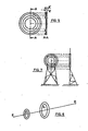
- The group of crowns of dielectric materials (one or more) arranged in the Fresnel I zones of a certain plane, is kept jointed by knowh mechanical means and is secured to its supporting base through posts, masts or any other supporting means conventionally used to keep objects at a level and in an orientation required. Figure 7 is a schematic representation of one of said supporting means, without any limitative character, and given as a simple illustrative example.
- By properly chosing the pahse variations obtained with the present process in all the Fresnel zones, so that at the outlet face the exiting waves of all the Fresnel zones result in the same phase, the maximum energy gain is obtained in the receiver. In one of the embodiments of the present process, a substantial increa se in the gain is obtained inverting the phases of the waves passing through different even Fresne zones, so that their contrtbutions to the field formation change the sign, being negative, and so they cooperate now with the odd zones to increase the value of the received field. As the phase variations depart from the inversion, the effects in the gain along ER become smaller. According to another embodiment of this process dielectric bodies with different thicknesses are inserted in various Fresnel zones, which, properly selected, nullify or drastically reduce an interfering signal arriving in a known direction.
- The same group of crowns resulting from the application of the described process can be used for various radioelectric channels E1R1, E2R2, etc. simultaneously when their axes cross in the centre of the group of crowns. As a non limiting example of an embodiment of the described process, in this particular case, is the production of a multiple antenna with a high gain, formed by a single group of dielectric crown and various coil antennas properly arranged in relation with the crowns, that can be used for the reception of the signals simultaneously from various television satellites.
- The passive process for the variation of the phases of the Fresnel zones is further a process by means of which the phases of every Fresnel zone are separately changed, and by selecting properly said variations it is possible to obtain the required purpose. It substantially consists in the introduction of dielectric bodies, transparent to the electromagnetic waves, which cover each Fresnel zone and having thicknesses suitable to obtain in every point the required phase change. Even if the size of these bodies is non exactly matched with the covered zones, for instance using polygonal crowns, the effect attained with the present process will be almost the same as that with crowns having the same size as the corresponding Fresnel zones.
Claims (9)
Applications Claiming Priority (2)
| Application Number | Priority Date | Filing Date | Title |
|---|---|---|---|
| ES541003A ES8700891A1 (en) | 1985-03-06 | 1985-03-06 | A passive process for the variation of the phases in the fresnel zones. |
| ES541003 | 1985-03-06 |
Publications (2)
| Publication Number | Publication Date |
|---|---|
| EP0194583A2 true EP0194583A2 (en) | 1986-09-17 |
| EP0194583A3 EP0194583A3 (en) | 1987-10-14 |
Family
ID=8488802
Family Applications (1)
| Application Number | Title | Priority Date | Filing Date |
|---|---|---|---|
| EP86102937A Withdrawn EP0194583A3 (en) | 1985-03-06 | 1986-03-06 | A passive process for the variation of the phases in the fresnel zones |
Country Status (3)
| Country | Link |
|---|---|
| EP (1) | EP0194583A3 (en) |
| ES (1) | ES8700891A1 (en) |
| PT (1) | PT82146A (en) |
Cited By (1)
| Publication number | Priority date | Publication date | Assignee | Title |
|---|---|---|---|---|
| FR2736470A1 (en) * | 1990-11-13 | 1997-01-10 | Bony Gerard | Microwave frequency antenna design method e.g. for radar - having cavity buried radiating surface with thick slab upper radome section and using Fourier transforms and Fresnel equations to determine antenna characteristics |
Citations (3)
| Publication number | Priority date | Publication date | Assignee | Title |
|---|---|---|---|---|
| US3189907A (en) * | 1961-08-11 | 1965-06-15 | Lylnan F Van Buskirk | Zone plate radio transmission system |
| US3495265A (en) * | 1965-08-11 | 1970-02-10 | Bell Telephone Labor Inc | Dielectric clutter fence |
| US4342033A (en) * | 1976-10-15 | 1982-07-27 | Camargo Luiz M V De | Wave action device for radio frequencies |
-
1985
- 1985-03-06 ES ES541003A patent/ES8700891A1/en not_active Expired
-
1986
- 1986-03-05 PT PT82146A patent/PT82146A/en not_active Application Discontinuation
- 1986-03-06 EP EP86102937A patent/EP0194583A3/en not_active Withdrawn
Patent Citations (3)
| Publication number | Priority date | Publication date | Assignee | Title |
|---|---|---|---|---|
| US3189907A (en) * | 1961-08-11 | 1965-06-15 | Lylnan F Van Buskirk | Zone plate radio transmission system |
| US3495265A (en) * | 1965-08-11 | 1970-02-10 | Bell Telephone Labor Inc | Dielectric clutter fence |
| US4342033A (en) * | 1976-10-15 | 1982-07-27 | Camargo Luiz M V De | Wave action device for radio frequencies |
Non-Patent Citations (4)
| Title |
|---|
| MICROWAVES, November 1979, pages 78-80, Hayden Publishing Co., Rochelle Park, US; M.J. LAZARUS: "Fresnel-zone plate aids low-cost Doppler design" * |
| REVIEW OF THE ELECTRICAL COMMUNICATION LABORATORY, vol. 14, nos. 1-2, January-February 1966, pages 53-72, Musashino, Tokyo, JP; M. TAKADA et al.: "Diffractor grating as a new microwave passive repeater" * |
| TELECOMMUNICATIONS & RADIO ENGINEERING, vol. 34/35, no. 5, May 1980, pages 28-32, Scripta Publishing Co., Silver Spring, US; I.L. NEPOMNYASHCHIY et al.: "An antenna director in the form of a flat polygonal screen" * |
| TELECOMMUNICATIONS AND RADIO ENGINEERING, vol. 34/35, no. 2, February 1980, pages 23-27, Scripta Publishing Co., Silver Spring, US; Y.M. MEL'NIKOV et al.: "Interference screening of radio relay antennas" * |
Cited By (1)
| Publication number | Priority date | Publication date | Assignee | Title |
|---|---|---|---|---|
| FR2736470A1 (en) * | 1990-11-13 | 1997-01-10 | Bony Gerard | Microwave frequency antenna design method e.g. for radar - having cavity buried radiating surface with thick slab upper radome section and using Fourier transforms and Fresnel equations to determine antenna characteristics |
Also Published As
| Publication number | Publication date |
|---|---|
| EP0194583A3 (en) | 1987-10-14 |
| ES8700891A1 (en) | 1986-12-01 |
| ES541003A0 (en) | 1986-12-01 |
| PT82146A (en) | 1986-09-16 |
Similar Documents
| Publication | Publication Date | Title |
|---|---|---|
| Kock | Metallic delay lenses | |
| US4395685A (en) | Waveguide junction for producing circularly polarized signal | |
| CA2037906A1 (en) | Cellular radiotelephone communications system | |
| Park et al. | A photonic bandgap (PBG) structure for guiding and suppressing surface waves in millimeter-wave antennas | |
| US2985880A (en) | Dielectric bodies for transmission of electromagnetic waves | |
| US2764757A (en) | Metallic lens antennas | |
| US2579324A (en) | Metallic structure for delaying propagated waves | |
| US3852762A (en) | Scanning lens antenna | |
| GB1227687A (en) | ||
| US2736894A (en) | Directive antenna systems | |
| AU567441B2 (en) | Continuous ferrite aperture for electronic scanning antennas | |
| RU2099834C1 (en) | Variable-index spherical dielectric lens | |
| US3604010A (en) | Antenna array system for generating shaped beams for guidance during aircraft landing | |
| GB1390635A (en) | Antennae with adjustable aperture | |
| US3553692A (en) | Antenna arrays having phase and amplitude control | |
| EP0194583A2 (en) | A passive process for the variation of the phases in the fresnel zones | |
| CA1186406A (en) | Dipole array lens antenna | |
| US4112431A (en) | Radiators for microwave aerials | |
| US3202997A (en) | Scanning corner array antenna | |
| CN116014454B (en) | Low sidelobe high XPD millimeter wave gap waveguide slot array antenna | |
| US11870148B2 (en) | Planar metal Fresnel millimeter-wave lens | |
| DE3801301A1 (en) | Fresnel zone plate (Fresnel lens) as a reflector for a microwave transmitting/receiving antenna | |
| GB1433022A (en) | Directive antenna arrays | |
| Hollis et al. | A Luneberg lens scanning system | |
| US2959784A (en) | Scanning antenna system |
Legal Events
| Date | Code | Title | Description |
|---|---|---|---|
| PUAI | Public reference made under article 153(3) epc to a published international application that has entered the european phase |
Free format text: ORIGINAL CODE: 0009012 |
|
| AK | Designated contracting states |
Kind code of ref document: A2 Designated state(s): AT BE CH DE FR GB IT LI LU NL SE |
|
| PUAL | Search report despatched |
Free format text: ORIGINAL CODE: 0009013 |
|
| AK | Designated contracting states |
Kind code of ref document: A3 Designated state(s): AT BE CH DE FR GB IT LI LU NL SE |
|
| 17P | Request for examination filed |
Effective date: 19880331 |
|
| 17Q | First examination report despatched |
Effective date: 19890831 |
|
| STAA | Information on the status of an ep patent application or granted ep patent |
Free format text: STATUS: THE APPLICATION IS DEEMED TO BE WITHDRAWN |
|
| 18D | Application deemed to be withdrawn |
Effective date: 19900111 |
|
| RIN1 | Information on inventor provided before grant (corrected) |
Inventor name: GOMEZ MOLI, MARIA ELENA |