EP0194225B1 - Current transformer for direct and alternating current - Google Patents
Current transformer for direct and alternating current Download PDFInfo
- Publication number
- EP0194225B1 EP0194225B1 EP86810018A EP86810018A EP0194225B1 EP 0194225 B1 EP0194225 B1 EP 0194225B1 EP 86810018 A EP86810018 A EP 86810018A EP 86810018 A EP86810018 A EP 86810018A EP 0194225 B1 EP0194225 B1 EP 0194225B1
- Authority
- EP
- European Patent Office
- Prior art keywords
- amplifier
- core
- air gap
- winding
- magnetic field
- Prior art date
- Legal status (The legal status is an assumption and is not a legal conclusion. Google has not performed a legal analysis and makes no representation as to the accuracy of the status listed.)
- Expired
Links
Images
Classifications
-
- G—PHYSICS
- G01—MEASURING; TESTING
- G01R—MEASURING ELECTRIC VARIABLES; MEASURING MAGNETIC VARIABLES
- G01R15/00—Details of measuring arrangements of the types provided for in groups G01R17/00 - G01R29/00, G01R33/00 - G01R33/26 or G01R35/00
- G01R15/14—Adaptations providing voltage or current isolation, e.g. for high-voltage or high-current networks
- G01R15/20—Adaptations providing voltage or current isolation, e.g. for high-voltage or high-current networks using galvano-magnetic devices, e.g. Hall-effect devices, i.e. measuring a magnetic field via the interaction between a current and a magnetic field, e.g. magneto resistive or Hall effect devices
- G01R15/207—Constructional details independent of the type of device used
-
- H—ELECTRICITY
- H01—ELECTRIC ELEMENTS
- H01F—MAGNETS; INDUCTANCES; TRANSFORMERS; SELECTION OF MATERIALS FOR THEIR MAGNETIC PROPERTIES
- H01F38/00—Adaptations of transformers or inductances for specific applications or functions
- H01F38/20—Instruments transformers
- H01F38/22—Instruments transformers for single phase ac
- H01F38/28—Current transformers
Definitions
- Current transformers are also known, for example according to document JP-A-58 216 412, the basic element of which is formed for a magnetic core A and by a winding.
- a core A with an air gap and with high permeability, has been added to a core B with low permeability and having an air gap and whose magnetic saturation nese produces only for currents much stronger than those causing the saturation of the core A.
- the problem of the frequency is not approached.
- the present invention aims to improve the dynamic performance of intensity transformers of the aforementioned type. This result is obtained thanks to the fact that the magnetic circuit comprises a second ferromagnetic core without air gap, this second core being magnetically coupled to the first core by said windings.
- the senor comprises a ferromagnetic core 1 of rectangular shape.
- This core 1 has an air gap 2 in which is disposed an element 3 sensitive to the magnetic field prevailing in this air gap.
- This element 3 can in particular consist of a HALL effect cell.
- This cell is powered by a current supplied by two batteries 4 and 5 connected in series and the connection point of which is connected to earth.
- When cell 3 is placed in a magnetic field transverse to its plane, it gives rise to a voltage between two electrodes 6 and 7 arranged perpendicularly to the current flowing through it.
- This voltage is applied to an amplifier 8 whose gain is very high and whose output feeds a secondary winding 9 which surrounds the core 1.
- this winding 9 is shown on a branch different from that containing the cell 3 for more for clarity, but in principle, this secondary winding is arranged on the branch in which the cell 3 is located.
- the amplifier circulates in the winding 9 a current which must cancel the magnetic field producing said voltage and due to the passage of current in a primary winding 10 which is most often consisting of a simple rectilinear conductor.
- the current flowing in the secondary winding 9 is measured by an ammeter A, which gives an indication proportional to the current flowing in the primary winding 10.
- FIG. 3 Three operating regimes are to be discerned. They are shown diagrammatically in FIG. 3.
- the amplifier imposes the fundamental relation of perfect transformers, extended even for direct currents.
- the flux in the magnetic core is zero, the ampere-turns traversing the secondary winding are equal to the ampere-turns of the primary winding.
- the area f1 to f2 is due to the gain-frequency transfer characteristic of the amplifier.
- the area f2 to f3 is characterized by the weakening of the secondary signal at low frequencies due to the presence of the air gap.
- the assembly behaves like a current transformer.
- Fig. 2 schematically illustrates an embodiment of the sensor allowing much higher dynamic performance.
- the sensor comprises two magnetic cores 11 and 12 of annular shape and arranged side by side.
- the core 11 has an air gap 13 in which is placed a HALL effect cell, such as element 3 of FIG. 1. This cell is supplied by the batteries 4 and 5 and its output drives an amplifier 8 with high gain.
- the core 12 is distant from the core 11 by a sufficient value d to prevent it from magnetically short-circuiting the magnetic field in the air gap 2.
- the ferromagnetic core 12 has no air gap and is dimensioned to ensure a correct response from a frequency below f1 and up to a frequency fx2 (Fig. 4).
- the pole P2 corresponding to the lower cut-off frequency of the ferromagnetic core 12 and the windings, is located at a frequency lower than pole P1, corresponding to the cut-off frequency of the amplifier.
- the cut-off frequency of the assembly is linear from f0 to fx2 which is higher than the frequency fx1 of the known device.
- the ferromagnetic cores do not necessarily have to be annular in shape or be arranged side by side. Alternatively, one of the cores could be arranged inside the other, which gives a compact construction. It is also possible to provide that the magnetic circuit 12 may consist of two ferromagnetic cores arranged coaxially and on either side of the core 11 with air gap.
Landscapes
- Engineering & Computer Science (AREA)
- Power Engineering (AREA)
- Physics & Mathematics (AREA)
- General Physics & Mathematics (AREA)
- Measuring Instrument Details And Bridges, And Automatic Balancing Devices (AREA)
- Transformers For Measuring Instruments (AREA)
- Hybrid Cells (AREA)
Description
On connaît déjà du document DE-A-2 224 618 des capteurs d'intensité pour courants continus et alternatifs, comprenant un circuit magnétique constitué par une carcasse possédant un entrefer et portant deux enroulements, un élément à effet HALL étant sensible au champ magnétique régnant dans l'entrefer, cet élément fournissant un signal électrique dépendant du champ magnétique, un amplificateur contrôlé par ledit signal, cet amplificateur alimentant l'un des deux enroulements dans un sens tel qu'il tende à annuler le champ magnétique qui donne naissance audit signal électrique, un dispositif de mesure de courant étant branché en série avec l'enroulement alimenté par l'amplificateur.Document DE-A-2 224 618 already knows intensity sensors for direct and alternating currents, comprising a magnetic circuit constituted by a carcass having an air gap and carrying two windings, a HALL effect element being sensitive to the prevailing magnetic field. in the air gap, this element providing an electric signal dependent on the magnetic field, an amplifier controlled by said signal, this amplifier supplying one of the two windings in a direction such that it tends to cancel the magnetic field which gives rise to said signal electric, a current measurement device being connected in series with the winding supplied by the amplifier.
On connaît egalement des transformateurs d'intensité, par exemple selon le document JP-A-58 216 412, dont l'élément de base est constitué pour un noyau magnétique A et par un enroulement. Pour permettre la mesure d'un courant alternatif de faible intensité et jusqu'a une très forte intensité, on a ajouté an noyau A, saus entrefer et à haute permeabilité, un noyau B à faible perméabilité et présentant un entrefer et dont la saturation magnétique nese produit que pour des courants beaucoup plus fort que ceux provoquant la saturation du noyau A. Dans ce document, le problème de la fréquence n'est pas abordé.Current transformers are also known, for example according to document JP-A-58 216 412, the basic element of which is formed for a magnetic core A and by a winding. To allow the measurement of an alternating current of low intensity and up to a very high intensity, a core A, with an air gap and with high permeability, has been added to a core B with low permeability and having an air gap and whose magnetic saturation nese produces only for currents much stronger than those causing the saturation of the core A. In this document, the problem of the frequency is not approached.
Les capteurs de ce genre donnent entière satisfaction pour la mesure des courants continus ainsi que pour les courants alternatifs de fréquence relativement basse. Toutefois lorsque la fréquence des courants alternatifs augmente, la réponse du système diminue principalement en raison du flux de fuite dû à l'entrefer, d'une part et en fonction de la réponse en fréquence de l'amplificateur d'autre part.Sensors of this kind give complete satisfaction for the measurement of direct currents as well as for alternating currents of relatively low frequency. However when the frequency of the alternating currents increases, the response of the system decreases mainly due to the leakage flux due to the air gap, on the one hand and according to the frequency response of the amplifier on the other hand.
La présente invention a pour but d'améliorer les performances dynamiques des transformateurs d'intensité du type précité. Ce résultat est obtenu grâce au fait que le circuit magnétique comprend un deuxième noyau ferromagnétique dépourvu d'entrefer, ce deuxième noyau étant couplé magnétiquement au premier noyau par lesdits enroulements.The present invention aims to improve the dynamic performance of intensity transformers of the aforementioned type. This result is obtained thanks to the fact that the magnetic circuit comprises a second ferromagnetic core without air gap, this second core being magnetically coupled to the first core by said windings.
Le dessin annexé montre un dispositif connu et, à titre d'exemple, une forme d'exécution du dispositif objet de l'invention.
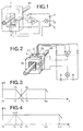
- La fig. 1 représente le dispositif connu.
- La fig. 2 représente ladite forme d'exécution.
- La fig. 3 est un diagramme de la courbe de réponse du transformateur de la fig. 1.
- La fig. 4 est un diagramme de la courbe de réponse du transformateur de la fig. 2.
- Fig. 1 shows the known device.
- Fig. 2 shows said embodiment.
- Fig. 3 is a diagram of the response curve of the transformer in FIG. 1.
- Fig. 4 is a diagram of the response curve of the transformer in FIG. 2.
Dans le dispositif connu, illustré à la fig. 1, le capteur comprend un noyau 1 ferromagnétique de forme rectangulaire. Ce noyau 1 présente un entrefer 2 dans lequel est disposé un élément 3 sensible au champ magnétique régnant dans cet entrefer. Cet élément 3 peut être notamment constitué par une cellule à effet HALL. Cette cellule est alimentée par un courant fourni par deux batteries 4 et 5 montées en série et dont le point de connexion est relié à la terre. Lorsque la cellule 3 est placée dans un champ magnétique transversal à son plan, elle donne naissance à une tension entre deux électrodes 6 et 7 disposées perpendiculairement par rapport au courant qui la traverse. Cette tension est appliquée à un amplificateur 8 dont le gain est très élevé et dont la sortie alimente un enroulement secondaire 9 qui entoure le noyau 1. Au dessin, on a représenté cet enroulement 9 sur une branche différente de celle contenant la cellule 3 pour plus de clarté, mais en principe, cet enroulement secondaire est disposé sur la branche dans laquelle se trouve la cellule 3.In the known device, illustrated in FIG. 1, the sensor comprises a ferromagnetic core 1 of rectangular shape. This core 1 has an
Dès qu'un champ magnétique agit sur la cellule 3, l'amplificateur fait circuler dans l'enroulement 9 un courant qui doit en annuler le champ magnétique produisant ladite tension et dû au passage du courant dans un enroulement primaire 10 qui est le plus souvent constitué par un simple conducteur rectiligne. Le courant circulant dans l'enroulement secondaire 9 est mesuré par un ampèremètre A, lequel donne une indication proportionnelle au courant passant dans l'enroulement primaire 10.As soon as a magnetic field acts on the
Trois régimes de fonctionnement sont à discerner. Ils sont schématisés par la fig. 3.Three operating regimes are to be discerned. They are shown diagrammatically in FIG. 3.
a) Régime statique ou faiblement dynamique, de fO à f1 :a) Static or weakly dynamic regime, from fO to f1:
Dans ce cas l'amplificateur impose la relation fondamentale des transformateurs parfaits, étendue même pour les courants continus. le flux dans le noyau magnétique est nul, les ampère-tours parcourant l'enroulement secondaire sont égaux aux ampère-tours de l'enroulement primaire.In this case the amplifier imposes the fundamental relation of perfect transformers, extended even for direct currents. the flux in the magnetic core is zero, the ampere-turns traversing the secondary winding are equal to the ampere-turns of the primary winding.
b) Régime de transition, de f1 à f3, délimité par les pôles P1 à P2:b) Transition regime, from f1 to f3, delimited by the poles P1 to P2:
La zone f1 à f2 est dûe à la caractéristique de transfert gainfréquence de l'amplificateur. La zone f2 à f3 est caractérisée par l'affaiblissement du signal secondaire aux basses fréquences dû à la présence de l'entrefer.The area f1 to f2 is due to the gain-frequency transfer characteristic of the amplifier. The area f2 to f3 is characterized by the weakening of the secondary signal at low frequencies due to the presence of the air gap.
c) Régime dynamique de f3 à fx1:c) Dynamic regime from f3 to fx1:
L'ensemble se comporte comme un transformateur de courant.The assembly behaves like a current transformer.
La fig. 2 illustre schématiquement une forme d'exécution du capteur permettant des performances dynamiques beaucoup plus élevées. A cet effet, le capteur comprend deux noyaux magnétiques 11 et 12 de forme annulaire et disposés côte à côte. Le noyau 11 présente un entrefer 13 dans lequel est placé une cellule à effet HALL, telle que l'élément 3 de la figure 1. Cette cellule est alimentée par les batteries 4 et 5 et sa sortie attaque un amplificateur 8 à gain élevé. Le noyau 12 est éloigné du noyau 11 d'une valeur suffisante d pour éviter qu'il ne court-circuite magnétiquement le champ magnétique dans l'entrefer 2.Fig. 2 schematically illustrates an embodiment of the sensor allowing much higher dynamic performance. To this end, the sensor comprises two
Le noyau ferromagnétique 12 ne comporte pas d'entrefer et il est dimensionné pour assurer une réponse correcte à partir d'une fréquence inférieure à f1 et jusqu'à une fréquence fx2 (Fig. 4).The
En résumé, le pôle P2, correspondant à la fréquence de coupure inférieure du noyau ferromagnétique 12 et des enroulements, est situé à une fréquence plus basse que le pôle P1, correspondant à la fréquence de coupure de l'amplificateur. Ainsi, la fréquence de coupure de l'ensemble est linéaire de f0 à fx2 qui est supérieure à la fréquence fx1 du dispositif connu.In summary, the pole P2, corresponding to the lower cut-off frequency of the
On peut, bien entendu, prévoir de nombreuses variantes d'exécution. En effet, les noyaux ferromagnétiques ne doivent pas nécessairement être de forme annulaire ni être disposés côte à côte. Selon une variante, un des noyaux pourrait être disposé à l'intérieur de l'autre, ce qui donne une construction compacte. Il est également possible de prévoir que le circuit magnétique 12 peut être constitué de deux noyaux ferromagnétiques disposés coaxialement et de part et d'autre du noyau 11 avec entrefer.We can, of course, provide many alternative embodiments. Indeed, the ferromagnetic cores do not necessarily have to be annular in shape or be arranged side by side. Alternatively, one of the cores could be arranged inside the other, which gives a compact construction. It is also possible to provide that the
Claims (3)
Applications Claiming Priority (2)
| Application Number | Priority Date | Filing Date | Title |
|---|---|---|---|
| CH499/85 | 1985-02-05 | ||
| CH499/85A CH662000A5 (en) | 1985-02-05 | 1985-02-05 | CURRENT TRANSFORMER FOR DIRECT AND ALTERNATING CURRENT. |
Publications (2)
| Publication Number | Publication Date |
|---|---|
| EP0194225A1 EP0194225A1 (en) | 1986-09-10 |
| EP0194225B1 true EP0194225B1 (en) | 1989-09-27 |
Family
ID=4188404
Family Applications (1)
| Application Number | Title | Priority Date | Filing Date |
|---|---|---|---|
| EP86810018A Expired EP0194225B1 (en) | 1985-02-05 | 1986-01-17 | Current transformer for direct and alternating current |
Country Status (5)
| Country | Link |
|---|---|
| US (1) | US4682101A (en) |
| EP (1) | EP0194225B1 (en) |
| JP (1) | JPS61245511A (en) |
| CH (1) | CH662000A5 (en) |
| DE (1) | DE3665957D1 (en) |
Cited By (3)
| Publication number | Priority date | Publication date | Assignee | Title |
|---|---|---|---|---|
| DE102007013634A1 (en) | 2007-03-19 | 2008-09-25 | Balfour Beatty Plc | Device for measuring a direct current component of a current flowing in conductors of alternating current paths superimposed by an alternating current component |
| DE102012216554A1 (en) | 2012-09-17 | 2014-03-20 | Siemens Aktiengesellschaft | Direct current measurement device for measurement system for measuring direct current component, has alternating current compensation winding, and primary core with alternating current to direct current compensation winding and pick-up coil |
| US11391761B2 (en) | 2018-01-30 | 2022-07-19 | Siemens Energy Global GmbH & Co. KG | Current converter |
Families Citing this family (36)
| Publication number | Priority date | Publication date | Assignee | Title |
|---|---|---|---|---|
| US4862040A (en) * | 1987-03-18 | 1989-08-29 | Nilssen Ole K | Frequency-modulated inverter-type ballast |
| US4851739A (en) * | 1987-06-09 | 1989-07-25 | Nilssen Ole K | Controlled-frequency series-resonant ballast |
| FR2619925B1 (en) * | 1987-08-26 | 1989-12-22 | Bruni Olivier | STRONG CURRENT MEASURING DEVICE |
| US4823075A (en) * | 1987-10-13 | 1989-04-18 | General Electric Company | Current sensor using hall-effect device with feedback |
| FR2624617B1 (en) * | 1987-12-11 | 1990-05-11 | Europ Agence Spatiale | MAGNETICALLY COUPLED ELECTRIC CURRENT MEASURING APPARATUS |
| FR2635224B1 (en) * | 1988-08-05 | 1990-11-02 | Petercem Sa | INTENSITY TRANSFORMER FOR DIRECT, ALTERNATIVE OR PULSED CURRENTS |
| FR2645650B1 (en) * | 1989-04-06 | 1991-09-27 | Merlin Gerin | SYSTEM FOR CONTROLLING THE ISOLATION OF A DIRECT CURRENT NETWORK |
| CH679527A5 (en) * | 1989-04-13 | 1992-02-28 | Lem Liaisons Electron Mec | |
| DE3929452A1 (en) * | 1989-09-05 | 1991-03-07 | Asea Brown Boveri | Potential-less current measurer suitable for monitoring and protection - comprises magnetic field ring sensor with substrate having central opening for current conductor |
| US5103163A (en) * | 1990-10-17 | 1992-04-07 | California Institute Of Technology | Current transducer |
| US5180970A (en) * | 1992-02-10 | 1993-01-19 | Honeywell Inc. | Mechanically adjustable current sensor and method for making same |
| FR2693831B1 (en) * | 1992-07-15 | 1994-10-14 | Abb Control Sa | Current-controlled transformer for direct, alternating or pulsed currents. |
| US5493211A (en) * | 1993-07-15 | 1996-02-20 | Tektronix, Inc. | Current probe |
| US5450000A (en) * | 1994-02-14 | 1995-09-12 | Unity Power Corporation | Using hall device for controlling current in a switchmode circuit |
| US5479095A (en) * | 1994-06-30 | 1995-12-26 | Power Corporation Of America | Method and apparatus for measurement of AC and DC electrical current |
| US5517154A (en) * | 1995-01-13 | 1996-05-14 | Tektronix, Inc. | Split-path linear isolation circuit apparatus and method |
| CH690464A5 (en) * | 1995-02-23 | 2000-09-15 | Lem Liaisons Electron Mec | inductive measurement device for measurement of AC components superimposed on a high DC current. |
| JPH08273952A (en) * | 1995-03-31 | 1996-10-18 | Ikuro Moriwaki | Plane current detector |
| ES2113808B1 (en) * | 1995-09-29 | 1999-01-16 | Univ Valencia | CURRENT SENSOR OF VERY LOW IMPEDANCE AND HIGH STABILITY. |
| US5850114A (en) * | 1996-12-23 | 1998-12-15 | Froidevaux; Jean-Claude | Device for improving the quality of audio and/or video signals |
| US5995347A (en) * | 1997-05-09 | 1999-11-30 | Texas Instruments Incorporated | Method and apparatus for multi-function electronic motor protection |
| EP1058278B1 (en) | 1999-06-04 | 2012-02-29 | Liaisons Electroniques-Mecaniques Lem S.A. | Wound magnetic circuit |
| US6445171B2 (en) | 1999-10-29 | 2002-09-03 | Honeywell Inc. | Closed-loop magnetoresistive current sensor system having active offset nulling |
| US6459349B1 (en) | 2000-03-06 | 2002-10-01 | General Electric Company | Circuit breaker comprising a current transformer with a partial air gap |
| DE10145415A1 (en) * | 2001-09-14 | 2003-04-03 | Aloys Wobben | Instrument transformer, in particular for an inverter of a wind energy plant |
| EP1450176A1 (en) * | 2003-02-21 | 2004-08-25 | Liaisons Electroniques-Mecaniques Lem S.A. | Magnetic field sensor and electrical current sensor therewith |
| JP4628987B2 (en) * | 2006-04-10 | 2011-02-09 | 矢崎総業株式会社 | Current sensor with temperature detection function |
| US7309980B2 (en) * | 2006-05-08 | 2007-12-18 | Tektronix, Inc. | Current sensing circuit for use in a current measurement probe |
| DE102008036582A1 (en) * | 2008-08-06 | 2010-02-11 | Reo Inductive Components Ag | Kompensationsstromumwandler |
| CN102116786A (en) * | 2010-12-31 | 2011-07-06 | 广东电网公司电力科学研究院 | Neutral point direct current online measurement device for transformer |
| CN102495321B (en) * | 2011-12-21 | 2014-04-16 | 中国科学院上海微系统与信息技术研究所 | Method for generating and identifying non-linear signal in semiconductor non-linear oscillation system |
| EP2682762A1 (en) * | 2012-07-06 | 2014-01-08 | Senis AG | Current transducer for measuring an electrical current, magnetic transducer and current leakage detection system and method |
| EP2690450B1 (en) | 2012-07-27 | 2014-07-09 | ABB Technology AG | A device for measuring the direct component of alternating current |
| RU2644574C1 (en) * | 2016-10-18 | 2018-02-13 | Федеральное государственное автономное образовательное учреждение высшего образования "Национальный исследовательский Томский политехнический университет" | Device for measuring variable currents of high-voltage electric transmission line |
| JP6508163B2 (en) | 2016-10-31 | 2019-05-08 | 横河電機株式会社 | Current measurement device |
| EP3907511A3 (en) | 2020-05-08 | 2022-03-16 | Hamilton Sundstrand Corporation | Radiation hardened magnetic current sensor |
Family Cites Families (4)
| Publication number | Priority date | Publication date | Assignee | Title |
|---|---|---|---|---|
| US3525041A (en) * | 1966-08-08 | 1970-08-18 | Tektronix Inc | Magnetic field measuring method and device effective over a wide frequency range |
| DE2224618A1 (en) * | 1972-03-09 | 1973-09-20 | Lem Liaisons Electron Mec | ELECTRONIC CURRENT CONVERTER FOR DC AND AC CURRENT |
| US4482862A (en) * | 1982-06-10 | 1984-11-13 | The Charles Stark Draper Laboratory, Inc. | Current sensor |
| JPH0624208B2 (en) * | 1982-07-29 | 1994-03-30 | 日本電気株式会社 | Semiconductor device |
-
1985
- 1985-02-05 CH CH499/85A patent/CH662000A5/en not_active IP Right Cessation
-
1986
- 1986-01-17 DE DE8686810018T patent/DE3665957D1/en not_active Expired
- 1986-01-17 EP EP86810018A patent/EP0194225B1/en not_active Expired
- 1986-01-24 US US06/821,976 patent/US4682101A/en not_active Expired - Lifetime
- 1986-02-04 JP JP61022811A patent/JPS61245511A/en active Pending
Cited By (4)
| Publication number | Priority date | Publication date | Assignee | Title |
|---|---|---|---|---|
| DE102007013634A1 (en) | 2007-03-19 | 2008-09-25 | Balfour Beatty Plc | Device for measuring a direct current component of a current flowing in conductors of alternating current paths superimposed by an alternating current component |
| DE202007019127U1 (en) | 2007-03-19 | 2010-11-04 | Balfour Beatty Plc | Device for measuring a direct current component of a current flowing in conductors of alternating current paths superimposed by an alternating current component |
| DE102012216554A1 (en) | 2012-09-17 | 2014-03-20 | Siemens Aktiengesellschaft | Direct current measurement device for measurement system for measuring direct current component, has alternating current compensation winding, and primary core with alternating current to direct current compensation winding and pick-up coil |
| US11391761B2 (en) | 2018-01-30 | 2022-07-19 | Siemens Energy Global GmbH & Co. KG | Current converter |
Also Published As
| Publication number | Publication date |
|---|---|
| US4682101A (en) | 1987-07-21 |
| CH662000A5 (en) | 1987-08-31 |
| JPS61245511A (en) | 1986-10-31 |
| EP0194225A1 (en) | 1986-09-10 |
| DE3665957D1 (en) | 1989-11-02 |
Similar Documents
| Publication | Publication Date | Title |
|---|---|---|
| EP0194225B1 (en) | Current transformer for direct and alternating current | |
| EP0356171A2 (en) | Direct-coupled fluxgate current sensor and sensing method using the same | |
| CA1182537A (en) | Dynamic current sensor | |
| US5523677A (en) | DC current sensor | |
| EP0392439A1 (en) | Current transformer for measuring a variable electrical current | |
| FR2887634A1 (en) | DIFFERENTIAL CURRENT MEASURING DEVICE, TRIGGER MODULE COMPRISING SUCH A MEASURING DEVICE AND CUTTING DEVICE HAVING SUCH A MODULE | |
| FR2542130A1 (en) | CURRENT MEASUREMENT TRANSFORMER | |
| FR2622017A1 (en) | ELECTRIC CURRENT SENSOR DEVICE | |
| EP1498739B1 (en) | Current sensor having a magnetic core with airgap and power supply circuit provided with such sensors | |
| FR2828740A1 (en) | METHOD FOR STABILIZING A MAGNETOMETER SIGNAL, AND STABILIZED MAGNETOMETERS | |
| EP1084417B1 (en) | Electric current sensor with wide passband | |
| FR2859022A1 (en) | Device for measuring a current of high intensity passing through a wire, includes a loop surrounding the magnetic sensor, with the loop being a closed loop and therefore in short-circuit | |
| FR2472758A1 (en) | METHOD FOR MEASURING THE SPECIFIC CAPACITY OF A CABLE, ASSEMBLY AND DEVICE FOR CARRYING OUT SAID METHOD | |
| EP0023456B1 (en) | Method and apparatus using eddy currents for nondestructive testing for the detection of carburised zones | |
| EP0622635A1 (en) | Current sensor for alternating current | |
| FR2460484A1 (en) | MAGNETOELECTRIC DISPLACEMENT SENSOR OF A MOVING PIECE, AND DETECTION SYSTEM PROVIDED WITH SUCH A SENSOR | |
| FR2983966A1 (en) | Device for measuring electric current crossing surface for measuring leakage currents for telecommunication systems, has low pass filter that is utilized for extracting coil current signal that is representative of current | |
| GB1475162A (en) | Meidensha kk device for and method of detecting short circuit in a transfor mer winding | |
| EP0354079A1 (en) | Current transformer for continuous, alternative or pulsed current | |
| JPH073345Y2 (en) | DC current detector | |
| FR2744529A1 (en) | Measurement of low value continuous current in conductor | |
| FR2687478A1 (en) | Device for measuring a magnetic field gradient with minimal errors due to sensitivity and misalignment | |
| BE650557A (en) | ||
| JPH10253665A (en) | Current detector | |
| JPH0510980A (en) | Current detection method |
Legal Events
| Date | Code | Title | Description |
|---|---|---|---|
| PUAI | Public reference made under article 153(3) epc to a published international application that has entered the european phase |
Free format text: ORIGINAL CODE: 0009012 |
|
| AK | Designated contracting states |
Kind code of ref document: A1 Designated state(s): DE FR GB IT |
|
| 17P | Request for examination filed |
Effective date: 19861217 |
|
| 17Q | First examination report despatched |
Effective date: 19880422 |
|
| GRAA | (expected) grant |
Free format text: ORIGINAL CODE: 0009210 |
|
| AK | Designated contracting states |
Kind code of ref document: B1 Designated state(s): DE FR GB IT |
|
| ITF | It: translation for a ep patent filed |
Owner name: JACOBACCI & PERANI S.P.A. |
|
| GBT | Gb: translation of ep patent filed (gb section 77(6)(a)/1977) | ||
| REF | Corresponds to: |
Ref document number: 3665957 Country of ref document: DE Date of ref document: 19891102 |
|
| PLBE | No opposition filed within time limit |
Free format text: ORIGINAL CODE: 0009261 |
|
| STAA | Information on the status of an ep patent application or granted ep patent |
Free format text: STATUS: NO OPPOSITION FILED WITHIN TIME LIMIT |
|
| 26N | No opposition filed | ||
| ITTA | It: last paid annual fee | ||
| PGFP | Annual fee paid to national office [announced via postgrant information from national office to epo] |
Ref country code: FR Payment date: 19931230 Year of fee payment: 9 |
|
| PGFP | Annual fee paid to national office [announced via postgrant information from national office to epo] |
Ref country code: GB Payment date: 19940110 Year of fee payment: 9 |
|
| PG25 | Lapsed in a contracting state [announced via postgrant information from national office to epo] |
Ref country code: GB Effective date: 19950117 |
|
| GBPC | Gb: european patent ceased through non-payment of renewal fee |
Effective date: 19950117 |
|
| PG25 | Lapsed in a contracting state [announced via postgrant information from national office to epo] |
Ref country code: FR Effective date: 19950929 |
|
| REG | Reference to a national code |
Ref country code: FR Ref legal event code: ST |
|
| PGFP | Annual fee paid to national office [announced via postgrant information from national office to epo] |
Ref country code: DE Payment date: 20050106 Year of fee payment: 20 |
|
| PG25 | Lapsed in a contracting state [announced via postgrant information from national office to epo] |
Ref country code: IT Free format text: LAPSE BECAUSE OF NON-PAYMENT OF DUE FEES;WARNING: LAPSES OF ITALIAN PATENTS WITH EFFECTIVE DATE BEFORE 2007 MAY HAVE OCCURRED AT ANY TIME BEFORE 2007. THE CORRECT EFFECTIVE DATE MAY BE DIFFERENT FROM THE ONE RECORDED. Effective date: 20050117 |