EP0193662B1 - Bauelemente - Google Patents
Bauelemente Download PDFInfo
- Publication number
- EP0193662B1 EP0193662B1 EP85301465A EP85301465A EP0193662B1 EP 0193662 B1 EP0193662 B1 EP 0193662B1 EP 85301465 A EP85301465 A EP 85301465A EP 85301465 A EP85301465 A EP 85301465A EP 0193662 B1 EP0193662 B1 EP 0193662B1
- Authority
- EP
- European Patent Office
- Prior art keywords
- edges
- module
- straight
- sheet
- modules
- Prior art date
- Legal status (The legal status is an assumption and is not a legal conclusion. Google has not performed a legal analysis and makes no representation as to the accuracy of the status listed.)
- Expired
Links
- 239000000463 material Substances 0.000 claims description 35
- 238000005452 bending Methods 0.000 claims description 19
- 238000000034 method Methods 0.000 claims description 18
- 238000005304 joining Methods 0.000 claims description 5
- 238000001746 injection moulding Methods 0.000 claims description 2
- 238000005266 casting Methods 0.000 claims 1
- 239000011248 coating agent Substances 0.000 claims 1
- 238000000576 coating method Methods 0.000 claims 1
- 239000007769 metal material Substances 0.000 claims 1
- 229910000831 Steel Inorganic materials 0.000 description 20
- 239000010959 steel Substances 0.000 description 20
- 238000010276 construction Methods 0.000 description 13
- 229910052751 metal Inorganic materials 0.000 description 9
- 239000002184 metal Substances 0.000 description 9
- 239000004744 fabric Substances 0.000 description 6
- 238000005253 cladding Methods 0.000 description 4
- 239000007787 solid Substances 0.000 description 4
- 230000015572 biosynthetic process Effects 0.000 description 3
- 238000005516 engineering process Methods 0.000 description 3
- 230000001788 irregular Effects 0.000 description 2
- 238000004519 manufacturing process Methods 0.000 description 2
- 230000000452 restraining effect Effects 0.000 description 2
- 238000003466 welding Methods 0.000 description 2
- 229910052782 aluminium Inorganic materials 0.000 description 1
- XAGFODPZIPBFFR-UHFFFAOYSA-N aluminium Chemical compound [Al] XAGFODPZIPBFFR-UHFFFAOYSA-N 0.000 description 1
- 238000004873 anchoring Methods 0.000 description 1
- 239000002131 composite material Substances 0.000 description 1
- 150000001875 compounds Chemical class 0.000 description 1
- 230000006835 compression Effects 0.000 description 1
- 238000007906 compression Methods 0.000 description 1
- 229910003460 diamond Inorganic materials 0.000 description 1
- 239000010432 diamond Substances 0.000 description 1
- 210000000959 ear middle Anatomy 0.000 description 1
- 238000009408 flooring Methods 0.000 description 1
- 239000012530 fluid Substances 0.000 description 1
- 239000011521 glass Substances 0.000 description 1
- 238000009434 installation Methods 0.000 description 1
- 238000000465 moulding Methods 0.000 description 1
- 239000004033 plastic Substances 0.000 description 1
- 239000002994 raw material Substances 0.000 description 1
- 230000000284 resting effect Effects 0.000 description 1
- 238000007493 shaping process Methods 0.000 description 1
Images


Classifications
-
- E—FIXED CONSTRUCTIONS
- E04—BUILDING
- E04C—STRUCTURAL ELEMENTS; BUILDING MATERIALS
- E04C2/00—Building elements of relatively thin form for the construction of parts of buildings, e.g. sheet materials, slabs, or panels
- E04C2/30—Building elements of relatively thin form for the construction of parts of buildings, e.g. sheet materials, slabs, or panels characterised by the shape or structure
- E04C2/32—Building elements of relatively thin form for the construction of parts of buildings, e.g. sheet materials, slabs, or panels characterised by the shape or structure formed of corrugated or otherwise indented sheet-like material; composed of such layers with or without layers of flat sheet-like material
- E04C2/328—Building elements of relatively thin form for the construction of parts of buildings, e.g. sheet materials, slabs, or panels characterised by the shape or structure formed of corrugated or otherwise indented sheet-like material; composed of such layers with or without layers of flat sheet-like material slightly bowed or folded panels not otherwise provided for
-
- E—FIXED CONSTRUCTIONS
- E04—BUILDING
- E04B—GENERAL BUILDING CONSTRUCTIONS; WALLS, e.g. PARTITIONS; ROOFS; FLOORS; CEILINGS; INSULATION OR OTHER PROTECTION OF BUILDINGS
- E04B1/00—Constructions in general; Structures which are not restricted either to walls, e.g. partitions, or floors or ceilings or roofs
- E04B1/32—Arched structures; Vaulted structures; Folded structures
- E04B1/3211—Structures with a vertical rotation axis or the like, e.g. semi-spherical structures
-
- E—FIXED CONSTRUCTIONS
- E04—BUILDING
- E04B—GENERAL BUILDING CONSTRUCTIONS; WALLS, e.g. PARTITIONS; ROOFS; FLOORS; CEILINGS; INSULATION OR OTHER PROTECTION OF BUILDINGS
- E04B1/00—Constructions in general; Structures which are not restricted either to walls, e.g. partitions, or floors or ceilings or roofs
- E04B1/32—Arched structures; Vaulted structures; Folded structures
- E04B2001/3223—Theorical polygonal geometry therefor
-
- E—FIXED CONSTRUCTIONS
- E04—BUILDING
- E04B—GENERAL BUILDING CONSTRUCTIONS; WALLS, e.g. PARTITIONS; ROOFS; FLOORS; CEILINGS; INSULATION OR OTHER PROTECTION OF BUILDINGS
- E04B1/00—Constructions in general; Structures which are not restricted either to walls, e.g. partitions, or floors or ceilings or roofs
- E04B1/32—Arched structures; Vaulted structures; Folded structures
- E04B2001/327—Arched structures; Vaulted structures; Folded structures comprised of a number of panels or blocs connected together forming a self-supporting structure
-
- Y—GENERAL TAGGING OF NEW TECHNOLOGICAL DEVELOPMENTS; GENERAL TAGGING OF CROSS-SECTIONAL TECHNOLOGIES SPANNING OVER SEVERAL SECTIONS OF THE IPC; TECHNICAL SUBJECTS COVERED BY FORMER USPC CROSS-REFERENCE ART COLLECTIONS [XRACs] AND DIGESTS
- Y10—TECHNICAL SUBJECTS COVERED BY FORMER USPC
- Y10S—TECHNICAL SUBJECTS COVERED BY FORMER USPC CROSS-REFERENCE ART COLLECTIONS [XRACs] AND DIGESTS
- Y10S52/00—Static structures, e.g. buildings
- Y10S52/10—Polyhedron
Definitions
- This invention relates to a complex, substantially polyhedral, three-dimensional modules for defining in conjunction with other, similar modules, space enclosing structures.
- U.S.-A-3495369 discloses a building element comprising a thin elongate shell of substantially constant thickness having an outer surface presenting rectilineal edges. At its front and rear ends the element comprises two flat portions or tympanums which are transversed longitudinal plan of symmetry element the contour of which is that of a curvialinear triangle.
- U.S.-A-3921349 shows a structural element obtained by folding of flat quadrilateral plate of rhombus or diamond form along its lon- gidiagonal thereby creating a dihedral angle which is enclosed by two identical triangular portions of the component, each triangular portion having free edges.
- To maintain the fold angle at a desired degree of transverse restraining member in the form of a tie-rod is secured to the apices of the triangular portions which lie outside the fold line.
- the folded quadrilateral plate member and the transverse restraining member connected together provide a basic structural component.
- DE-C-1116371 disclose a building structure comprising a shell like fabrication formed from a plurality of structural unit each of which comprises a four cornered shape. Each shape is bowed such that two diagonally opposed corners thereof are displaced upwardly from the plane containing the other two corners. A strut member extends across the shape and is connected at its ends to the upwardly displaced corners. The units are connected in the regular geometric pattern such that a series of regular polygons is formed by the strut members.
- This invention provides a complex, substantially polyhedral, three-dimensional module for defining, in conjunction with other similar modules, space enclosing structures, the module comprising:
- the invention also provides a complex, substantially polyhedral, three-dimensional module for defining, in conjunction with other similar modules, space enclosing structures, the module comprising:
- the module may be formed by a method of folding said sheet material along said stright edges, such that said two curved surfaces are pinched towards each other thereby becoming proximate and aligned, coincident and overlying each other at least one of their corners and along a portion of one of said three edges.
- the invention provides a new family of structural modules, which can be described as pinched polyhedrons.
- the various modules in the family may be formed by folding and/or bending and pinching a polygonal sheet of flexible material, such as sheet stell, along a series of straight lines, to form a plurality of interconnected curved and flat surfaces which constitute the module.
- Many such modules may be appropriately interconnected as by bolts or welding to define a space enclosing structure suitable for a variety of purposes. While the shapes of the modules are most easily described by reference to folds, pinches and bends made to a sheet of material which may be a sheet of steel or a sheet of welded wire fabric it is apparent that the shapes may also be constructed by alternate methods, such as precasting and injection molding.
- the modules disclosed herein are easily fabricated at the construction site. Fabrication may begin with a flat sheet of metal such as steel or a flat sheet of welded wire fabric. A large sheet metal brake may be used to bend and "pinch" the sheet metal into the shape of the modules as disclosed.
- the advantages of such a module are many. Because shaping is performed onsite, no shipping of bulky or irregular shapes is required. Instead, the raw materials of flat sheet metal (or welded wire fabric), which are ideally suited for shipping, are trucked to the site. Use of low technology, large sheet metal brakes is all that is required to form the modules.
- the modules may easily be secured to one another by bolt connectors. Although the technology is simple, the resulting module may be interconnected with other similar modules (as well as with other generally simple planar members) to form complex structures previously obtainable only through use of much higher technology.
- a method will also be described of forming a family of structural modules which can be used to achieve a plurality of types of space defining structures such as truncated octahedrons and other triangulated structural frames, complex intersecting vaults and rectilinear post and beam construction as well as truss sections.
- the forms and generations at each of the disclosed structural modules are united by the common method of their formation as taught herein.
- the term "pinch generated” is intended to identify the ultimate characteristic curved surface shape of the structural modules as illustrated herein, regardless of whether the module was in fact formed by the pinch generation method (as more fully defined below) or by molding, or by any other method. Only two methods of forming the "pinch generated” modules are described herein, and the method of generation is not intended as a limitation of the invention.
- the term "pinch generated” implies the presence of at least three adjacent surfaces.
- the boundary of each surface is defined by a plurality of straight lines.
- the straight boundary lines bordering two adjacent surfaces become folding or bending lines as explained below.
- a "pinch generated" structural module may be formed by beginning with a sheet of flexible material which may be sheet steel, a sheet of welded wire fabric, aluminum or other suitable material.
- the sheet may originally be flat, i.e., contained in a single plane.
- the flat sheet may be subdivided into a plurality of surfaces or fields which are preferably bounded by straight sides. This subdivision is accomplished by locating imaginary (or real) folding or bending lines on the sheet.
- the folding lines may extend radially from the center of the sheet and may either intersect at the center or merely radiate outward from the center (i.e., meet at the center but not intersect).
- the radially outward end of the folding lines may be located at corners of the sheet or may be located along an edge of the sheet, intermediate its corners.
- pinch generated has been chosen to describe the characteristic curvature of the structural modules described herein, because a first surface of the at least three adjacent surfaces is folded or bent (i.e., pinched) about one fold line toward one other of said adjacent surfaces and is also folded or bent (i.e., pinched) about another fold line toward another of said adjacent surfaces.
- the amount of area of the first surface that is folded toward the other surfaces about the fold lines is not constant along the fold line, hence the first surface is caused to take on a curved shape. While the fold lines remain straight, at least one other straight line boundary of the first surface has been caused to curve out of the plane of the original sheet of material.
- the sheet When a single sheet is folded and pinched as described herein, the sheet is effectively divided into a plurality of panels with portions of the material in the panels being drawn together into abutting contact for a substantial distance to form struts.
- the struts may be integral with adjacent panels, such that portions of adjacent surfaces along said fold lines are drawn together, e.g., Figures 1-3, or portions of opposite panels are drawn together, e.g., Figures 10-12, or the struts may be formed from material at edges or boundaries of panels, e.g., Figure 4. Ends of certain of the struts may be integrally joined to form a common node.
- the first module 60 of the family is illustrated in Figures 1-3.
- the formation of the module 60 begins with a preferably rectangular flat sheet 10 of metal shown in Figure 1.
- the rectangular sheet 10 is divided in half by each of two mutually perpendicular fold lines indicated by dashed lines 12 and 14.
- Line 12 is comprised of two segments of equal length, i.e., line 16 and line 18.
- Line 14 is also comprised of two segments of equal length, i.e., line 20 and line 22.
- the rectangular sheet 10 is thus divided into four surfaces.
- the first surface or panel A is bounded by edges 16, 20,24 and 26.
- the second surface or panel B is bounded by edges 18,20,28 and 30.
- the third surface of panel C is bounded by edges 16, 22, 32 and 34.
- the fourth surface or panel D is bounded by edges 22, 18,35 and 36.
- the edges 16,18,20 and 22 and the material drawn together adjacent these edges function as struts.
- the ends of the struts 16, 18, 20 and 22 at the edges 24, 32 and 30, 35 respectively, show where the struts fare away into the individual panels.
- rectangular sheet 10 may be described as having corners 38, 40, 42 and 44.
- the region of the joiner of the struts 16, 18, 20 and 22 thus constitutes a node which is integral with the struts and with the panels extending between the various struts.
- the above- described rectangular sheet 10 may be folded, bent and pinched to the shape of the module 60 of the present invention, illustrated in Figures 2 and 3.
- the bending, folding and pinching are performed along the dashed lines 12 and 14 of Figure 1.
- the rectangular sheet 10 is bent about line 12 such that corner 38 is proximate and aligned with corner 44, and corner 40 is proximate and aligned with corner 42.
- the sheet 10 is bent about line 14 and pinched about line 14 where it meets edges 26 and 28 and edges 34 and 36. This bending continues until the included angle 46 between edges 16 and 18 (as shown in Figure 2) reaches the desired measure.
- the pinching and bending if properly controlled, will produce the module 60 of Figures 2 and 3.
- Edges 26,28,34 and 36 will becomes curved and flanges 48 will result.
- the surfaces C and D will still be bounded by the same edges, but the surfaces will be partly flat and partly curved.
- the portion of surface C lying closer to edges 32 and 16 will be flat.
- the portion of surface C lying closer to edges 22 (which is straight) and 34 (which is now curved) will be curved. This curvature forms the flanges 48 and is best illustrated in Figure 3.
- Figure 3 shows the folding of the edge 32 to overlie edge 24 and shows corners 42 and 44 overlying and coincident with corners 38 and 40.
- the underside of the four surfaces A, B, C and D are shown as A', B', C' and D' respectively.
- the flanges 48 and curved edges 26, 28, 34 and 36 are clearly illustrated.
- surfaces A, B, C and D are adjacent integral surfaces of the originally planar sheet 10 of material.
- Surface C has straight edges 16, 22, 32 and 34 with edges 16 and 22 constituting fold lines.
- the module shown in Figures 2 and 3 was formed by bending surface C about fold line 16 toward surface A and about fold line 22 toward surface D.
- Surfaces A, B and D were similarly folded about their fold lines toward similarly adjacent surfaces. As a result of this folding, each of surfaces A, B, C and D has become curved.
- a first module 60 may be fastened end to end to a second module 60 as shown in Figure 4.
- the fastening may be by welding, bolting or other suitable means along seam 61.
- the structure formed by joining of two modules 60 may itself be identified as a module 62.
- Module 62 may alternatively be formed in a manner similar to the formation of module 60.
- a rectangular sheet 63 (shown in Figure 4a) may be divided by parallel fold lines 67 and divided by perpendicular fold line 65.
- a plurality of modules 60 or modules 62 may be joined end to end with one another to define a ring 70 as shown in Figure 5.
- ring 70 could easily be made to have any number of sides as desired within practical limitations.
- the included angle 46 is made to be 135 degrees, the ring will be octagonal, 144 degrees produces a 10 sided ring, etc., which would employ 8 and 10 modules 60, respectively.
- a structure having the general shape of a sphere 72 may be constructed as shown in Figure 6.
- the sphere 72 comprises eight such interconnected rings 70 each of which comprises six modules 60.
- Each half of the sphere 72 comprises four rings 70 joined to form a square aperture 74 defined by edges E, F, G and H.
- a greater or lesser number of rings 70 could be used to form sphere 72 in which base the aperture 74 would no longer be square (4 sided) but depending on the number of rings 70 used could be five sided, three sided, six sided, etc.
- sphere 72 On the interior side of sphere 72 are formed a number of generally oval cusps 77, defined by surfaces K, L, M and N. These cusps 77 can be used to secure a floor or ceiling member 80 within sphere 72 which divides the sphere 72 into an upper and lower half.
- the shape of the floor member 80 is shown in Figure 7.
- Floor member 80 is generally square and bounded by edges 82. The corners of this square are replaced by tabs 84 which are generally trapezoidal in cross section and which matinglyfit into cusps 77 thereby securing the floor member 80 in position. Such a floor member 80 is secured in place merely by its placement within cusps 77 without need of any other fastening means.
- spheres 72 may be interconnected to provide structures of varied shape and size.
- the interconnections could continue indefinitely both horizontally, at an angle diagonally and vertically.
- the only limitation vertically is the strength of the material used to form modules 60 and their ability to withstand the resulting loading.
- the aperture 74 formed by joining a plurality of rings 70 serves as a convenient base for such spheres 72.
- the aperture 74 also serves, by reason of cusps 79 at each corner of the aperture 74, as a convenient means for seating and affixing exterior cladding or, depending on location, such cladding may serve as flooring.
- Spheres 72 may also be joined to one another at a respective aperture 74 of each sphere.
- the modular structural element 60 is very versatile. It may be used to form any number of geometric and structural forms.
- One such form, a compound polygonal frame 90 is shown in Figure 7a comprised of 6 interconnected modular elements 60 having differing included angles 46.
- a plurality of such frames 90 could be interconnected and covered with an outer skin to form a tubular or tunnel-like structure.
- FIG. 8 A number of rings 70 other than four may be joined together to define an aperture having other than four edges E, F, G and H.
- a five sided aperture 74 is illustrated in Figure 8.
- the structure of Figure 8 is of course only a smaller portion of a larger structure such as a sphere.
- a sphere constructed with five sided apertures 74 (similar to the four sided aperture 74 of Figure 6) would comprise 15 rings 70 such as shown in Figure 5.
- modules 60 thus far discussed have been described as if they were formed from sheet steel, it is contemplated that a variety of materials could be used depending on the particular installation design requirements.
- One variation in construction is shown in Figure 9.
- the thin sheet of steel 10 is replaced by a mesh of wires 91 (commonly available in sheet form and known as welded wire fabric or electrically welded mesh), appropriately secured and formed to the shape of a modular element 60 and then coated with a layer 92 of concrete, or a combination, e.g., terminals of the sheet steel, wire fabric and concrete may be utilized.
- a mesh of wires 91 commonly available in sheet form and known as welded wire fabric or electrically welded mesh
- a layer 92 of concrete or a combination, e.g., terminals of the sheet steel, wire fabric and concrete may be utilized.
- the versatility of modular elements 60 is limited only by the architect's imagination.
- FIG. 11 Another modular element 160, also formed by bending, folding and pinching sheet steel (as by a brake), or constructed of wire mesh and concrete as in Figure 9, is shown in Figure 11.
- This module 160 may also be formed beginning with a generally rectangular sheet 162 having sides 164, 166, 168, and 170.
- the module 160 is formed by bending and pinching sheet 162 along intersecting diagonal fold lines 172 and 174.
- Fold line 172 comprises equal length segments 176 and 178.
- Fold line 174 comprises equal length segments 180 and 182.
- the sheet 162 is comprised of four triangular surfaces, P, Q, Rand S.
- Surface P is bounded by edges 164, 176 and 180.
- Surface Q is bounded by edges 176, 166 and 182.
- Surface R is bounded by edges 182, 168, and 178 and surface S is bounded by edges 170, 180 and 178.
- edges 166 and 170 to become curved as shown in Figure 12 and also to become slightly curved out of the horizontal plane as shown in Figure 11.
- Surfaces S and Q become highly curved at edges 170 and 166 respectively and gradually fair into the straight edges 180, 178 and 176, 182 respectively.
- a top view of the module 160 shows that surfaces P and R remained virtually triangular with all straight edges.
- a plurality of modules 160 may be interconnected in a wide variety of manners to produce structures of myriad shapes as illustrated in Figures 13 through 17. Such structures are inherently adapted to pre-stressing and/or post-tensioning as for example about the lines 164 and 168 of Figure 12, or lines 168 of Figure 13.
- a one-storey open-sided structure 190 as shown in Figure 13 comprises six interconnected modular elements 160.
- the upper surface of structure 190 comprises six surfaces R and is supported by six partial walls comprised of surfaces P having their edges 164 resting on ground. If desired the open portions of the walls could be closed or covered by a suitable skin material not shown. It should be noted, as is obvious from Figure 13 that closure of such open portions requires only simple shaped polygonal surfaces having no curved surfaces.
- a plurality of structures 190 may of course be interconnected in a single plane or stacked vertically to form multi-level structures.
- the structure 200 shown in Figure 14 could serve as a low platform, a stage or an open-sided canopy under which persons could congregate or under which any other appropriate event could be held.
- Such a structure would comprise a simple sheet member 202 supported as appropriate by a plurality of modular elements 160.
- This structure 200 could also be joined to others and stacked vertically to form a multi-level structure.
- a pair of modular elements 160 may also be joined to one another at their respective surfaces R (or P). A plurality of such joined pairs could then be interconnected as in Figure 15 to form a truss 210.
- a top view of truss 210 would be as shown in Figure 15a, the length of such truss 210 being whatever is suitable in the particular application.
- Two trusses 210 could be placed side by side and staggered with respect to one another (not shown) to provide a top surface having a useful width which did not approach zero as at 211 in Figure 15a.
- Tie-rods 212 may be used to secure the lower end of each pair of modules 160 to the lower end of an adjacent pair of modules. Such a structure could serve as a span or bridge section.
- a similar method may be used to obtain other different truss sections when module 160 is formed by pinch generation along the diagonals of an essentially square sheet of material, or rectangular sheets having proportions different from those shown in Figure 10.
- FIG. 14 it may be desirable to support the stage or platform 202 in Figure 14 by a plurality of modular elements 160 interconnected as shown in Figure 16 and in greater detail in Figure 16a.
- the sheet element 202 is supported as appropriate by an interconnected plurality of modular elements 160 reinforced by a beam or tie-rod 220.
- a beam or tie-rod 220 instead of only two modular elements 160, many elements 160 could be connected with an appropriate number of tie-rods 220, as required to raise sheet element 202 to the desired height.
- a simple arch 230 may be formed by joining two modular elements 160 as shown in Figure 17. A plurality of such arches 230 may be joined to one another to define extended structures as desired.
- the modular element 160 comprises a shell-like structure defined by the four surfaces P, Q, R and S. If the modular element 160 is inverted, i.e., its apex 161 is placed vertically downward, as in Figure 18, it is apparent that the volume bounded by surfaces P, Q, R and S could contain a fluid. It is contemplated that the volume may also be filled with a solid such as concrete 240 or any other solid suitable to the application. Thus, solid plastic, wood, and glass may be suitable depending on the application.
- the modular element 160 as filled with concrete 240 would exhibit strength characteristics making the element 160 more suited to particular applications than if the element 160 were hollow.
- the element 160 could also be formed of a concrete coated sheet of steel wire mesh as illustrated in Figure 9, which might thereafter remain hollow or also be filled with concrete as desired.
- a third modular element 260 which may also be formed by bending, folding and pinching a sheet of steel along fold lines is illustrated in Figure 20.
- This modular element 260 maybe formed from a generally rectangular sheet of metal 262.
- Two parallel bend lines 264 and 266 divide the width of sheet 262 into thirds.
- the length of sheet 262 is divided in half by a bend line 268 perpendicular to the bend lines 264 and 266.
- Bend line 264 comprises two segments, lines 270 and 272.
- Bend line 266 also comprises two segments, lines 274 and 276.
- Bend line 268 comprises three segments 278, 280 and 282.
- Sheet 262 is thus divided into six surfaces T, U, V; W, X, and Y.
- the cross section of element 260 is generally tubular and is somewhat triangular at its ends as shown in Figure 20. Intermediate the center of element 260 and its ends, the cross section resembles that shown in Figure 21. In the center of element 260 the cross section is as shown in Figure 22.
- the bending, folding and pinching changes surfaces V and W into a trough- like hollow 284 and forms flanges 286.
- a side elevational view of element 260 is shown in Figure 23.
- the angle 290 may be varied to permit joining a plurality of elements 260 as desired, e.g., to form various structural forms, arches or rings as was discussed with reference to module 60.
- Figure 24 illustrates one specific such structure, arch 300 comprised of two elements 260 joined at seam 302.
- the generally triangular shaped end of element 260 provides inherently stable footing for the element 260 where it meets the ground plane.
- a useful variation on the arch 300 is the filling of the trough 284 with concrete 304 as shown in cross section in Figure 25. If sheet steel is used to form the elements 260, this variation provides the ideal wedding of concrete and steel. Assuming such an arch 300 is to bear some loading, the concrete 304 would be placed in compression for which concrete is ideally suited, and the steel would be placed in tension for which steel is ideally suited. The arch 300 would thus use both steel and concrete to their respective best advantage, forming what is known as composite construction.
- the arch 300' could also be formed from a single sheet of steel 350 having bend lines 352, 354, 356 and 358 as shown in Figure 26. When properly bent, folded and pinched a unitary arch 300' as shown in Figure 27 would be formed which would not have a seam 302 such as shown in Figure 24 with respect to arch 300. In so forming arch 300' the surface v/w could be made to form a trough which could be filled with concrete 304' as shown in Figure 27.
- Figures 28 and 29 illustrate another embodiment of a pinch generated module wherein the fold lines do not intersect but rather radiate from a given point.
- Figure 28 shows a triangular sheet 300 having sides or borders 310, 320 and 330. The center of the triangular sheet 300 is joined to each apex of the triangular sheet by fold lines 340, 350 and 360. When the three defined surfaces located between the fold lines are drawn or folded toward one another the structural module 308 of Figure 29 results.
- a similar folding procedure could of course be followed for sheets having the shape of a pentagon, a hexagon, or any polygon generally, to produce modules of correspondingly different shapes.
- each is basically a shell-like structure having its shape defined by a relatively thin exterior sheet material which has been pinched, as previously described.
- the sheet material thus encloses and defines an interior volume.
- the interior volume of each module can be filled with concrete or other solidifying material to form a solid module.
- the module thus is capable of serving as a mold for itself, which mold does not have to be removed when the module is used in a structure.
- the entire module, exterior sheet steel skin and interior concrete volume can be used as a structural module.
- the mold (sheet steel) is not required to be removed (see Figure 18).
- Each of the various modular elements may be interconnected with other identical modules to form a variety of basic geometric shapes and structures.
- the finished shapes or structure have exterior surfaces which are readily clad with sheet material to enclose the structure.
- the square aperture 74 defined by edges E, F, G and H, is readily clad with a flat sheet of material, e.g., sheet steel.
- a flat sheet of material e.g., sheet steel.
- Even the exterior side of the hexagonal rings 70 are easily clad with simple shaped sheet material.
- These sheets of cladding may also, if appropriately secured to the modules, serve as a structural diaphragm member to assist in bearing and redistributing loading.
- the area bounded by two adjacent flanges 48 and one edge of the hexagonal ring can be covered with a flat generally trapezoidal sheet. If all such surfaces of a given ring are similarly covered, a flat hexagonal aperture will remain, formed by the six trapezoidal sheets just described. This aperture may be closed by flat hexagonal sheet.
- the six trapezoidal sheets and the central hexagonal sheet can be integrally cut from a single sheet and appropriately bent where the trapezoidal sections join the hexagonal section, and the entire unitary sheet can be placed over the hexagonal ring and secured thereto.
- An entire "sphere-like" structure such as in Figure 6, can therefore be easily clad to enclose the interior volume.
- the other structures, such as illustrated in Figures 13 and 17 can also be clad without the use of curved surfaces.
- the floor and/or wall members i.e., cladding
- the floor and/or wall members will not only serve as floor or wall but also act as a diaphragm, and share in and relieve the loading applied to the structure.
- connectors are those members located at a conjunction of struts, connected to each strut, and holding the struts in their positional relationship with the other struts secured to the connector.
- Connectors are those members located at a conjunction of struts, connected to each strut, and holding the struts in their positional relationship with the other struts secured to the connector.
- U.S. Patent 3,600,825 issued to Pearce for a complete discussion of nodes (connectors) and struts, and specifically to Figures 1, 8 and 25.
- Figure 25 are shown connectors 25 and struts 110a. Additional reference may be made to Fuller (U.S.
- Each of the modules discussed herein may be formed of a flat sheet of steel.
- flat sheets of steel may be delivered to a worksite and a large sheet metal brake can be used to form the module at the site of construction.
- modules formed according to the same method of the present invention vastly different structures such as triangulated frameworks, truncated octahedrons, complex intersecting vaults, rectilinear post and beam construction and truss sections may be constructed.
- modules By use of modules according to the invention, complex structures and simple structures alike may be fabricated from a minimal number of structural elements.
- This minimal number of elements comprises only (1) the particular module chosen, (2) the shape or shapes of panel members to form the skin or floors of the structure, and (3) the bolts necessary to secure one module to another.
- the structure in Figure 6 is formed of the module 60, uses as skin panels a square panel and a generally hexagonal panel to cover the exterior surface of a given ring 70, and uses the floor panel 80 shown in Figure 7.
- the same module may be used to form structures of other shapes which would, of course, require different shaped skin panels.
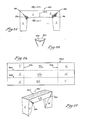
- Figures 30 and 31 are other additional, differently shaped polygonal sheets shown'with the required fold lines upon them, that when folded and pinched as previously described would yield other additional modules according to the appended claims.
Landscapes
- Engineering & Computer Science (AREA)
- Architecture (AREA)
- Civil Engineering (AREA)
- Structural Engineering (AREA)
- Physics & Mathematics (AREA)
- Electromagnetism (AREA)
- Tents Or Canopies (AREA)
- Rod-Shaped Construction Members (AREA)
Claims (17)
Priority Applications (4)
| Application Number | Priority Date | Filing Date | Title |
|---|---|---|---|
| US06/230,899 US4502257A (en) | 1981-02-02 | 1981-02-02 | Structural modules |
| EP85301465A EP0193662B1 (de) | 1981-02-02 | 1985-03-04 | Bauelemente |
| DE8585301465T DE3565871D1 (de) | 1985-03-04 | 1985-03-04 | Stuctural modules |
| AT85301465T ATE38260T1 (de) | 1985-03-04 | 1985-03-04 | Bauelemente. |
Applications Claiming Priority (2)
| Application Number | Priority Date | Filing Date | Title |
|---|---|---|---|
| US06/230,899 US4502257A (en) | 1981-02-02 | 1981-02-02 | Structural modules |
| EP85301465A EP0193662B1 (de) | 1981-02-02 | 1985-03-04 | Bauelemente |
Publications (2)
| Publication Number | Publication Date |
|---|---|
| EP0193662A1 EP0193662A1 (de) | 1986-09-10 |
| EP0193662B1 true EP0193662B1 (de) | 1988-10-26 |
Family
ID=26098295
Family Applications (1)
| Application Number | Title | Priority Date | Filing Date |
|---|---|---|---|
| EP85301465A Expired EP0193662B1 (de) | 1981-02-02 | 1985-03-04 | Bauelemente |
Country Status (2)
| Country | Link |
|---|---|
| US (1) | US4502257A (de) |
| EP (1) | EP0193662B1 (de) |
Families Citing this family (7)
| Publication number | Priority date | Publication date | Assignee | Title |
|---|---|---|---|---|
| US4502257A (en) * | 1981-02-02 | 1985-03-05 | Gary Diamond | Structural modules |
| US5553206A (en) * | 1993-02-12 | 1996-09-03 | International Business Machines Corporation | Method and system for producing mesh representations of objects |
| US5540013A (en) * | 1993-09-13 | 1996-07-30 | Diamond; Gary C. | Stellate hinged polygons forming a family of complex polyhedrons having discrete interiors and exteriors |
| US7814723B2 (en) * | 2006-09-25 | 2010-10-19 | Vanelverdinghe Jeffry L | Beam and truss structure for a canopy |
| US8959845B2 (en) * | 2009-12-23 | 2015-02-24 | Liberty Diversified International, Inc. | System and method for structure design |
| US11638884B1 (en) * | 2021-10-28 | 2023-05-02 | Zhejiang Benlai Household Technology Co., Ltd. | Basic connecting block and connecting block group |
| US20240149184A1 (en) * | 2022-05-19 | 2024-05-09 | Full Sun LLC | Toy construction kits and related methods |
Family Cites Families (13)
| Publication number | Priority date | Publication date | Assignee | Title |
|---|---|---|---|---|
| AT224317B (de) * | 1961-07-15 | 1962-11-12 | Voest Ag | Hallenkonstruktion und Verfahren zur Errichtung derselben |
| US3394506A (en) * | 1963-02-07 | 1968-07-30 | Beta Aluminium Products Ltd | Roofing medium |
| US3299585A (en) * | 1963-05-14 | 1967-01-24 | Arnold H Wilkins | Building construction |
| DE1450432B2 (de) * | 1963-06-27 | 1976-01-08 | Technigaz S.A., Paris | Abwickelbare Dehnungswand tür einen Behälter |
| US3354591A (en) * | 1964-12-07 | 1967-11-28 | Fuller Richard Buckminster | Octahedral building truss |
| US3557501A (en) * | 1966-03-28 | 1971-01-26 | Arpad Kolozsvary | Folded plate structures and components therefor |
| FR1483917A (fr) * | 1966-04-26 | 1967-06-09 | élément de construction préfabriquée | |
| US3600825A (en) * | 1968-08-19 | 1971-08-24 | Peter J Pearce | Synthesized natural geometric structures |
| US3568381A (en) * | 1968-11-27 | 1971-03-09 | Jesse R Hale | Structural system utilizing membrane structural panels having double ruled quadric surfaces |
| US3921349A (en) * | 1969-01-08 | 1975-11-25 | Arpad Kolozsvary | Structural component and structures comprising the same |
| US3931697A (en) * | 1972-01-10 | 1976-01-13 | Synestructics, Inc. | Modular curved surface space structures |
| US3774358A (en) * | 1972-09-18 | 1973-11-27 | J Hale | Structural membrane panel formed from saddle shaped surface |
| US4502257A (en) * | 1981-02-02 | 1985-03-05 | Gary Diamond | Structural modules |
-
1981
- 1981-02-02 US US06/230,899 patent/US4502257A/en not_active Expired - Fee Related
-
1985
- 1985-03-04 EP EP85301465A patent/EP0193662B1/de not_active Expired
Also Published As
| Publication number | Publication date |
|---|---|
| EP0193662A1 (de) | 1986-09-10 |
| US4502257A (en) | 1985-03-05 |
Similar Documents
| Publication | Publication Date | Title |
|---|---|---|
| US3354591A (en) | Octahedral building truss | |
| US3974600A (en) | Minimum inventory maximum diversity building system | |
| US5235791A (en) | Deck plate | |
| US3237362A (en) | Structural unit for supporting loads and resisting stresses | |
| US3346998A (en) | Structures formed exclusively of flat panelled right triangular building components | |
| US3925941A (en) | Modular curved surface space structures | |
| US3931697A (en) | Modular curved surface space structures | |
| US4012872A (en) | Geodesic dome-like panels | |
| JP2000517015A (ja) | 二重網状組織ドーム構造 | |
| US3953948A (en) | Homohedral construction employing icosahedron | |
| US4502257A (en) | Structural modules | |
| US4068422A (en) | Roofing for domical shell structure | |
| US5904006A (en) | Construction module, panel and system | |
| JPS61501158A (ja) | ド−ム建物構造体 | |
| US4555878A (en) | Structural element for constructions | |
| US3893277A (en) | Building panels | |
| US4182086A (en) | Building construction of A-shaped elements | |
| US4794742A (en) | Multi-conic shell and method of forming same | |
| US3204372A (en) | Building panel and method of making same | |
| US3280518A (en) | Hyperbolic paraboloid roof structure and method of constructing the frame thereof | |
| NZ211290A (en) | Fold sheet forms structure with curved surfaces | |
| US4685257A (en) | Shelter roof structure | |
| JPS61207743A (ja) | 複合的な多辺立体モジユ−ル | |
| KR900002277B1 (ko) | 모듀울 | |
| JP2023126073A (ja) | 盤状立体トラス構造 |
Legal Events
| Date | Code | Title | Description |
|---|---|---|---|
| PUAI | Public reference made under article 153(3) epc to a published international application that has entered the european phase |
Free format text: ORIGINAL CODE: 0009012 |
|
| AK | Designated contracting states |
Kind code of ref document: A1 Designated state(s): AT BE CH DE FR GB IT LI LU NL SE |
|
| 17P | Request for examination filed |
Effective date: 19861110 |
|
| 17Q | First examination report despatched |
Effective date: 19870928 |
|
| GRAA | (expected) grant |
Free format text: ORIGINAL CODE: 0009210 |
|
| AK | Designated contracting states |
Kind code of ref document: B1 Designated state(s): AT BE CH DE FR GB IT LI LU NL SE |
|
| PG25 | Lapsed in a contracting state [announced via postgrant information from national office to epo] |
Ref country code: IT Free format text: LAPSE BECAUSE OF FAILURE TO SUBMIT A TRANSLATION OF THE DESCRIPTION OR TO PAY THE FEE WITHIN THE PRESCRIBED TIME-LIMIT;WARNING: LAPSES OF ITALIAN PATENTS WITH EFFECTIVE DATE BEFORE 2007 MAY HAVE OCCURRED AT ANY TIME BEFORE 2007. THE CORRECT EFFECTIVE DATE MAY BE DIFFERENT FROM THE ONE RECORDED. Effective date: 19881026 Ref country code: BE Effective date: 19881026 Ref country code: CH Effective date: 19881026 Ref country code: AT Effective date: 19881026 Ref country code: LI Effective date: 19881026 Ref country code: SE Effective date: 19881026 Ref country code: NL Effective date: 19881026 |
|
| REF | Corresponds to: |
Ref document number: 38260 Country of ref document: AT Date of ref document: 19881115 Kind code of ref document: T |
|
| REF | Corresponds to: |
Ref document number: 3565871 Country of ref document: DE Date of ref document: 19881201 |
|
| ET | Fr: translation filed | ||
| REG | Reference to a national code |
Ref country code: CH Ref legal event code: PL |
|
| NLV1 | Nl: lapsed or annulled due to failure to fulfill the requirements of art. 29p and 29m of the patents act | ||
| PG25 | Lapsed in a contracting state [announced via postgrant information from national office to epo] |
Ref country code: LU Free format text: LAPSE BECAUSE OF NON-PAYMENT OF DUE FEES Effective date: 19890331 |
|
| PLBE | No opposition filed within time limit |
Free format text: ORIGINAL CODE: 0009261 |
|
| STAA | Information on the status of an ep patent application or granted ep patent |
Free format text: STATUS: NO OPPOSITION FILED WITHIN TIME LIMIT |
|
| 26N | No opposition filed | ||
| PGFP | Annual fee paid to national office [announced via postgrant information from national office to epo] |
Ref country code: FR Payment date: 19900323 Year of fee payment: 6 |
|
| PGFP | Annual fee paid to national office [announced via postgrant information from national office to epo] |
Ref country code: GB Payment date: 19900331 Year of fee payment: 6 |
|
| PGFP | Annual fee paid to national office [announced via postgrant information from national office to epo] |
Ref country code: DE Payment date: 19900405 Year of fee payment: 6 |
|
| PG25 | Lapsed in a contracting state [announced via postgrant information from national office to epo] |
Ref country code: GB Effective date: 19910304 |
|
| GBPC | Gb: european patent ceased through non-payment of renewal fee | ||
| PG25 | Lapsed in a contracting state [announced via postgrant information from national office to epo] |
Ref country code: DE Effective date: 19920101 |
|
| PG25 | Lapsed in a contracting state [announced via postgrant information from national office to epo] |
Ref country code: FR Effective date: 19950731 |
|
| REG | Reference to a national code |
Ref country code: FR Ref legal event code: ST |
|
| PG25 | Lapsed in a contracting state [announced via postgrant information from national office to epo] |
Ref country code: FR Effective date: 19910331 |