EP0193526B1 - Method and apparatus for treating hay - Google Patents
Method and apparatus for treating hay Download PDFInfo
- Publication number
- EP0193526B1 EP0193526B1 EP19840903157 EP84903157A EP0193526B1 EP 0193526 B1 EP0193526 B1 EP 0193526B1 EP 19840903157 EP19840903157 EP 19840903157 EP 84903157 A EP84903157 A EP 84903157A EP 0193526 B1 EP0193526 B1 EP 0193526B1
- Authority
- EP
- European Patent Office
- Prior art keywords
- hay
- steam
- conditioner
- cover
- windrow
- Prior art date
- Legal status (The legal status is an assumption and is not a legal conclusion. Google has not performed a legal analysis and makes no representation as to the accuracy of the status listed.)
- Expired
Links
- 238000000034 method Methods 0.000 title claims description 7
- 239000000463 material Substances 0.000 claims abstract description 15
- 230000000717 retained effect Effects 0.000 claims description 2
- 240000004658 Medicago sativa Species 0.000 description 9
- 235000010624 Medicago sativa Nutrition 0.000 description 9
- 241000196324 Embryophyta Species 0.000 description 4
- 238000001035 drying Methods 0.000 description 4
- 238000003306 harvesting Methods 0.000 description 3
- 230000014759 maintenance of location Effects 0.000 description 3
- 230000035515 penetration Effects 0.000 description 3
- 238000003860 storage Methods 0.000 description 3
- 230000002411 adverse Effects 0.000 description 2
- 230000003750 conditioning effect Effects 0.000 description 2
- 230000000694 effects Effects 0.000 description 2
- 238000004519 manufacturing process Methods 0.000 description 2
- 230000007246 mechanism Effects 0.000 description 2
- 235000016709 nutrition Nutrition 0.000 description 2
- 230000008569 process Effects 0.000 description 2
- 239000000047 product Substances 0.000 description 2
- 238000010025 steaming Methods 0.000 description 2
- 241001049809 Gonocalyx Species 0.000 description 1
- 241000219823 Medicago Species 0.000 description 1
- 235000017587 Medicago sativa ssp. sativa Nutrition 0.000 description 1
- 240000000528 Ricinus communis Species 0.000 description 1
- 235000004443 Ricinus communis Nutrition 0.000 description 1
- 230000009471 action Effects 0.000 description 1
- 230000015572 biosynthetic process Effects 0.000 description 1
- 238000004061 bleaching Methods 0.000 description 1
- 238000002485 combustion reaction Methods 0.000 description 1
- 230000006835 compression Effects 0.000 description 1
- 238000007906 compression Methods 0.000 description 1
- 230000001143 conditioned effect Effects 0.000 description 1
- 230000000593 degrading effect Effects 0.000 description 1
- 230000001419 dependent effect Effects 0.000 description 1
- 238000013461 design Methods 0.000 description 1
- 230000006866 deterioration Effects 0.000 description 1
- 230000003090 exacerbative effect Effects 0.000 description 1
- 238000002386 leaching Methods 0.000 description 1
- 235000012054 meals Nutrition 0.000 description 1
- 230000004048 modification Effects 0.000 description 1
- 238000012986 modification Methods 0.000 description 1
- 235000021049 nutrient content Nutrition 0.000 description 1
- 239000012466 permeate Substances 0.000 description 1
- 238000012545 processing Methods 0.000 description 1
- 230000002269 spontaneous effect Effects 0.000 description 1
- 238000012360 testing method Methods 0.000 description 1
- XLYOFNOQVPJJNP-UHFFFAOYSA-N water Substances O XLYOFNOQVPJJNP-UHFFFAOYSA-N 0.000 description 1
Images


Classifications
-
- A—HUMAN NECESSITIES
- A01—AGRICULTURE; FORESTRY; ANIMAL HUSBANDRY; HUNTING; TRAPPING; FISHING
- A01D—HARVESTING; MOWING
- A01D82/00—Crop conditioners, i.e. machines for crushing or bruising stalks
-
- A—HUMAN NECESSITIES
- A01—AGRICULTURE; FORESTRY; ANIMAL HUSBANDRY; HUNTING; TRAPPING; FISHING
- A01D—HARVESTING; MOWING
- A01D84/00—Haymakers not provided for in a single one of groups A01D76/00 - A01D82/00
Definitions
- This invention relates to the treating of hay prior to baling.
- the lucerne When the lucerne is ready to harvest it is cut leaving a stubble of approximately 5 cm. The cut lucerne is raked mechanically into parallel rows called windrows and left to dry for 3 to 4 days. The drying time is dependent upon climatic conditions and allows the optimum baling moisture content to be attained, at approximately 17% to 20%. Baling is carried out mechanically by a machine with a forwardly-mounted pick up reel.
- the pick up reel feeds the cured windrow material into the compressing chamber of the hay-baler where it is compressed into masses of appropriate size and weight and then tied with wire or twine to form bales.
- the bales are allowed to fall onto the ground at regular intervals and are then picked up and taken to a suitable storage site for subsequent disposal either directly as stock feed or for the production of chaff or meal at some later date.
- Baling with excessively moist hay leads to mould growth, deterioration during storage and an attendant risk of spontaneous combustion. Conversely, baling under too dry conditions results in leaf fracture and subsequent loss of nutrient content and a reduced market price.
- Exacerbating the problem of optimising moisture content is the characteristic differential drying rate between leaf and stem. The leaf dries faster than the stem so that when the stem reaches optimal baling moisture content, the leaf is overdry, brittle and easily fractured when handled.
- baling is conducted whenever the dew forms, usually over a three or four hour period say between 3 am and 9 am.
- Dew does not form regularly or predictably and during the summer harvest time, long periods without dew may occur-up to 10 days or more.
- the dew may be too heavy and an additional time is required for the hay to dry.
- a market survey has shown that such unfavourable conditions typically affect two to three cuts out of the usual six in the growing season. That is, one-third of the lucerne grower's income can be adversely affected apart from losses due to storm damage. After excessive drying, baled hay can only command a low market price. Under extreme conditions, the windrowed hay may be raked aside and abandoned.
- a suitable hay conditioner is disclosed in AU-B-38685n8 which describes a hay conditioner having an elongated treatment chamber with opposed side walls and a top wall by which a longitudinal portion of a windrow is enclosed, a plurality of steam outlet nozzles within the treatment chamber and means for supplying steam to the nozzles whereby the windrowed material is treated with steam emerging from the outlet nozzles as the hay conditioner is caused to travel along the row.
- This known hay conditioner further comprises a conveyor forming the bottom of the treatment chamber.
- a hay conditioner which comprises an elongated treatment cover having opposed side walls and a top wall adapted to be positioned so as to enclose substantially a longitudinal portion of a windrow lying on the ground, over which the hay conditioner is caused to travel, a plurality of steam outlet nozzles associated with the treatment cover and means for supplying steam to the nozzles whereby the windrowed material is treated with steam emerging from said steam outlet nozzles as the hay conditioner is caused to progress along the windrow.
- the invention also provides a method of treating hay using a hay conditioner as set out in the last preceding paragraph prior to baling wherein the hay is subjected to steam treatment within a cover positioned to enclose a longitudinal portion of a windrow lying on the ground, wherein the moisture content of the steam is less than 1.5%, for sufficient time to allow some of the steam to penetrate the cell structure of the hay.
- the hay conditioner shown in Figs. 1 to 3 is mounted on a conventional tractor-towed hay- baler having a pick-up reel 1 that includes spring biased rake tines rotating within a slotted guard arrangement.
- the pick-up reel 1 feeds the windrowed material into a feed opening 2 where a feeder bar moves the material into the baling chamber 4 for compression into bales.
- a hay-baler is supported by wheels 3 and is coupled to the take off point of a tractor.
- the baler includes either a twine-knotting or a wire-twisting mechanism by means of which the compressed bales are completed before they are allowed to fall onto the ground.
- the hay conditioner includes a treatment cover which in this instance consists of an elongated, tunnel-like structure having opposed side walls 5 and 6 joined by a top wall or hood 7 of part circular cross section.
- the treatment cover is so dimensioned that it will be able to span the width of a windrow.
- Hay pick-up means may be provided at the forward end of the treatment cover if desired.
- the hay pick up means includes a number of V-shaped elements 8a to 8g which are equally spaced across the forward end of the treatment cover with their apices pointing forwardly and downwardly so that they terminate fractionally above ground level.
- the weight of the forward end of the treatment cover is sufficient to ensure that the hay conditioner skids along the ground on skid means 13 and 14.
- Steam manifolds 9 and 10 extend between the skid means 13 and 14 and provide a convenient support base for the V-shaped elements. In this instance, two steam manifolds 9 and 10 are shown, but it will be realised that more or fewer may be used.
- Each of the steam manifolds is provided with a plurality of steam outlet nozzles and it will be noted that manifold 9 has its nozzles equally spaced over its whole length but that manifold 10 has its nozzles closer together and only in the middle section of the manifold. Such an arrangement ensures that windrows of different widths may be efficiently steam treated without wastage of steam.
- Flow of steam to the manifolds is controlled by a cock 11 whereby the steam conduit 12 may be selectively connected to manifold 9 or manifold 10.
- the steam conduit 12 is connected to the steam generator 16 (of conventional kind) which is mounted on the two wheeled trailer 17 detachably connected to the rear end of the hay baler.
- the trailing position of the trailer 17 is immaterial, but should be such that it does not interfere with the discharge of bales from the baling chamber 4.
- Steam generator 16 may be adapted for operation from the tractor cab.
- the forward end of the treatment cover may be modified as desired.
- the V-shaped elements may be omitted leaving the steam manifolds to act as a hay pick-up means, sliding beneath the windrowed material as the conditioner is moved along the windrow.
- the V-shaped elements may be arranged so as to be readily detachable from the manifolds or, alternatively, the manifolds and integral V-shaped elements may be detached from the skids 13 and 14 and replaced by a steam manifold not having the V-shaped elements.
- the steam could be introduced through the top or sides of the cover.
- the hay conditioner is connected to the hay baler by means of the cantilever arms 15.
- the arms 15 are raised and lowered by a hydraulic arrangement (not shown) under the control of the operator of the hay-baler.
- the conditioner should be mounted on the hay-baler so that the longitudinal axis of the treatment cover is in register with the centre line of the feed opening of the hay-baler.
- the treatment cover is of sufficient length to maintain the steam environment around the windrow for approximately 5 seconds which is the time necessary for optimum penetration of steam into the cell structure of the leaf of the dried lucerne.
- the minimum 5 second retention time necessitates that the hay conditioner travels at approximately 3 km/hr when treating very dry lucerne. This compares with a normal speed during baling of approximately 6 km/hr or top speed with fairly light windrows of approximately 10 km/hr. This slow baling speed may be overcome by pre-raking light windrows into heavier windrows. This may be achieved using existing hay rakes.
- Figure 4 shows a second embodiment of the present invention which has particular application in windy or blustery conditions. Under such conditions, windrow material tends to become 'teased' or 'fluffed out' to such an extent that the tunnel-like structure 5, 6 and 7 shown in Figs. 1 to 3 is too close to the ground to clear the windrow.
- FIG. 4 depicts an elongated tunnel-like structure having opposed sidewalls 25 and 26 joined by a top wall or hood 27 of varying part- circular cross section.
- Hood 27 is configured so as to be perhaps 40 to 50 cms above the ground at the leading end reducing to, say, 28 cms at a point 130 cms back drom the leading end. From this point to the trailing end of the structure, the top of hood 27 is parallel to sidewalls 25 and 26.
- the forward end of the cover may be furnished with V-shaped elements 28a to 28g and one or more steam manifold 29. Skids 30 and 31, or castors or the like, are provided as before.
- a feed conveyor 32 may be positioned at the top of the cover to provide a driving run from the open end of the cover into the cover proper. This may take the form of an endless belt 33, having transverse battens 34, travelling about rollers or pulleys 35 and 36 journalled in the top of the hood, the width of the belt being perhaps in the order of 10 cms.
- the function of this feed conveyor is to prevent windrow material from being 'bulldozed' by the cover. After steaming, the new limper hay is deposited back onto the ground and formed into a windrow more compact than it was before being conditioned.
- the preferred mode of operation of the hay conditioner according to the embodiments of the present invention shown in the drawings is as follows: as the hay-baler is towed along so as to traverse a windrow, the hay is lifted by the V-shaped elements of the pick up means and the windrowed material is then steamed by jets of steam from the manifold. In the modification of the invention without the pick-up means, the windrowed material is both lifted and steamed by the manifold. In either case, the steamed windrow material falls back onto the ground to reform the windrow. In the case of steam fed from the top or sides of the cover, the windrowed material will not be disturbed.
- the hay-baler Until the hay is picked up by the pick up reel of the haybaler, it is covered by the treatment cover of the hay conditioner.
- the mechanisms of the hay-baler are driven by shaft 18 which is universally coupled to the power take off shaft of the towing tractor.
- the treatment cover should be as short as possible to enhance manoeuvrability, it should nevertheless be long enough to condition hay properly in its passage thereover. In practice, a length of the order of 3 to 4 metres will be found to be suitable.
- a feed roller arrangement may well be incorporated in the elongated, box-like structure.
- the steam geneator 16 may be of any convenient kind. Empirical testing indicates that dry steam at 35-45 pounds/square inch pressure is optimal for the conditioning of lucerne leaf.
- dry steam embraces steam having less than 1.5% moisture content.
- the hay treatment process of the invention uses "dry" steam as a dew substitute to permeate the cell structure of the leaf of the lucern or other hay crop with sufficient moisture (almost instantaneously) to restore its malleable/supple properties so that it is able to undergo mechanical handling without degrading the overall plant structure. Retention of the leaf in the cover for a predetermined time is essential to obtain the required moisture content within the leaf so that the nutritional value of the crop will be retained when it is baled.
Landscapes
- Life Sciences & Earth Sciences (AREA)
- Environmental Sciences (AREA)
- Processing Of Solid Wastes (AREA)
- Apparatuses For Bulk Treatment Of Fruits And Vegetables And Apparatuses For Preparing Feeds (AREA)
Abstract
Description
- This invention relates to the treating of hay prior to baling.
- For the sake of brevity, the invention will be described in relation to lucerne (alfalfa), however, it is to be understood that the invention is not limited thereto as it may be applied to other crops that are used to produce hay.
- When the lucerne is ready to harvest it is cut leaving a stubble of approximately 5 cm. The cut lucerne is raked mechanically into parallel rows called windrows and left to dry for 3 to 4 days. The drying time is dependent upon climatic conditions and allows the optimum baling moisture content to be attained, at approximately 17% to 20%. Baling is carried out mechanically by a machine with a forwardly-mounted pick up reel.
- When baling commences, the pick up reel feeds the cured windrow material into the compressing chamber of the hay-baler where it is compressed into masses of appropriate size and weight and then tied with wire or twine to form bales. The bales are allowed to fall onto the ground at regular intervals and are then picked up and taken to a suitable storage site for subsequent disposal either directly as stock feed or for the production of chaff or meal at some later date.
- One problem associated with the formation of hay from lucerne is that the leaf of the lucerne becomes brittle when dried. If handled in this condition, the leaf will break away from the stem of the plant thereby reducing the crop's nutritional content as well as the market value of the crop.
- The production of a premium product (which will command a premium price) depends on baling at the optimum moisture content which can be difficult to achieve as weather conditions are unpredictable.
- Baling with excessively moist hay (i.e.: over 20% moisture content) leads to mould growth, deterioration during storage and an attendant risk of spontaneous combustion. Conversely, baling under too dry conditions results in leaf fracture and subsequent loss of nutrient content and a reduced market price. Exacerbating the problem of optimising moisture content is the characteristic differential drying rate between leaf and stem. The leaf dries faster than the stem so that when the stem reaches optimal baling moisture content, the leaf is overdry, brittle and easily fractured when handled.
- The farmer overcomes this brittle leaf problem by baling at night or early morning when moisture from prevailing dew conditions makes the leaf more supple. Ideally, baling is conducted whenever the dew forms, usually over a three or four hour period say between 3 am and 9 am. Dew does not form regularly or predictably and during the summer harvest time, long periods without dew may occur-up to 10 days or more. Conversely, the dew may be too heavy and an additional time is required for the hay to dry. In Australia, a market survey has shown that such unfavourable conditions typically affect two to three cuts out of the usual six in the growing season. That is, one-third of the lucerne grower's income can be adversely affected apart from losses due to storm damage. After excessive drying, baled hay can only command a low market price. Under extreme conditions, the windrowed hay may be raked aside and abandoned.
- Alternatively it has been proposed to treat the hay immediately prior to baling, using a suitable hay container, so that it is in a suitable condition for baling.
- One suitable hay conditioner is disclosed in AU-B-38685n8 which describes a hay conditioner having an elongated treatment chamber with opposed side walls and a top wall by which a longitudinal portion of a windrow is enclosed, a plurality of steam outlet nozzles within the treatment chamber and means for supplying steam to the nozzles whereby the windrowed material is treated with steam emerging from the outlet nozzles as the hay conditioner is caused to travel along the row. This known hay conditioner, however, further comprises a conveyor forming the bottom of the treatment chamber.
- It is an object of the present invention to provide a process of an apparatus for conditioning hay which simulates the action of dew to make the leaf supple immediately prior to baling.
- According to the invention, there is provided a hay conditioner which comprises an elongated treatment cover having opposed side walls and a top wall adapted to be positioned so as to enclose substantially a longitudinal portion of a windrow lying on the ground, over which the hay conditioner is caused to travel, a plurality of steam outlet nozzles associated with the treatment cover and means for supplying steam to the nozzles whereby the windrowed material is treated with steam emerging from said steam outlet nozzles as the hay conditioner is caused to progress along the windrow.
- The invention also provides a method of treating hay using a hay conditioner as set out in the last preceding paragraph prior to baling wherein the hay is subjected to steam treatment within a cover positioned to enclose a longitudinal portion of a windrow lying on the ground, wherein the moisture content of the steam is less than 1.5%, for sufficient time to allow some of the steam to penetrate the cell structure of the hay.
- In order that the invention may be more readily understood and put into practical effect, reference will now be made to the accompanying drawings in which:
- Fig. 1 is a schematic side elevational view of a hay conditioner according to one embodiment of the invention,
- Fig. 2 is a top plan view of the hay conditioner shown in Fig. 1,
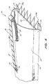
- Fig. 3 is a partial perspective view, on an enlarged scale, showing the leading end of the hay conditioner, and,
- Fig. 4 is a partial perspective view of a second embodiment of the invention.
- The hay conditioner shown in Figs. 1 to 3 is mounted on a conventional tractor-towed hay- baler having a pick-up reel 1 that includes spring biased rake tines rotating within a slotted guard arrangement. The pick-up reel 1 feeds the windrowed material into a
feed opening 2 where a feeder bar moves the material into thebaling chamber 4 for compression into bales. Such a hay-baler is supported bywheels 3 and is coupled to the take off point of a tractor. The baler includes either a twine-knotting or a wire-twisting mechanism by means of which the compressed bales are completed before they are allowed to fall onto the ground. - The hay conditioner includes a treatment cover which in this instance consists of an elongated, tunnel-like structure having
opposed side walls 5 and 6 joined by a top wall orhood 7 of part circular cross section. The treatment cover is so dimensioned that it will be able to span the width of a windrow. - Hay pick-up means may be provided at the forward end of the treatment cover if desired. In this instance, the hay pick up means includes a number of V-
shaped elements 8a to 8g which are equally spaced across the forward end of the treatment cover with their apices pointing forwardly and downwardly so that they terminate fractionally above ground level. The weight of the forward end of the treatment cover is sufficient to ensure that the hay conditioner skids along the ground on skid means 13 and 14. -
Steam manifolds 9 and 10 extend between theskid means steam manifolds 9 and 10 are shown, but it will be realised that more or fewer may be used. - Each of the steam manifolds is provided with a plurality of steam outlet nozzles and it will be noted that manifold 9 has its nozzles equally spaced over its whole length but that
manifold 10 has its nozzles closer together and only in the middle section of the manifold. Such an arrangement ensures that windrows of different widths may be efficiently steam treated without wastage of steam. Flow of steam to the manifolds is controlled by acock 11 whereby thesteam conduit 12 may be selectively connected to manifold 9 ormanifold 10. - The
steam conduit 12 is connected to the steam generator 16 (of conventional kind) which is mounted on the twowheeled trailer 17 detachably connected to the rear end of the hay baler. The trailing position of thetrailer 17 is immaterial, but should be such that it does not interfere with the discharge of bales from thebaling chamber 4.Steam generator 16 may be adapted for operation from the tractor cab. - The forward end of the treatment cover may be modified as desired. For example, the V-shaped elements may be omitted leaving the steam manifolds to act as a hay pick-up means, sliding beneath the windrowed material as the conditioner is moved along the windrow. Thus, the V-shaped elements may be arranged so as to be readily detachable from the manifolds or, alternatively, the manifolds and integral V-shaped elements may be detached from the
skids - In this instance, the hay conditioner is connected to the hay baler by means of the
cantilever arms 15. Thearms 15 are raised and lowered by a hydraulic arrangement (not shown) under the control of the operator of the hay-baler. It will be appreciated that the conditioner should be mounted on the hay-baler so that the longitudinal axis of the treatment cover is in register with the centre line of the feed opening of the hay-baler. - The treatment cover is of sufficient length to maintain the steam environment around the windrow for approximately 5 seconds which is the time necessary for optimum penetration of steam into the cell structure of the leaf of the dried lucerne. The minimum 5 second retention time necessitates that the hay conditioner travels at approximately 3 km/hr when treating very dry lucerne. This compares with a normal speed during baling of approximately 6 km/hr or top speed with fairly light windrows of approximately 10 km/hr. This slow baling speed may be overcome by pre-raking light windrows into heavier windrows. This may be achieved using existing hay rakes.
- Figure 4 shows a second embodiment of the present invention which has particular application in windy or blustery conditions. Under such conditions, windrow material tends to become 'teased' or 'fluffed out' to such an extent that the tunnel-
like structure - Thus, Fig. 4 depicts an elongated tunnel-like structure having opposed sidewalls 25 and 26 joined by a top wall or
hood 27 of varying part- circular cross section.Hood 27 is configured so as to be perhaps 40 to 50 cms above the ground at the leading end reducing to, say, 28 cms at a point 130 cms back drom the leading end. From this point to the trailing end of the structure, the top ofhood 27 is parallel to sidewalls 25 and 26. - As in the previously described embodiment, the forward end of the cover may be furnished with V-shaped elements 28a to 28g and one or
more steam manifold 29.Skids - A
feed conveyor 32 may be positioned at the top of the cover to provide a driving run from the open end of the cover into the cover proper. This may take the form of anendless belt 33, havingtransverse battens 34, travelling about rollers or pulleys 35 and 36 journalled in the top of the hood, the width of the belt being perhaps in the order of 10 cms. The function of this feed conveyor is to prevent windrow material from being 'bulldozed' by the cover. After steaming, the new limper hay is deposited back onto the ground and formed into a windrow more compact than it was before being conditioned. - The preferred mode of operation of the hay conditioner according to the embodiments of the present invention shown in the drawings is as follows: as the hay-baler is towed along so as to traverse a windrow, the hay is lifted by the V-shaped elements of the pick up means and the windrowed material is then steamed by jets of steam from the manifold. In the modification of the invention without the pick-up means, the windrowed material is both lifted and steamed by the manifold. In either case, the steamed windrow material falls back onto the ground to reform the windrow. In the case of steam fed from the top or sides of the cover, the windrowed material will not be disturbed. Until the hay is picked up by the pick up reel of the haybaler, it is covered by the treatment cover of the hay conditioner. The mechanisms of the hay-baler are driven by
shaft 18 which is universally coupled to the power take off shaft of the towing tractor. - While the treatment cover should be as short as possible to enhance manoeuvrability, it should nevertheless be long enough to condition hay properly in its passage thereover. In practice, a length of the order of 3 to 4 metres will be found to be suitable. To aid the travel of the windrow material through the treatment cover, a feed roller arrangement may well be incorporated in the elongated, box-like structure.
- The
steam geneator 16 may be of any convenient kind. Empirical testing indicates that dry steam at 35-45 pounds/square inch pressure is optimal for the conditioning of lucerne leaf. The term "dry" steam embraces steam having less than 1.5% moisture content. - The hay treatment process of the invention uses "dry" steam as a dew substitute to permeate the cell structure of the leaf of the lucern or other hay crop with sufficient moisture (almost instantaneously) to restore its malleable/supple properties so that it is able to undergo mechanical handling without degrading the overall plant structure. Retention of the leaf in the cover for a predetermined time is essential to obtain the required moisture content within the leaf so that the nutritional value of the crop will be retained when it is baled.
- "Dry" steam is necessary to achieve rapid, effective and preferential permeation of the leaf (with respect to the plant stem) so as to be practical in a mobile situation.
- Small water droplets have been tried and found unsuccessful because the droplet size has been too large and surface tension effects have prevented rapid penetration of the leaf surface. Also, excess moisture (droplets) was left on the stem, raising the overall moisture content of the baled crop. With the dry steam, only the leaf is able to pick up significant moisture and the thick, waxy stem is unaffected; hence the overall moisture content of the baled crop is not adversely affected and remains optimum for storage (as is the case with natural dew).
- Hence, instigation of this new improved method for harvesting hay for baling at the optimum overall moisture content requires:
- 1. A source of dry steam (from a steam generator or boiler).
- 2. A successful combination of nozzle design/ size/geometry/number, steam flow rate, steam temperature and pressure so that the steam effectively penetrates the crop before too much is condensed.
- 3. A contained environment for efficient steam processing of the crop and to minimise moisture losses from the leaf before the crop enters the baling chamber of the baler.
- 4. An appropriate retention time of the crop in the steaming environment to allow effective spread of the steam to all the leaf surfaces and effective penetration of the steam from the leaf surface to the plant cells within the leaf. (This takes about 5 seconds with the present embodiment of the invention).
- Thus, the advantages of this new system are:
- (a) Optimum bale and leaf moisture content is achievable under a variety of weather conditions and time of day without reliance on dew.
- (b) The farmer has more control over baled hay product quality without reliance on weather.
- (c) The crop is baled faster-minimising leaching, bleaching, drying and storm losses and increasing annual yield (allowing faster regrowth of the next crop).
Claims (8)
Applications Claiming Priority (1)
| Application Number | Priority Date | Filing Date | Title |
|---|---|---|---|
| PCT/AU1984/000161 WO1986001372A1 (en) | 1984-08-27 | 1984-08-27 | Method and apparatus for treating hay |
Publications (3)
| Publication Number | Publication Date |
|---|---|
| EP0193526A1 EP0193526A1 (en) | 1986-09-10 |
| EP0193526A4 EP0193526A4 (en) | 1987-08-12 |
| EP0193526B1 true EP0193526B1 (en) | 1990-08-22 |
Family
ID=3761747
Family Applications (1)
| Application Number | Title | Priority Date | Filing Date |
|---|---|---|---|
| EP19840903157 Expired EP0193526B1 (en) | 1984-08-27 | 1984-08-27 | Method and apparatus for treating hay |
Country Status (3)
| Country | Link |
|---|---|
| EP (1) | EP0193526B1 (en) |
| DE (1) | DE3483046D1 (en) |
| WO (1) | WO1986001372A1 (en) |
Families Citing this family (2)
| Publication number | Priority date | Publication date | Assignee | Title |
|---|---|---|---|---|
| AU606317B2 (en) * | 1985-11-21 | 1991-02-07 | Riyate Pty Limited | treatment of crops |
| CN110101104A (en) * | 2019-06-05 | 2019-08-09 | 甘肃金科脉草业有限责任公司 | It is a kind of for improving the device of hay moisture content |
Family Cites Families (6)
| Publication number | Priority date | Publication date | Assignee | Title |
|---|---|---|---|---|
| US2909881A (en) * | 1956-07-17 | 1959-10-27 | Callahan Allie | Combination mower, drier and baler |
| US3585730A (en) * | 1969-01-17 | 1971-06-22 | George W Morse | Method and apparatus for the preservation of nutrients in forage |
| AU521457B2 (en) * | 1977-12-13 | 1982-04-01 | MAHER and' GROSVENOR FINLAY FRANCIS JACK | Hay conditioner |
| US4257215A (en) * | 1979-06-06 | 1981-03-24 | Jack Maher | Mobile chaff-cutter |
| AU6191580A (en) * | 1980-08-27 | 1982-03-04 | Maher, J. | Hay pre-conditioner |
| AU561014B2 (en) * | 1983-02-25 | 1987-04-30 | Riyate Pty Limited | Hay pre-conditioner |
-
1984
- 1984-08-27 WO PCT/AU1984/000161 patent/WO1986001372A1/en not_active Ceased
- 1984-08-27 EP EP19840903157 patent/EP0193526B1/en not_active Expired
- 1984-08-27 DE DE8484903157T patent/DE3483046D1/en not_active Expired - Fee Related
Also Published As
| Publication number | Publication date |
|---|---|
| EP0193526A1 (en) | 1986-09-10 |
| EP0193526A4 (en) | 1987-08-12 |
| DE3483046D1 (en) | 1990-09-27 |
| WO1986001372A1 (en) | 1986-03-13 |
Similar Documents
| Publication | Publication Date | Title |
|---|---|---|
| US4991342A (en) | Steam treatment of crops | |
| US5105563A (en) | Apparatus for harvesting and drying crops | |
| US5557859A (en) | Continuous process for harvesting, solar drying and accumulating hay or other crops | |
| US3834141A (en) | Pick-up baler, sprayer and compactor combination | |
| US5758479A (en) | Method and device for hay production | |
| US4662163A (en) | Mobile spray applicator and method of spraying forage | |
| Tullberg et al. | The effect of potassium carbonate solution on the drying of lucerne: 2. Field studies | |
| US6109008A (en) | Method and device for hay production | |
| Klinner et al. | The state of haymaking technology—a review | |
| US4873772A (en) | Steam treatment of crops | |
| WO1986001372A1 (en) | Method and apparatus for treating hay | |
| SU1516055A1 (en) | Method of harvesting cereal crops and grass for seeds | |
| US4254605A (en) | Hay conditioner | |
| AU606317B2 (en) | treatment of crops | |
| Dobie et al. | Ground level harvest of rice straw | |
| RU2195803C2 (en) | Method for separate flax harvesting (versions) | |
| RU2835354C1 (en) | Machine for harvesting industrial hemp and method for harvesting industrial hemp | |
| GB2354419A (en) | Method of and apparatus for crop production | |
| WO1991001080A2 (en) | Apparatus and method for harvesting crops | |
| Undersander | Harvesting impacts on forage quality | |
| CN115553133B (en) | Alfalfa stem bundling system and method | |
| US5678354A (en) | No-burn process for fostering growth of a mature perennial grass crop in a field | |
| CA2133544A1 (en) | Forage conditioning machine | |
| SU1753999A1 (en) | Method of harvesting silo crops | |
| RU2224411C2 (en) | Method for mowing of grass testicles |
Legal Events
| Date | Code | Title | Description |
|---|---|---|---|
| PUAI | Public reference made under article 153(3) epc to a published international application that has entered the european phase |
Free format text: ORIGINAL CODE: 0009012 |
|
| 17P | Request for examination filed |
Effective date: 19860512 |
|
| AK | Designated contracting states |
Kind code of ref document: A1 Designated state(s): DE FR GB |
|
| A4 | Supplementary search report drawn up and despatched |
Effective date: 19870812 |
|
| 17Q | First examination report despatched |
Effective date: 19880309 |
|
| GRAA | (expected) grant |
Free format text: ORIGINAL CODE: 0009210 |
|
| DIN1 | Information on inventor provided before grant (deleted) | ||
| RAP1 | Party data changed (applicant data changed or rights of an application transferred) |
Owner name: RIYATE PTY LIMITED |
|
| AK | Designated contracting states |
Kind code of ref document: B1 Designated state(s): DE FR GB |
|
| REF | Corresponds to: |
Ref document number: 3483046 Country of ref document: DE Date of ref document: 19900927 |
|
| ET | Fr: translation filed | ||
| PLBE | No opposition filed within time limit |
Free format text: ORIGINAL CODE: 0009261 |
|
| STAA | Information on the status of an ep patent application or granted ep patent |
Free format text: STATUS: NO OPPOSITION FILED WITHIN TIME LIMIT |
|
| 26N | No opposition filed | ||
| PGFP | Annual fee paid to national office [announced via postgrant information from national office to epo] |
Ref country code: DE Payment date: 20000918 Year of fee payment: 17 |
|
| REG | Reference to a national code |
Ref country code: GB Ref legal event code: IF02 |
|
| PG25 | Lapsed in a contracting state [announced via postgrant information from national office to epo] |
Ref country code: DE Free format text: LAPSE BECAUSE OF NON-PAYMENT OF DUE FEES Effective date: 20020501 |
|
| PGFP | Annual fee paid to national office [announced via postgrant information from national office to epo] |
Ref country code: FR Payment date: 20020830 Year of fee payment: 19 |
|
| PGFP | Annual fee paid to national office [announced via postgrant information from national office to epo] |
Ref country code: GB Payment date: 20020916 Year of fee payment: 19 |
|
| PG25 | Lapsed in a contracting state [announced via postgrant information from national office to epo] |
Ref country code: GB Free format text: LAPSE BECAUSE OF NON-PAYMENT OF DUE FEES Effective date: 20030827 |
|
| GBPC | Gb: european patent ceased through non-payment of renewal fee | ||
| PG25 | Lapsed in a contracting state [announced via postgrant information from national office to epo] |
Ref country code: FR Free format text: LAPSE BECAUSE OF NON-PAYMENT OF DUE FEES Effective date: 20040430 |
|
| REG | Reference to a national code |
Ref country code: FR Ref legal event code: ST |