EP0192593A1 - Procédé de fabrication d'un support intercalaire de membranes semi-perméables - Google Patents
Procédé de fabrication d'un support intercalaire de membranes semi-perméables Download PDFInfo
- Publication number
- EP0192593A1 EP0192593A1 EP86420049A EP86420049A EP0192593A1 EP 0192593 A1 EP0192593 A1 EP 0192593A1 EP 86420049 A EP86420049 A EP 86420049A EP 86420049 A EP86420049 A EP 86420049A EP 0192593 A1 EP0192593 A1 EP 0192593A1
- Authority
- EP
- European Patent Office
- Prior art keywords
- grid
- border
- support
- elastomer
- permeable
- Prior art date
- Legal status (The legal status is an assumption and is not a legal conclusion. Google has not performed a legal analysis and makes no representation as to the accuracy of the status listed.)
- Granted
Links
Images

Classifications
-
- B—PERFORMING OPERATIONS; TRANSPORTING
- B01—PHYSICAL OR CHEMICAL PROCESSES OR APPARATUS IN GENERAL
- B01D—SEPARATION
- B01D63/00—Apparatus in general for separation processes using semi-permeable membranes
- B01D63/08—Flat membrane modules
- B01D63/081—Manufacturing thereof
-
- B—PERFORMING OPERATIONS; TRANSPORTING
- B29—WORKING OF PLASTICS; WORKING OF SUBSTANCES IN A PLASTIC STATE IN GENERAL
- B29C—SHAPING OR JOINING OF PLASTICS; SHAPING OF MATERIAL IN A PLASTIC STATE, NOT OTHERWISE PROVIDED FOR; AFTER-TREATMENT OF THE SHAPED PRODUCTS, e.g. REPAIRING
- B29C31/00—Handling, e.g. feeding of the material to be shaped, storage of plastics material before moulding; Automation, i.e. automated handling lines in plastics processing plants, e.g. using manipulators or robots
- B29C31/04—Feeding of the material to be moulded, e.g. into a mould cavity
- B29C31/08—Feeding of the material to be moulded, e.g. into a mould cavity of preforms to be moulded, e.g. tablets, fibre reinforced preforms, extruded ribbons, tubes or profiles; Manipulating means specially adapted for feeding preforms, e.g. supports conveyors
-
- B—PERFORMING OPERATIONS; TRANSPORTING
- B29—WORKING OF PLASTICS; WORKING OF SUBSTANCES IN A PLASTIC STATE IN GENERAL
- B29C—SHAPING OR JOINING OF PLASTICS; SHAPING OF MATERIAL IN A PLASTIC STATE, NOT OTHERWISE PROVIDED FOR; AFTER-TREATMENT OF THE SHAPED PRODUCTS, e.g. REPAIRING
- B29C70/00—Shaping composites, i.e. plastics material comprising reinforcements, fillers or preformed parts, e.g. inserts
- B29C70/68—Shaping composites, i.e. plastics material comprising reinforcements, fillers or preformed parts, e.g. inserts by incorporating or moulding on preformed parts, e.g. inserts or layers, e.g. foam blocks
- B29C70/74—Moulding material on a relatively small portion of the preformed part, e.g. outsert moulding
- B29C70/76—Moulding on edges or extremities of the preformed part
- B29C70/763—Moulding on edges or extremities of the preformed part the edges being disposed in a substantial flat plane
-
- B—PERFORMING OPERATIONS; TRANSPORTING
- B29—WORKING OF PLASTICS; WORKING OF SUBSTANCES IN A PLASTIC STATE IN GENERAL
- B29C—SHAPING OR JOINING OF PLASTICS; SHAPING OF MATERIAL IN A PLASTIC STATE, NOT OTHERWISE PROVIDED FOR; AFTER-TREATMENT OF THE SHAPED PRODUCTS, e.g. REPAIRING
- B29C70/00—Shaping composites, i.e. plastics material comprising reinforcements, fillers or preformed parts, e.g. inserts
- B29C70/68—Shaping composites, i.e. plastics material comprising reinforcements, fillers or preformed parts, e.g. inserts by incorporating or moulding on preformed parts, e.g. inserts or layers, e.g. foam blocks
- B29C70/82—Forcing wires, nets or the like partially or completely into the surface of an article, e.g. by cutting and pressing
-
- B—PERFORMING OPERATIONS; TRANSPORTING
- B29—WORKING OF PLASTICS; WORKING OF SUBSTANCES IN A PLASTIC STATE IN GENERAL
- B29L—INDEXING SCHEME ASSOCIATED WITH SUBCLASS B29C, RELATING TO PARTICULAR ARTICLES
- B29L2031/00—Other particular articles
- B29L2031/14—Filters
-
- B—PERFORMING OPERATIONS; TRANSPORTING
- B29—WORKING OF PLASTICS; WORKING OF SUBSTANCES IN A PLASTIC STATE IN GENERAL
- B29L—INDEXING SCHEME ASSOCIATED WITH SUBCLASS B29C, RELATING TO PARTICULAR ARTICLES
- B29L2031/00—Other particular articles
- B29L2031/755—Membranes, diaphragms
-
- Y—GENERAL TAGGING OF NEW TECHNOLOGICAL DEVELOPMENTS; GENERAL TAGGING OF CROSS-SECTIONAL TECHNOLOGIES SPANNING OVER SEVERAL SECTIONS OF THE IPC; TECHNICAL SUBJECTS COVERED BY FORMER USPC CROSS-REFERENCE ART COLLECTIONS [XRACs] AND DIGESTS
- Y10—TECHNICAL SUBJECTS COVERED BY FORMER USPC
- Y10T—TECHNICAL SUBJECTS COVERED BY FORMER US CLASSIFICATION
- Y10T156/00—Adhesive bonding and miscellaneous chemical manufacture
- Y10T156/10—Methods of surface bonding and/or assembly therefor
- Y10T156/1052—Methods of surface bonding and/or assembly therefor with cutting, punching, tearing or severing
- Y10T156/1062—Prior to assembly
-
- Y—GENERAL TAGGING OF NEW TECHNOLOGICAL DEVELOPMENTS; GENERAL TAGGING OF CROSS-SECTIONAL TECHNOLOGIES SPANNING OVER SEVERAL SECTIONS OF THE IPC; TECHNICAL SUBJECTS COVERED BY FORMER USPC CROSS-REFERENCE ART COLLECTIONS [XRACs] AND DIGESTS
- Y10—TECHNICAL SUBJECTS COVERED BY FORMER USPC
- Y10T—TECHNICAL SUBJECTS COVERED BY FORMER US CLASSIFICATION
- Y10T156/00—Adhesive bonding and miscellaneous chemical manufacture
- Y10T156/10—Methods of surface bonding and/or assembly therefor
- Y10T156/1089—Methods of surface bonding and/or assembly therefor of discrete laminae to single face of additional lamina
- Y10T156/109—Embedding of laminae within face of additional laminae
-
- Y—GENERAL TAGGING OF NEW TECHNOLOGICAL DEVELOPMENTS; GENERAL TAGGING OF CROSS-SECTIONAL TECHNOLOGIES SPANNING OVER SEVERAL SECTIONS OF THE IPC; TECHNICAL SUBJECTS COVERED BY FORMER USPC CROSS-REFERENCE ART COLLECTIONS [XRACs] AND DIGESTS
- Y10—TECHNICAL SUBJECTS COVERED BY FORMER USPC
- Y10T—TECHNICAL SUBJECTS COVERED BY FORMER US CLASSIFICATION
- Y10T428/00—Stock material or miscellaneous articles
- Y10T428/24—Structurally defined web or sheet [e.g., overall dimension, etc.]
- Y10T428/24777—Edge feature
- Y10T428/24785—Edge feature including layer embodying mechanically interengaged strands, strand portions or strand-like strips [e.g., weave, knit, etc.]
Definitions
- the process of the invention relates to the field of micro-filtration, whether it is ultra-filtration, gas permeation or hemodialysis, and more precisely it relates to the manufacture of a sealed interlayer support. which will be placed between the membranes or stacked membrane bags constituting a filtration unit
- the intermediate support consists, in known manner, of a permeable grid, typically of polyamide, having on its periphery edgings of elastomeric material, for example silicone.
- edges must play the role of a seal, both internal and external for stacking mechanically tight membrane bags. Internally, they surround the orifices corresponding to the orifices of the stacked membrane bags, orifices serving for the circulation of the fluid to be filtered in these membrane bags and the sealing of which is important for the efficiency and the quality of filtration. On the external plane, the edges must seal both on the two edges of the stacked membrane bags having no orifices and on the two edges carrying the preceding orifices.
- the problem which the invention proposes to solve is the obtaining of intermediate supports having borders leading to sealing without the addition of glue, these borders having incidentally a very regular outline.
- a typical process consists of overmolding silicone on the polyamide grid followed by polymerization.
- the mold hardly closes at all points, and silicone escapes towards the inside of the grid, as well as flatness defects or variations in the thickness of the borders, leading to the sealing defects mentioned.
- the Applicant had the idea of replacing the overmolding by a transfer followed by a penetration treatment.
- a transfer support is used which makes it possible to collect a regular ribbon of raw elastomer, typically at the outlet of an extruder, then to cut it according to the drawn outline, then to the apply with its support on the permeable grid, penetration into the grid and polymerization then taking place between parallel surfaces.
- the border obtained is continuous and smooth both on the face of the grid on which the elastomer has been applied and on the other face.
- the intermediate supports obtained then make it possible to form watertight cassettes or filtration units by simple tightening, without using glue.
- the pressure and temperature treatment (step d) can be carried out between 2 parallel plates.
- the underside of the grid should preferably be protected, the side not covered with elastomer at the start of the operation, for example by a teflon-coated fabric or by a polyester film, to avoid gluing the eJastomer to the lower plate at the end of treatment.
- the upper face of the elastomer border is itself protected from sticking by its transfer support, which will be easily detached from the border after treatment (step e).
- a calendering device to apply the elastomer film to the grid, then its penetration and its polymerization.
- the penetration of the elastomer into the grid by pressure it is done by clamping the cylinders between which the grid moves continuously.
- the longitudinal edges are produced in one operation, the time and temperature conditions necessary for the polymerization being produced by the entire calendering device.
- the transverse borders are then produced in recovery, by depositing the transverse elements completing the sealing border and treating the grid again in pressure and in temperature, which is without disadvantage for the already polymerized borders.
- This recovery is made either by applying the transverse borders on the grid followed by a treatment between two parallel plates, or by means of a calendering device which may be the same.
- the method using at least part of a calendering device makes it possible to produce either very long intermediate supports or intermediate supports manufactured in series.
- the elastomer films pre-deposited on transfer support can be interrupted so as to cut into individual grids after the first calendering, and the application in the reserved spaces of transverse border elements.
- the supports of the invention are distinguished by the geometry of their borders, whose regular outline depends only on the cutting tool and whose thickness varies very little and especially of gradually (no localized defects), the total variation in thickness of the border of a support not exceeding 0.05 mm for a total thickness of border between 0.4 and 0.6 mm.
- Such polyamide grids only deform at more than 150 ° C., which will make it possible to apply the grids of the invention to the grids fitted.
- the following describes the manufacture of a single intermediate support.
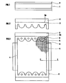
- the entire silicone strip and its polyester support film were cut by punching into four contiguous elements (FIGS. 2 and 3), two transverse elements (3) for internal sealing of the orifices corresponding to the orifices of the membrane bags. ( Figure 2) and two longitudinal elements (4) used with the previous sealing of the periphery.
- the elements (3) and (4) are contiguous and provide a continuous peripheral border. Their junction lines such as (6) will disappear after the treatment, the grid (5) equipped then becoming an intermediate support (11) according to the invention.
- FIG. 4 shows the arrangement of the stack obtained: above the work surface (7), there is successively the grid (5) made of polyamide, the element of raw silicone (4) and its polyester support film ( 2), which extends beyond the silicone (4) towards the outside of the grid (5).
- the grid (5) thus equipped was then placed in a heating compression device with two parallel plates (8) and (9), the underside of this grid (5) being protected by a teflon-coated glass cloth (10) (fig 5).
- the treatment applied was 4 min at 120 ° C under pressure.
- the arrangement obtained at the end of the treatment is shown diagrammatically in FIG. 5.
- the thickness of the polymerized silicone (40) is practically unchanged (0.5 mm), but it is distributed for approximately 1/3 below the grid (5 ) and for about 2/3 above the grid.
- the silicone has penetrated into the grid (5) continuously, and the upper face and the lower face of the silicone border obtained (40) are smooth, once the polyester films (2) are detached from the polymerized border, with a variation maximum thickness of 0.02 mm.
Landscapes
- Engineering & Computer Science (AREA)
- Mechanical Engineering (AREA)
- Chemical & Material Sciences (AREA)
- Composite Materials (AREA)
- Robotics (AREA)
- Manufacturing & Machinery (AREA)
- Chemical Kinetics & Catalysis (AREA)
- Separation Using Semi-Permeable Membranes (AREA)
- External Artificial Organs (AREA)
Abstract
Description
- Le procédé de l'invention concerne le domaine de la micro-filtration, qu'il s'agisse d'ultra-filtration, de perméation gazeuse ou d'hémo-dialyse, et il concerne plus précisément la fabrication d'un support intercalaire étanche qui sera placé entre les membranes ou sacs membranaires empilés constituant une unité de filtration
- Le support intercalaire consiste, de façon connue, en une grille perméable, typiquement en polyamide, ayant sur son pourtour des liserés de matériau élastomère, par exemple du silicone.
- Ces liserés doivent jouer un rôle de joint d'étanchéité, à la fois interne et externe pour l'empilage des sacs membranaires serrés mécaniquement. Sur le plan interne, ils entourent les orifices correspondant aux orifices des sacs membranaires empilés, orifices servant à la circulation du fluide à filtrer dans ces sacs membranaires et dont l'étanchéité est importante pour l'efficacité et la qualité de la filtration. Sur le plan externe, les liserés doivent assurer l'étanchéité aussi bien sur les deux bords des sacs membranaires empilés ne comportant pas d'orifices que sur les deux bords portant les orifices précédents.
- Les techniques traditionnelles de fabrication de tels supports intercalaires aboutissent à des liserés de contour irrégulier et surtout d'épaisseur irrégulière. Ces supports donnent-une étanchéité déficiente pour les sacs membranaires empilés et serrés, et la coutume est d'utiliser de la colle pour pallier ces insuffisances d'étanchéité. Cette colle se répand à l'intérieur des sacs membranaires, en obstruant partiellement les canaux de communication et les surfaces de filtration.
- Le problème que se propose de résoudre l'invention est l'obtention de supports intercalaires ayant des liserés conduisant à l'étanchéité sans adjonction de colle, ces liserés ayant accessoirement un contour bien régulier.
- La demanderesse ne connaît pas de document antérieur concernant le procédé de fabrication de tels supports intercalaires.
- Un procédé typique consiste en un surmoulage de silicone sur la grille de polyamide suivi d'une polymérisation. Le moule ferme difficilement en tous points, et il se produit des échappements de silicone vers l'intérieur de la grille ainsi que des défauts de planéité ou des variations d'épaisseur des liserés conduisant aux défauts d'étanchéité mentionnés.
- Pour réaliser des liserés réguliers et étanches, la demanderesse a eu l'idée de remplacer le surmoulage par un transfert suivi d'un traitement de pénétration. L'élastomère cru étant déformé au moindre contact, on utilise un support-transfert qui permet de recueillir un ruban régulier d'élastomère cru,typiquement à la sortie d'une extrudeuse, puis de le découper selon le contour dessiné, puis de l'appliquer avec son support sur la grille perméable, la pénétration dans la grille et la polymérisation se faisant ensuite entre des surfaces parallèles. Et, de façon surprenante, le liseré obtenu est continu et lisse aussi bien sur la face de la grille sur laquelle l'élastomère a été appliqué que sur l'autre face. Les supports intercalaires obtenus permettent alors de constituer des cassettes ou unités de filtration étanches par simple serrage, sans emploi de colle.
- De façon plus précise, le procédé de l'invention comprend essentiellement les étapes successives suivantes :
- a) on dépose un film d'élastomère cru sur un support-transfert;
- b) on découpe l'ensemble obtenu en un élément ayant, en ce qui concerne l'élastomère, la géométrie du liseré, ou en plusieurs éléments réalisant par application bout à bout cette géométrie;
- c) on applique ce ou ces éléments sur une face de la grille perméable, le matériau élastomère étant tourné vers la grille;
- d) on traite la grille ainsi équipée en pression et à température comprise entre 100 et 150° C pour faire pénétrer l'élastomère dans la grille et le polymériser, le réglage (temps, température) étant tel qu'on obtient de chaque côté de la grille une surface de liseré parfaitement lisse, permettant une jonction étanche;
- e) on extrait le support-intercalaire du dispositif de traitement et on détache de son liseré le (ou les) supports-transferts.
- Les caractéristiques préférentielles suivantes s'appliquent à-ce procédé, individuellement ou selon les diverses combinaisons possibles ;
- - le support-transfert est un film de polyester, d'épaisseur typiquement comprise entre 0,02 et 0,05 mm;
- - le matériau élastomère est du silicone;
- - (selon l'étape a), on dépose un film de silicone cru brut d'extrusion, donc calibré par cette extrusion, sur un film en polyester;
- - ce film de silicone cru a une épaisseur constante comprise entre 0,2 et 0,6 mm, ou encore de préférence comprise entre 0,4 et 0,6 mm;
- - la grille perméable utilisée est en polyamide;
- - on traite la grille équipée d'élément (1) en élastomère cru sur support(s)-transfert en pression et à température comprise entre 110 et 130° C pendant 1 à 5 mn.
- Le traitement en pression et en température (étape d) peut être effectué entre 2 plateaux parallèles. s'il s'agit de plateaux en-métal, on protégera de préférence la face inférieure de la grille, face non garnie d'élastomère en début d'opération, par exemple par un tissu téflonné ou par un film de polyester, pour éviter le collage de l'éJastomère au plateau inférieur en fin de traitement. La face supérieure du 'liseré d'élastomère est, elle, protégée vis-à-vis du collage, par son support transfert, qui sera détaché facilement du liseré après le traitement (étape e).
- On peut aussi envisager d'utiliser un dispositif de calandrage pour réaliser l'application du film d'élastomère sur la grille, puis sa pénétration et sa polymérisation. En ce qui concerne la pénétration de l'élastomère dans la grille par pression, elle se fait par serrage des cylindres entre lesquels la grille se déplace de façon continue. Les liserés longitudinaux sont réalisés en une opération, les conditions de temps et de température nécessaires pour la polymérisation étant réalisées par l'ensemble du dispositif de calandrage. Les liserés transversaux sont ensuite réalisés en reprise, en déposant les éléments transversaux complétant le liseré d'étanchéité et en traitant à nouveau la grille en pression et en température, ce qui est sans inconvénient pour les liserés déjà polymérisés.
- Cette reprise est faite soit en faisant une application des liserés transversaux sur la grille suivie d'un traitement entre deux plateaux parallèles, soit au moyen d'un dispositif de calandrage qui peut être le même.
- Le procédé utilisant au moins en partie un dispositif de calandrage permet de réaliser soit des supports intercalaires de grande longueur, soit des supports intercalaires fabriqués en série.
- Les films d'élastomère prédéposés sur support-transfert peuvent être interrompus de façon à permettre la découpe en grilles individuelles après le premier calandrage, et l'application dans les espaces réservés d'éléments de liseré transversaux.
- Par rapport aux supports intercalaires de l'art antérieur, les supports de l'invention se distinguent par la géométrie de leurs liserés, dont le contour régulier ne dépend que de l'outillage de découpe et dont l'épaisseur varie très peu et surtout de façon progressive (pas de défauts localisés), la variation totale d'épaisseur du liseré d'un support ne dépassant pas 0,05 mm pour une épaisseur totale de liseré comprise entre 0,4 et 0,6 mm.
- L'exemple qui suit et les schémas qui l'illustrent permettent de mieux comprendre l'invention.
- La figure 1 représente un film de silicone déposé sur un support-transfert, en vue de dessus.
- La figure 2 représente l'ensemble obtenu après découpe, en vue de dessus.
- La figure 3 représente une grille équipée d'un liseré en élastomère, composé de quatre éléments jointifs surmontés de leurs supports-transfert, en vue de dessus, ainsi que le support intercalaire obtenu après le traitement.
- La figure 4 est un schéma d'empilement selon une coupe transversale selon le plan I-I repéré sur la figure 3.
- La figure 5 est un schéma similaire, en coupe transversale, entre les deux plateaux parallèles du dispositif de traitement, à la fin du traitements
- On a fabriqué une série de supports intercalaires en partant de grilles perméables d'épaisseur 0,3 mm en polyamide et de silicone cru extrudé en bande (1) de largeur 34 mm et d'épaisseur 0,5 mm déposée sur un film en polyes-1 ter (2) servant de support-transfert (figure 1).
- De telles grillea en polyamide ne se déforment qu'à plus de 150° C, ce qui permettra d'appliquer sur les grilles équipées le traitement thermique de l'invention. Ce qui suit relate la fabrication d'un seul support intercalaire.
- On a découpé, par poinçonnage, l'ensemble de la bande silicone et de son film support en polyester en quatre éléments jointifs (figures 2 et 3), deux éléments transversaux (3) d'étanchéité interne des orifices correspondant aux orifices des sacs membranaires (figure 2) et deux éléments longitudinaux (4) servant avec les précédents à l'étanchéité du pourtour. Les éléments (3) ayant un bord rectiligne (3a), on a utilisé pour lui le bord de la bande extrudée (1) sans faire de nouvelle découpe, de sorte que le film en polyester (1) non recouvert subsiste au-delà du bord (3a).
- Puis on a appliqué (figure 3) les quatre éléments (3) et (4) sur une grille rectangulaire (5) de 164 x 192 mm, préalablement percée près de chaque bord transversal (borda de 164 mm de long) d'orifices circulaires régulièrement espacés correspondant aux orifices des sacs membranaires.
- )Lea éléments (3) et (4) sont jointifs et réalisent un liseré périphérique continu. Leurs lignes de jonction telles que (6) disparaîtront après le traitement, la grille (5) équipée devenant alors un support intercalaire (11) selon l'invention.
- La figure 4 montre la disposition de l'empilage obtenu : au-dessus du plan de travail (7), on a successivement la grille (5) en polyamide, l'élément en silicone cru (4) et son film support en polyester (2), qui se prolonge au-delà du silicone (4) vers l'extérieur de la grille (5).
- La grille (5) ainsi équipée a ensuite été placée dans un dispositif de compression chauffant à deux plateaux parallèles (8) et (9), le dessous de cette grille (5) étant protégé par une toile de verre téflonnée (10) (fig. 5).
- Le traitement appliqué a été de 4 mn à 120° C sous pression.
- La disposition obtenue en fin de traitement est schématisée sur la figure 5. L'épaisseur du silicone polymérisé (40) est pratiquement inchangée (0,5 mm), mais elle se répartit pour environ 1/3 en-dessous de la grille (5) et pour environ 2/3 au-desus de la grille. Le silicone a pénétré dans la grille (5) de façon continue, et la face supérieure et la face inférieure du liseré en silicone obtenu (40) sont lisses, une fois les films en polyester (2) détachés du liseré polymérisé, avec une variation maximale d'épaisseur de 0,02 mm.
- On a ensuite utilisé 10 supports intercalaires (11) fabriqués de la même façon, pour constituer une unité ou cassette de filtration de 11 sacs membranaires (0,5 m2 de filtration). Après serrage et mise en service, sans emploi de colle, on a constaté qu'il n'y avait pas de fuite.
Claims (9)
Applications Claiming Priority (2)
| Application Number | Priority Date | Filing Date | Title |
|---|---|---|---|
| FR8502990 | 1985-02-20 | ||
| FR8502990A FR2577434B1 (fr) | 1985-02-20 | 1985-02-20 | Procede de fabrication d'un support intercalaire de membranes semi-permeables |
Publications (2)
| Publication Number | Publication Date |
|---|---|
| EP0192593A1 true EP0192593A1 (fr) | 1986-08-27 |
| EP0192593B1 EP0192593B1 (fr) | 1988-05-18 |
Family
ID=9316749
Family Applications (1)
| Application Number | Title | Priority Date | Filing Date |
|---|---|---|---|
| EP86420049A Expired EP0192593B1 (fr) | 1985-02-20 | 1986-02-17 | Procédé de fabrication d'un support intercalaire de membranes semi-perméables |
Country Status (4)
| Country | Link |
|---|---|
| US (1) | US4701234A (fr) |
| EP (1) | EP0192593B1 (fr) |
| DE (1) | DE3660196D1 (fr) |
| FR (1) | FR2577434B1 (fr) |
Cited By (4)
| Publication number | Priority date | Publication date | Assignee | Title |
|---|---|---|---|---|
| FR2642985A1 (fr) * | 1989-02-13 | 1990-08-17 | Asahi Chemical Ind | Garniture d'etancheite destinee a etre utilisee dans un appareil d'electrodialyse |
| FR2662114A1 (fr) * | 1990-05-15 | 1991-11-22 | Eurodia Sa | Procede de fabrication d'un cadre separateur pour empilement dans un dispositif d'echange. |
| FR2705250A1 (fr) * | 1993-05-18 | 1994-11-25 | Eivs Sa | Dispositif d'échange à membranes et à multiples circuits de fluides, et cadre séparateur utile dans un tel dispositif. |
| EP2039963A1 (fr) * | 2007-09-19 | 2009-03-25 | Carl Freudenberg KG | Plaque de séparateur |
Families Citing this family (10)
| Publication number | Priority date | Publication date | Assignee | Title |
|---|---|---|---|---|
| DE4234816C1 (de) * | 1992-10-15 | 1993-10-07 | Seitz Filter Werke | Textilverstärkte Membran und Verfahren zu deren Herstellung |
| JP3980831B2 (ja) | 1998-03-06 | 2007-09-26 | ハーラルト・オーバードルファー | トレー |
| JP3721883B2 (ja) * | 1999-09-22 | 2005-11-30 | 栗田工業株式会社 | 電気脱イオン装置 |
| US20060125187A1 (en) * | 2000-06-21 | 2006-06-15 | Millipore Corporation | Sealing device for filtration devices |
| ATE498453T1 (de) * | 2001-11-16 | 2011-03-15 | Ionics | Abstandshalter für elektrodialyse mit gefüllten zellen |
| US20050269255A1 (en) * | 2002-04-19 | 2005-12-08 | Attila Herczeg | Shaped flow distribution in filtration cassettes |
| US6986428B2 (en) * | 2003-05-14 | 2006-01-17 | 3M Innovative Properties Company | Fluid separation membrane module |
| CN1787872A (zh) * | 2003-05-15 | 2006-06-14 | 米利波尔公司 | 过滤组件 |
| US7279215B2 (en) * | 2003-12-03 | 2007-10-09 | 3M Innovative Properties Company | Membrane modules and integrated membrane cassettes |
| US11092977B1 (en) | 2017-10-30 | 2021-08-17 | Zane Coleman | Fluid transfer component comprising a film with fluid channels |
Citations (6)
| Publication number | Priority date | Publication date | Assignee | Title |
|---|---|---|---|---|
| US2663905A (en) * | 1951-09-06 | 1953-12-29 | Us Rubber Co | Superimposed multiple cavity mold |
| FR2044570A5 (fr) * | 1969-05-27 | 1971-02-19 | Rhone Poulenc Sa | |
| FR1603630A (en) * | 1968-12-13 | 1971-05-10 | Twin fluid exchange unit | |
| US3679059A (en) * | 1968-07-05 | 1972-07-25 | William Boby & Co Ltd | Membrane packs |
| EP0045073A1 (fr) * | 1980-07-24 | 1982-02-03 | Terumo Corporation | Dispositif pour filtrer un liquide du corps |
| DE3103464A1 (de) * | 1981-02-02 | 1982-08-05 | Gkss - Forschungszentrum Geesthacht Gmbh, 2054 Geesthacht | Dichtungsrahmen fuer elektrodialyse-membranstapel |
Family Cites Families (7)
| Publication number | Priority date | Publication date | Assignee | Title |
|---|---|---|---|---|
| NL133652C (fr) * | 1967-03-01 | 1900-01-01 | ||
| US3619323A (en) * | 1968-11-06 | 1971-11-09 | Dow Corning | Method of bonding silicones to silicones |
| DE2356028C3 (de) * | 1973-11-09 | 1978-04-13 | Ewald Doerken Ag, 5804 Herdecke | Plane mit gelochtem Verstärkungsrand sowie Verfahren zu deren Herstellung |
| US4082071A (en) * | 1976-02-20 | 1978-04-04 | Jones Oscar F | Engine vent vapor filter and method of constructing same |
| US4227953A (en) * | 1977-12-02 | 1980-10-14 | Cambridge Filter Corp. | Method of fabricating air filters |
| GB1603519A (en) * | 1978-01-23 | 1981-11-25 | Process Scient Innovations | Filter elements for gas or liquid and methods of making such filters |
| US4264447A (en) * | 1979-06-26 | 1981-04-28 | Dorr-Oliver Incorporated | Ultrafiltration membrane assembly and bonding process therefor |
-
1985
- 1985-02-20 FR FR8502990A patent/FR2577434B1/fr not_active Expired
-
1986
- 1986-02-17 EP EP86420049A patent/EP0192593B1/fr not_active Expired
- 1986-02-17 DE DE8686420049T patent/DE3660196D1/de not_active Expired
- 1986-04-10 US US06/850,114 patent/US4701234A/en not_active Expired - Fee Related
Patent Citations (6)
| Publication number | Priority date | Publication date | Assignee | Title |
|---|---|---|---|---|
| US2663905A (en) * | 1951-09-06 | 1953-12-29 | Us Rubber Co | Superimposed multiple cavity mold |
| US3679059A (en) * | 1968-07-05 | 1972-07-25 | William Boby & Co Ltd | Membrane packs |
| FR1603630A (en) * | 1968-12-13 | 1971-05-10 | Twin fluid exchange unit | |
| FR2044570A5 (fr) * | 1969-05-27 | 1971-02-19 | Rhone Poulenc Sa | |
| EP0045073A1 (fr) * | 1980-07-24 | 1982-02-03 | Terumo Corporation | Dispositif pour filtrer un liquide du corps |
| DE3103464A1 (de) * | 1981-02-02 | 1982-08-05 | Gkss - Forschungszentrum Geesthacht Gmbh, 2054 Geesthacht | Dichtungsrahmen fuer elektrodialyse-membranstapel |
Cited By (5)
| Publication number | Priority date | Publication date | Assignee | Title |
|---|---|---|---|---|
| FR2642985A1 (fr) * | 1989-02-13 | 1990-08-17 | Asahi Chemical Ind | Garniture d'etancheite destinee a etre utilisee dans un appareil d'electrodialyse |
| FR2662114A1 (fr) * | 1990-05-15 | 1991-11-22 | Eurodia Sa | Procede de fabrication d'un cadre separateur pour empilement dans un dispositif d'echange. |
| EP0457676A3 (en) * | 1990-05-15 | 1992-03-11 | Eurodia S.A. | Process for the manufacture of a separator plate for a stack in an exchange device |
| FR2705250A1 (fr) * | 1993-05-18 | 1994-11-25 | Eivs Sa | Dispositif d'échange à membranes et à multiples circuits de fluides, et cadre séparateur utile dans un tel dispositif. |
| EP2039963A1 (fr) * | 2007-09-19 | 2009-03-25 | Carl Freudenberg KG | Plaque de séparateur |
Also Published As
| Publication number | Publication date |
|---|---|
| DE3660196D1 (en) | 1988-06-23 |
| US4701234A (en) | 1987-10-20 |
| FR2577434B1 (fr) | 1987-07-03 |
| FR2577434A1 (fr) | 1986-08-22 |
| EP0192593B1 (fr) | 1988-05-18 |
Similar Documents
| Publication | Publication Date | Title |
|---|---|---|
| EP0192593B1 (fr) | Procédé de fabrication d'un support intercalaire de membranes semi-perméables | |
| EP0457676B1 (fr) | Procédé de fabrication d'un cadre séparateur pour un empilement dans un dispositif d'échange | |
| FR2666519A1 (fr) | Module et dispositif de filtration pour separer et filtrer des fluides selon la methode a ecoulement transversal et procede pour fabriquer le module. | |
| EP1029663B1 (fr) | Procédé et dispositif de laminage de vitrages feuilletés | |
| FR2551025A1 (fr) | Procede pour former un element support particulierement destine a des applications d'emballage sous vide, element support ainsi produit et emballage sous vide comprenant un tel element support | |
| FR2729328A1 (fr) | Stratifie de barriere d'infiltration d'air et procede de fabrication | |
| US9566772B2 (en) | Methods for making a plurality of filter assemblies | |
| FR2730421A1 (fr) | Assemblage a membrane supportee, son procede de preparation et ses methodes d'utilisation | |
| EP0920376B1 (fr) | Procede de fabrication d'un vitrage en verre feuillete et dispositif pour l'execution de ce procede | |
| JPH0214721A (ja) | 膜アセンブリーのための排液ディスク | |
| CN102743911A (zh) | 流体处理设备及流体处理设备的制造方法 | |
| EP0811481B1 (fr) | Procédé pour la fabrication d'un vitrage feuilleté réfléchissant le rayonnement infrarouge pour automobiles | |
| FR2642985A1 (fr) | Garniture d'etancheite destinee a etre utilisee dans un appareil d'electrodialyse | |
| EP0560677B1 (fr) | Vitrage en verre feuilleté chauffable équipé de fils de résistance agencés dans la couche thermoplastique intermédiaire | |
| CH691710A5 (fr) | Procédé de fabrication d'un lot de cellules lamellaires et cellules lamellaires ainsi obtenues. | |
| JP2019520976A (ja) | 一体化ラミネーションストリップを有するスペーサーフィルム | |
| FR2548440A1 (fr) | Film metallise pour la realisation de condensateurs et procede de fabrication desdits condensateurs | |
| EP0117184A1 (fr) | Structure ajourée en matériau déployé, filtre et échangeur thermique comprenant une telle structure, procédé de réalisation d'une structure ajourée en matériau déployé et outil pour la mise en oeuvre de ce procédé | |
| TWI774888B (zh) | 平膜元件及其製造方法 | |
| FR2530690A1 (fr) | Dispositif egoutteur pour eliminer l'eau d'une feuille continue sur une machine a table plate | |
| EP1106231A1 (fr) | Filtre à air, procédé de réalisation d'un tel filtre et installation de mise en oeuvre | |
| JP2006247629A (ja) | スパイラル型膜エレメント及びその製造方法 | |
| US11535531B2 (en) | Reduced lateral leakage in reverse osmosis devices | |
| JP2020054989A (ja) | フィルタエレメント及びフィルタエレメントを備えるフィルタモジュール | |
| EP4717454A1 (fr) | Dispositif amélioré pour isolation thermique et procédé de fabrication |
Legal Events
| Date | Code | Title | Description |
|---|---|---|---|
| PUAI | Public reference made under article 153(3) epc to a published international application that has entered the european phase |
Free format text: ORIGINAL CODE: 0009012 |
|
| AK | Designated contracting states |
Kind code of ref document: A1 Designated state(s): DE FR GB IT SE |
|
| 17P | Request for examination filed |
Effective date: 19861105 |
|
| 17Q | First examination report despatched |
Effective date: 19871022 |
|
| GRAA | (expected) grant |
Free format text: ORIGINAL CODE: 0009210 |
|
| AK | Designated contracting states |
Kind code of ref document: B1 Designated state(s): DE FR GB IT SE |
|
| ITF | It: translation for a ep patent filed | ||
| REF | Corresponds to: |
Ref document number: 3660196 Country of ref document: DE Date of ref document: 19880623 |
|
| GBT | Gb: translation of ep patent filed (gb section 77(6)(a)/1977) | ||
| PLBE | No opposition filed within time limit |
Free format text: ORIGINAL CODE: 0009261 |
|
| STAA | Information on the status of an ep patent application or granted ep patent |
Free format text: STATUS: NO OPPOSITION FILED WITHIN TIME LIMIT |
|
| 26N | No opposition filed | ||
| ITTA | It: last paid annual fee | ||
| EAL | Se: european patent in force in sweden |
Ref document number: 86420049.8 |
|
| PGFP | Annual fee paid to national office [announced via postgrant information from national office to epo] |
Ref country code: GB Payment date: 19960119 Year of fee payment: 11 Ref country code: DE Payment date: 19960119 Year of fee payment: 11 |
|
| PGFP | Annual fee paid to national office [announced via postgrant information from national office to epo] |
Ref country code: SE Payment date: 19960122 Year of fee payment: 11 |
|
| PGFP | Annual fee paid to national office [announced via postgrant information from national office to epo] |
Ref country code: FR Payment date: 19960209 Year of fee payment: 11 |
|
| REG | Reference to a national code |
Ref country code: FR Ref legal event code: CA |
|
| REG | Reference to a national code |
Ref country code: GB Ref legal event code: 732E |
|
| PG25 | Lapsed in a contracting state [announced via postgrant information from national office to epo] |
Ref country code: GB Effective date: 19970217 |
|
| PG25 | Lapsed in a contracting state [announced via postgrant information from national office to epo] |
Ref country code: SE Effective date: 19970218 |
|
| GBPC | Gb: european patent ceased through non-payment of renewal fee |
Effective date: 19970217 |
|
| PG25 | Lapsed in a contracting state [announced via postgrant information from national office to epo] |
Ref country code: FR Effective date: 19971030 |
|
| PG25 | Lapsed in a contracting state [announced via postgrant information from national office to epo] |
Ref country code: DE Effective date: 19971101 |
|
| EUG | Se: european patent has lapsed |
Ref document number: 86420049.8 |
|
| REG | Reference to a national code |
Ref country code: FR Ref legal event code: ST |
|
| PG25 | Lapsed in a contracting state [announced via postgrant information from national office to epo] |
Ref country code: IT Free format text: LAPSE BECAUSE OF NON-PAYMENT OF DUE FEES;WARNING: LAPSES OF ITALIAN PATENTS WITH EFFECTIVE DATE BEFORE 2007 MAY HAVE OCCURRED AT ANY TIME BEFORE 2007. THE CORRECT EFFECTIVE DATE MAY BE DIFFERENT FROM THE ONE RECORDED. Effective date: 20050217 |