EP0192448B1 - Magnetic tape recording and/or reproducing apparatus - Google Patents
Magnetic tape recording and/or reproducing apparatus Download PDFInfo
- Publication number
- EP0192448B1 EP0192448B1 EP86301088A EP86301088A EP0192448B1 EP 0192448 B1 EP0192448 B1 EP 0192448B1 EP 86301088 A EP86301088 A EP 86301088A EP 86301088 A EP86301088 A EP 86301088A EP 0192448 B1 EP0192448 B1 EP 0192448B1
- Authority
- EP
- European Patent Office
- Prior art keywords
- tape
- gear
- motor
- magnetic tape
- operating mode
- Prior art date
- Legal status (The legal status is an assumption and is not a legal conclusion. Google has not performed a legal analysis and makes no representation as to the accuracy of the status listed.)
- Expired - Lifetime
Links
Images


Classifications
-
- G—PHYSICS
- G11—INFORMATION STORAGE
- G11B—INFORMATION STORAGE BASED ON RELATIVE MOVEMENT BETWEEN RECORD CARRIER AND TRANSDUCER
- G11B15/00—Driving, starting or stopping record carriers of filamentary or web form; Driving both such record carriers and heads; Guiding such record carriers or containers therefor; Control thereof; Control of operating function
- G11B15/02—Control of operating function, e.g. switching from recording to reproducing
- G11B15/03—Control of operating function, e.g. switching from recording to reproducing by using counters
-
- G—PHYSICS
- G11—INFORMATION STORAGE
- G11B—INFORMATION STORAGE BASED ON RELATIVE MOVEMENT BETWEEN RECORD CARRIER AND TRANSDUCER
- G11B15/00—Driving, starting or stopping record carriers of filamentary or web form; Driving both such record carriers and heads; Guiding such record carriers or containers therefor; Control thereof; Control of operating function
- G11B15/60—Guiding record carrier
- G11B15/66—Threading; Loading; Automatic self-loading
- G11B15/665—Threading; Loading; Automatic self-loading by extracting loop of record carrier from container
- G11B15/6653—Threading; Loading; Automatic self-loading by extracting loop of record carrier from container to pull the record carrier against drum
- G11B15/6656—Threading; Loading; Automatic self-loading by extracting loop of record carrier from container to pull the record carrier against drum using two-sided extraction, i.e. "M-type"
-
- G—PHYSICS
- G11—INFORMATION STORAGE
- G11B—INFORMATION STORAGE BASED ON RELATIVE MOVEMENT BETWEEN RECORD CARRIER AND TRANSDUCER
- G11B15/00—Driving, starting or stopping record carriers of filamentary or web form; Driving both such record carriers and heads; Guiding such record carriers or containers therefor; Control thereof; Control of operating function
- G11B15/02—Control of operating function, e.g. switching from recording to reproducing
- G11B15/10—Manually-operated control; Solenoid-operated control
-
- G—PHYSICS
- G11—INFORMATION STORAGE
- G11B—INFORMATION STORAGE BASED ON RELATIVE MOVEMENT BETWEEN RECORD CARRIER AND TRANSDUCER
- G11B15/00—Driving, starting or stopping record carriers of filamentary or web form; Driving both such record carriers and heads; Guiding such record carriers or containers therefor; Control thereof; Control of operating function
- G11B15/18—Driving; Starting; Stopping; Arrangements for control or regulation thereof
- G11B15/1883—Driving; Starting; Stopping; Arrangements for control or regulation thereof for record carriers inside containers
-
- G—PHYSICS
- G11—INFORMATION STORAGE
- G11B—INFORMATION STORAGE BASED ON RELATIVE MOVEMENT BETWEEN RECORD CARRIER AND TRANSDUCER
- G11B15/00—Driving, starting or stopping record carriers of filamentary or web form; Driving both such record carriers and heads; Guiding such record carriers or containers therefor; Control thereof; Control of operating function
- G11B15/18—Driving; Starting; Stopping; Arrangements for control or regulation thereof
- G11B15/26—Driving record carriers by members acting directly or indirectly thereon
- G11B15/28—Driving record carriers by members acting directly or indirectly thereon through rollers driving by frictional contact with the record carrier, e.g. capstan; Multiple arrangements of capstans or drums coupled to means for controlling the speed of the drive; Multiple capstan systems alternately engageable with record carrier to provide reversal
- G11B15/29—Driving record carriers by members acting directly or indirectly thereon through rollers driving by frictional contact with the record carrier, e.g. capstan; Multiple arrangements of capstans or drums coupled to means for controlling the speed of the drive; Multiple capstan systems alternately engageable with record carrier to provide reversal through pinch-rollers or tape rolls
-
- G—PHYSICS
- G11—INFORMATION STORAGE
- G11B—INFORMATION STORAGE BASED ON RELATIVE MOVEMENT BETWEEN RECORD CARRIER AND TRANSDUCER
- G11B15/00—Driving, starting or stopping record carriers of filamentary or web form; Driving both such record carriers and heads; Guiding such record carriers or containers therefor; Control thereof; Control of operating function
- G11B15/60—Guiding record carrier
- G11B15/66—Threading; Loading; Automatic self-loading
- G11B15/665—Threading; Loading; Automatic self-loading by extracting loop of record carrier from container
-
- G—PHYSICS
- G11—INFORMATION STORAGE
- G11B—INFORMATION STORAGE BASED ON RELATIVE MOVEMENT BETWEEN RECORD CARRIER AND TRANSDUCER
- G11B15/00—Driving, starting or stopping record carriers of filamentary or web form; Driving both such record carriers and heads; Guiding such record carriers or containers therefor; Control thereof; Control of operating function
- G11B15/675—Guiding containers, e.g. loading, ejecting cassettes
- G11B15/67544—Guiding containers, e.g. loading, ejecting cassettes with movement of the cassette parallel to its main side and subsequent movement perpendicular thereto, i.e. front loading
- G11B15/67547—Guiding containers, e.g. loading, ejecting cassettes with movement of the cassette parallel to its main side and subsequent movement perpendicular thereto, i.e. front loading the two movements being made by the cassette holder
- G11B15/67549—Guiding containers, e.g. loading, ejecting cassettes with movement of the cassette parallel to its main side and subsequent movement perpendicular thereto, i.e. front loading the two movements being made by the cassette holder with servo control
Definitions
- This invention relates to a magnetic tape recording and/or reproducing (MTRR) apparatus of the automatic tape-loading and -unloading type such as a video cassette recorder and an audio tape recorder, wherein a magnetic tape is drawn out of a tape cassette and wound at a predetermined angle around a guide drum positioned outside the tape cassette and carrying a magnetic head for recording and/or reproducing signals on/from the magnetic tape.
- MTRR magnetic tape recording and/or reproducing
- Japanese Laid-Open Patent Application No. 56-114154 discloses a construction which drives with one motor both operating mode changing means for changing conditions of the MTRR apparatus and tape loading means for drawing a magnetic tape out of a tape cassette and winding it at a predetermined angle around a guide drum carrying a rotary magnetic head.
- EP-A2-0087952 discloses a magnetic tape recording and/or reproducing apparatus provided with a reversible motor for driving the operating mode changing means and the tape loading means, whereas the reel turntables are driven by the capstan.
- An object of this invention is to provide a MTRR apparatus which performs with one motor the cassette loading operation, the tape loading operation, the operating mode changing operation and the magnetic tape transporting operation.
- a MTRR apparatus which uses a tape cassette having therein tape reels on which a magnetic tape is wound and comprises: a capstan for transporting said magnetic tape at a constant speed in cooperation with a pinch roller; a motor for rotatably driving said capstan; cassette loading means for loading said tape cassette at a predetermined position; tape loading means reciprocating between an inoperative position where said magnetic tape is within said tape cassette and an operative position where said magnetic tape is drawn out of said tape cassette to be loaded in a specific tape path; operating mode changing means for changing operating mode of said apparatus from one operating mode to another; a pair of reel turntables engageable with said tape reels for rotating said tape reels; reel turntable driving means for transmitting a driving force of said motor to said reel turntables; and characterized by clutch means for intermittently transmitting the driving force of said motor to said cassette loading means, said tape loading means and said operating mode changing means, whereby cassette loading operation, tape loading operation, operating mode changing operation and magnetic tape transporting operation are performed by said motor.
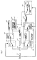
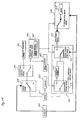
- Fig. 1 is a block diagram showing an embodiment of a MTRR apparatus according to this invention.
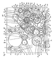
- Fig. 2 is a schematic plan view of the embodiment, in which the position of a tape cassette is indicated by dot-dash lines, in a stopping mode, a fast-forward-winding mode, or a recording/reproducing mode.
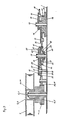
- Fig. 3 is a schematic sectional view of a mechanism of a reel turntable driving means.
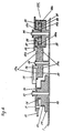
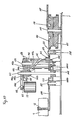
- Fig. 4 is a schematic sectional view of a mechanism including a selectively driving means, a tape loading means, and a controlling torque means.
- Figs. 5A, 5B and 5C are diagrams showing relationships between the amount of cam lift and degree of cam rotation.
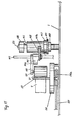
- Figs. 6A and 6B are schematic sectional views of a mechanism including a clutch means, the selectively driving means and an operating mode changing means.
- Fig. 7 is a perspective view of a mechanism of the clutch means.
- Fig. 8 is a schematic sectional view of a mechanism including the operating mode changing means, a controlling brake means and a intermittently rotating means.
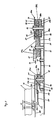
- Fig. 9 is a schematic sectional view of a mechanism including the selectively driving means and the tape loading means.
- Fig. 10 is a schematic sectional view of a mechanism of a pinch roller press-contact means.
- Fig. 11 is a side view of a mechanism including a motor and a driving member for the pinch roller press-contact means.
- Figs. 12A and 12B are schematic top views of a mechanism of the selectively driving means.
- Fig. 13 is a side view of a mechanism of a cassette loading means.
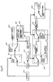
- Fig. 14 is a block diagram of the apparatus in the stopping mode.
- Fig. 15 is a block diagram of the apparatus in the fast-forward-winding mode.
- Fig. 16 is a schematic plan view of the apparatus in the fast-forward-winding mode.
- Fig. 17 is a schematic plan view of the apparatus in the state where a first rotatable disc and a second rotatable disc rotate to a rotary angle of 170°.
- Fig. 18 is a block diagram of the apparatus in the state just before the recording/reproducing mode.
- Fig. 19 is a schematic plan view of the apparatus in the state just before the recording/reproducing mode.
- Fig. 20 is a block diagram of the apparatus in the recording/reproducing mode.
- Figs. 1, 14, 15, 18 and 20 are block diagrams of an embodiment of the invention, in which lines connecting respective means and components show channels of transmitting a rotational driving force of a motor 501, operation of an actuator 500 or operations of respective means to respective means, thick lines showing the state of being transmitting the rotational driving force and/or the operations, thin lines showing the states of being inactivated, and arrows showing the directions of the respective transmissions.
- the rotational driving force of the motor 501 which drives a capstan 502 is transmitted intermittently to a selectively driving means 504 by a clutch means 503.
- the selectively driving means 504 selectively drives either a cassette loading means 505, or an operating mode changing means 506 and a tape loading means 508.
- the operating mode changing means 506 working with the tape loading means 508 comprises a pinch roller press-contact means 507 and controls both an intermittently rotating means 512 and a controlling brake means 514 having a brake 515.
- a reel turntable driving means 509 transmitting the rotational driving force of the motor 501 to a reel turntable 513 has a controlling torque means 510 controlled by the tape loading means 508, a limiting torque means 511 and the intermittently rotating means 512.
- the controlling torque means 510 transmits the rotational driving force of the motor 501 to the intermittently rotating means directly or indirectly through the limiting torque means 511 under the control of the tape loading means 508.
- the reel turntable 513 being intermittently transmitted the rotational driving force of the motor 501 by the intermittently rotating means 512 is selectively braced by the controlling brake means 514.
- the actuator 500 drives and/or control the clutch means 503, the intermittently rotating means 512 and the controlling brake means 514.
- Fig. 2 is a plan view of the embodiment of the invention, in which a supply reel turntable 4 and a take-up reel turntable 5 are fitted freely-rotatably onto shafts 2 and 3 mounted on a chassis 1 and engage with a supply reel hub 7 and a take-up reel hub 8 respectively within a tape cassette 6 mounted at a predetermined position (shown in dot-dash lines) of the apparatus, thereby rotating integrally with the reel hubs 7 and 8.
- the magnetic tape 9 drawn out of the supply reel hub 7 passes by the front surface of the tape cassette 6 and reaches the tape-up reel hub 8.
- Tape guide posts 13, 14 secured on supports 13b and 14b respectively, and a tape guide post 15 for drawing the magnetic tape 9 out of the tape cassette 6 and guiding the magnetic tape 9, are within the respective recesses 10, 11 and 12 and behind the magnetic tape 9.
- Figs. 2, 16, 17 and 19 are plan views of the embodiment of the invention, in which a guide drum 16 having rotary magnetic heads (not shown), a fixed post 17 guiding the magnetic tape 9, a full track erase head 19 erasing all signals recorded on the magnetic tape 9, an audio erase head 20 erasing audio signals recorded on the magnetic tape 9, an audio & control head 21 recording and/or reproducing audio signals and control signals for controlling a tape speed and phase on/from the magnetic tape 9, a capstan 23 transporting the magnetic tape 9 at a constant speed in cooperation with a pinch roller 22, and a motor 24 driving the capstan 23 are disposed on the chassis 1.
- the motor 24 is a brushless motor with less torque variation and its spindle serves for the capstan 23.
- a pulley 28 having toothed portions 26 and 27 is fitted rotatably onto a shaft 25 mounted on the chassis 1, and is rotatably driven by the motor 24 through a belt 29 stretched across the pulley 28 and a pulley 24a press-fitted onto the capstan 23. Also a support plate 30 for changing the reduction ratio between the motor 24 and both of the reel turntables 4 and 5 is supported rotatably to the shaft 25 as shown in Fig. 3.
- a gear 32 used in the recording/reproducing mode is fitted rotatably onto a shaft 31 mounted at one end of the support plate 30 and adapted to always engage with the toothed portion 26 integral with the pulley 28, while a gear 34 used in the fast-forward-winding mode is fitted rotatably onto a shaft 33 mounted at the other end of the support plate 30 and adapted to always engage with the toothed portion 27 integral with the pulley 28.
- a flexible member 35 having at one end of a first cam follower 36 is fixed upon the support plate 30 as shown in Fig. 4.
- the controlling torque means 510 which controls a driving torque of the both reel turntables 4 and 5, comprises the pulley 28, support plate 30, gear 32 and gear 34.
- the first rotatable disc 37 which drives the tape loading means 508, is fitted rotatably onto a shaft 38 mounted on the chassis 1, and has at one side a positive cam of grooved cam 37a engageable with the first cam follower 36 for driving the controlling torque means 510, and at the other side a positive cam of grooved cam 37b for driving the tape loading means 508.
- the grooved cam 37a and 37b extend at an angle of 360° or more as shown in Fig. 5B, and the amount of the cam lift varies between a specific range of degrees of cam rotation.
- a symbol "a” shows a curve of the cam lift for the grooved cam 37a
- a symbol "b” shows a curve of the cam lift for the grooved cam 37b.
- the first cam follower 36 is adapted to move only in a range of rotary angle 70° to 120° of the first rotatable disc 37, in which the first rotatable disc 37 rotates clockwise to move the first cam follower 36 rightwardly in Fig. 2, so that the support plate 30 is swung clockwise around the shaft 25.
- a limiting torque member 40 is supported rotatably to a shaft 39 mounted on the chassis 1 as shown in Fig. 3 and adapted to keep constant the driving torque of the motor 24 transmitted to the both reel turntables 4 and 5.
- the limiting torque member 40 comprises an upside gear 41 of the same diameter as the lower part gear 44, fitted rotatably to the shaft 39, the lower part gear 44 supported rotatably to a boss 43 provided at the upside gear 41, a friction member 42, such as felt material, adhering to the lower surface of the upside gear 41, a compression spring 46 pressing the friction member 42 against an upside surface 45, a spring shoe 47, a thrust plate 48 and a stopper plate 49.
- a turnable arm 50 is also supported rotatably to the shaft 39, and a turnable idler gear 52 always engageable with the lower part gear 44 is fitted rotatably onto a shaft 51 mounted at one end of the turnable arm 50.
- a friction member 53 made of such as a felt material, adheres to the turnable arm 50 and disposed between the turnable arm 50 and an upper surface 57 of the turnable idler gear 52.
- a spring shoe 55 and a stopper plate 56 are supported to the shaft 51 and a compression spring 54 is disposed between the rear surface of the turnable idler gear 52 and the spring shoe 55 for pressing the friction member 53 against the upper surface 57 of the turnable idler gear 52 as shown in Fig. 3.
- the turnable arm 50 When the lower part gear 44 rotates, the turnable arm 50 is turned by the friction between the upper surface 57 of the turnable idler gear 52 and the friction member 53 corresponding to the rotational direction of the lower part gear 44, and allows the turnable idler gear 52 to engage with an idler gear 59 always engageable with a reel gear 58 integral with the take-up reel turntable 5 or an idler gear 61 always engageable with a reel gear 60 integral with the supply reel turntable 4, thereby selectively transmitting the rotation of the motor 24 to the take-up reel turntable 5 or the supply reel turntable 4.
- the gear 34 engageable with the toothed portion 27 integral with the pulley 28 engages with the lower part gear 44 so that the driving torque of the motor 24 is directly transmitted to the both reel turntables 4 and 5 not through the friction member 42 of the limiting torque member 40.
- the support plate 30 turns clockwise around the shaft 25 to disengage the gear 34 from the lower part gear 44, and then allows the gear 32 which engages with the toothed portion 26 integral with the pulley 28 to engage with the upside gear 41, so that more than 120°, the gear 32 engages with the upside gear 41.
- the controlling torque means 510 is driven and controlled by the first rotatable disc 37 which drives the tape loading means 508 to be discussed below.
- the reduction ratio from the upside gear 41 to the reel gear 60 integral with the supply reel turntable 4 is larger than that from the upside gear 41 to the reel gear 58 integral with the take-up reel turntable 5, so as to make the winding torque of the supply reel turntable 4 in the reviewing mode larger than that of the take-up reel turntable 5 in the recording and/or reproducing mode.
- the rotational driving force of the motor 24 (501 in Fig. 1) is transmitted to the first rotatable disc 37, the second rotatable disc 66 and the third rotatable disc 67 respectively through a first idler gear 62 engageable with the toothed portion 27 integral with the pulley 28, a second idler gear 63 engageable with the first idler gear 62, and the clutch gear 65 engageable with both the second idler gear 63 and a first toothed portion 64a integral with a driving gear 64.
- the clutch gear 65 always engageable with the second idler gear 63 is supported rotatably to a shaft 68 mounted on the chassis 1, allowed to move upwardly and downwardly along the shaft 68, always biased downwardly by a compression spring 65a, and disposed on a first clutch plate 69 fitted rotatably onto a shaft 70 mounted on the chassis 1 as shown in Figs. 6A and 6B.
- the first clutch plate 69 has an upper face 69a and a lower face 69b which are different in hight as shown in Figs 6A, 6B and 7.
- a slot 72 provided at a second clutch plate 71 which is fitted rotatably onto the shaft 70 and disposed on the first clutch plate 69, engages with a projection 73 provided at the first clutch plate 69, and a torsion spring 75 is disposed between the projection 73 and a projection 74 provided at the second clutch plate 71 as shown in Fig. 7, so that the second clutch plate 71 is always biased counter-clockwise, as shown in Fig. 2, to allow the first clutch plate 69 and the second clutch plate 71 to turn integrally with each other around the shaft 70.
- the solenoid 81 When the solenoid 81 is energized, the plunger 82 is retracted in the direction of the arrow A in Fig.
- the clutch gear 65 runs onto the upper face 69a from the lower face 69b of the first clutch plate 69 and changed from the condition as shown in Fig. 6A to that as shown in Fig. 6B, so that the clutch gear 65 engages with the first toothed portion 64a integral with the driving gear 64.
- the clutch means 503 is driven and controlled by the actuator 500 comprising the plunger 82 and the solenoid 81.
- the actuator 500 comprises the plunger 82 and the solenoid 81, but it may comprise a motor for obtaining the same effect of this invention.
- the selectively driving means 504 which drives selectively either the cassette loading means 505 or the operating mode changing means 506 comprises a differential gear mechanism 200 as shown in Fig. 6. An explanation will be given on the differential gear mechanism 200.
- the driving gear 64 having the first toothed portion 64a selectively engageable with the clutch gear 65 and a sun gear 64b is fitted freely rotatably onto a shaft 84 mounted on the chassis 1.
- Shafts 86 more than one shaft are provided at a retainer gear 85 which is fitted rotatably onto a boss 64c provided at the driving gear 64, and support rotatably the planetary gears 87 as many as the shafts 86, the planetary gears 87 engaging with the sun gear 64b.
- a transmission gear 88 having at the inner periphery an internal toothed portion 88a and at the outer periphery an external toothed portion 88b is fitted rotatably onto the shaft 84, the internal toothed portion 88a engaging with the planetary gears 87.
- the first rotatable disc 37 for driving the tape loading means 508 engages with the retainer gear 85.
- a second cam follower 91 fixed at one end of an arm 90 supported rotatably onto a shaft 89 mounted on the chassis 1 engages with the grooved cam 37b at the rear surface of the first rotatable disc 37 as shown in Figs. 2 and 9.
- a sector gear 92 formed at the other end of the arm 90 engages with a first loading gear 94 fitted rotatably onto a shaft 93 mounted on the chassis 1.
- a second loading gear 95 integral with the first loading gear 94 and rotatable around the shaft 93 engages with a third loading gear 97 fitted onto a shaft 96 mounted on the chassis 1.
- the loading gear train comprising 94, 95 and 97 rotates in synchronism with the sector gear 92.
- a first arm 98 for rightward loading is fitted rotatably onto the shaft 93.
- a tension spring 99a is stretched between a spring seat 98a provided at the first arm 98 for rightward loading and a pin 95a mounted on the second loading gear 95, so that the pin 95a abuts against a stopper 98b provided at the first arm 98 to allow the first arm 98 and the second loading gear 95 to rotate integrally with each other.
- a second arm 101 for rightward loading is connected rotatably at one end to the end of the first arm 98 through a pin 100 and bore 102 at the other end, the bore 102 being engageable with a pin 14a mounted on the support 14b.
- Reference numeral 103 designates a first arm for leftward loading, which is of the same construction with respect to the third loading gear 97 as between the first arm 98 for rightward loading and the second loading gear 95, thus being integral with the third loading gear 97 through a tension spring 99b (not shown).
- the arm 103 also connects at one end rotatably with a second arm 105 for leftward loading though a pin 104, a bore 106 at the other end of the second arm 105, the bore 106 being engageable with a pin 13a mounted on the support 13b.
- the first arm 98 for rightward loading and the first arm 103 for leftward loading move the supports 14b and 13b to the positions where the tape guide posts 14 and 13 thereof abut against the positioning members 110 and 111 respectively fixed on the sub-chassis 107.
- the first arm 98 for rightward loading and the first arm 103 for leftward loading cannot turn further.
- the second loading gear 95 and the third loading gear 97 continue to rotate counter-clockwise and clockwise against the tension springs 99a and 99b respectively.
- the second rotatable disc 66 engageable with the retainer gear 85 is fitted freely-rotatably onto a shaft 112 mounted on the chassis 1 and has at one side a positive cam of grooved cam 113 extending at an angle of 360° or more as shown in Fig. 5A for changing the operation mode of the apparatus.
- the grooved cam 113 is adapted to move the cam follower 116 only in a range where a lifting amount changes as shown in Fig. 5A.
- the second rotatable disc 66 has the same diameter and the same number of teeth as the first rotatable disc 37.
- a pin 117 fixed at the other end of the turnable arm 115 engages with a slot 119 provided at one end of a main rod 118 which moves to a plurality of positions in synchronism with the movement of the cam follower 116.
- Guide slots 122 and 123 which are cut on the main rod 118 are fitted onto the guide shafts 120 and 121 respectively mounted on the chassis 1, and the main rod 118 is mounted movably in reciprocation along the guide slots 122 and 123.
- the operating mode changing means 506 comprises the grooved cam 113 and the main rod 118.
- Guide slots 196 and 197 which are cut on the sub-rod 130 are fitted onto the guide shafts 194 and 195 respectively mounted on the chassis 1, and the sub-rod 130 is mounted movably in reciprocation along the guide slots 196 and 197.
- a tension spring 199 is stretched between a bore 130c provided at the other end of the sub-rod 130 and a shaft 198 mounted on the chassis 1, so that the sub-rod 130 is always biased leftwardly in Fig. 2 by the tension spring 199.
- a brake 184 at the take-up reel side and that 185 at the supply reel side are fitted rotatably onto the shafts 182 and 183 respectively as shown in Figs. 2 and 8.
- a pin 184a fixed at one end of the brake 184 engages with a slot 187a provided at one end of a brake lever 187 which is fitted rotatably onto a shaft 186 mounted on the chassis 1, thereby the brake 184 at the take-up reel side being adapted to work with the brake lever 187.
- a tension spring 189 is stretched between a pin 187b fixed at the other end of the brake lever 187 and a pin 188 fixed on the sub-rod 130, whereby the brake lever 187 is biased counter-clockwise by the tension spring 189 so that the brake 184 is biased clockwise as shown in Fig. 2.
- a tension spring 191 is stretched between a pin 185a fixed at one end of the brake 185 at the supply reel side and a pin 190 fixed on the sub-rod 130, whereby the brake 185 is biased counter-clockwise by the tension spring 191.
- the brakes 184 and 185 having brake shoes 184b and 185b which abut against the reel turntables 5 and 4 respectively, are made of flexible material thereby being adapted to adjust the braking effect when the brake shoes 184b and 185b tend to bite the reel turntables 5 and 4 respectively.
- Reference numerals 192 and 193 designate kick pins mounted on the brake lever 187 and the supply reel side brake 185 respectively. The brakes 184 and 185 are moved away from the both reel turntables 5 and 4 to release the braking effect, the kick pins 192 and 193 being pushed leftwardly in Fig. 2 by the main rod 118, or the pins 187b and 185a being pushed leftwardly by the sub-rod 130.
- the intermittently rotating means 512 which transmits the rotational driving force of the motor 24 intermittently to both reel turntables 4 and 5 selectively, comprises a righthand stopper arm 126 and a lefthand stopper arm 127 fitted rotatably onto shafts 124 and 125 respectively mounted on the chassis 1.
- a tension spring 133 is stretched between a pin 128 mounted on the righthand stopper arm 126 and a pin 131 mounted on the sub-rod 130, the pin 128 abutting against a notching edge surface 130a provided on the sub-rod 130 to restrain the stopper arm 126 from turning counter-clockwise around the shaft 124.
- a tension spring 134 is stretched likewise between a pin 129 mounted on the lefthand stopper arm 127 and a pin 132 mounted on the sub-rod 130, the pin 129 abutting against a notching edge surface 118a provided on the main rod 118 and/or a notching edge surface 130d provided on the sub-rod 130 to restrain the stopper arm 127 from turning clockwise around the shaft 125.
- the pins 128 and 129 are pushed leftwardly by the notching edge surfaces 130a and 130d respectively, and the both stopper arms 126 and 127 are turned clockwise and counter-clockwise around the shafts 124 and 125 respectively, so that the turnable idler gear 52 is able to engage rotatably either with the idler gear 59 or 61.
- the plunger 82 is retracted in the direction of the arrow A in Fig. 2 instantaneously and the action of the plunger 82 instantaneously returns the sub-rod 130 to the condition of Fig. 2.
- the pins 187b and 185a disengage from the notching edge surfaces 130e and 130f respectively, thereby instantaneously applying the braking effect to the both reel turntables 5 and 4 by the tension springs 189 and 191 respectively.
- the turnable idler gear 52 is disengaged either from the idler gear 59 or 61 by the both stopper arms 126 and 127.
- the action of the plunger 82 by operating the solenoid 81 drives and controls both the intermittently rotating means 512 and the controlling brake means 514.
- the turnable idler gear 52 does not engage rotatably either with the idler gear 59 or 61 regardless of the turnable arm 50 being driven by the motor 24 which transmits its rotation to the turnable arm 50, and the turnable arm 50 turning clockwise or counter-clockwise around the shaft 39, since the shaft 51 mounted on the turnable arm 50 abuts against the edge surface 126a of the righthand stopper arm 126 or that 127a of the lefthand stopper arm 127a.
- the both reel turntables 5 and 4 do not rotate.
- the second rotatable disc 66 rotates clockwise to an angle of 110° as shown in Fig.
- the kick pins 192 and 193 are pushed leftwardly by the notching edge surfaces 118d and 118f respectively, thereby turning clockwise around the shafts 186 and 183 against the biasing force of the tension springs 189 and 191.
- the brake lever 187 turns clockwise around the shafts 186, and the brake 184 at the take-up reel side which engages with the brake lever 187 turns counter-clockwise around the shaft 182, the brake 185 at the supply reel side turning clockwise around the shaft 183.
- the kick pins 192 and 193 continue to turn clockwise until the kick pins 192 and 193 run onto the edge surfaces 118e and 118g respectively which moves the brakes 184 and 185 away from the reel turntables 5 and 4 and where the brake effect is released.
- the pins 187b and 185a move away from the notching edge surfaces 130e and 130f of the sub-rod 130 respectively, and the pins 187b and 185a do not abut against the sub-rod 130 regardless of the rightward or leftward movement of the sub-rod 130, so that the pins 187b and 185a disengage from the sub-rod 130.
- the pin 129 After the pin 129 having run onto the notching edge surface 118b, the pin 129 moves slidably onto the notching edge surface 118b, and the lefthand stopper arm 127 does not further turn in spite of the leftward movement of the main rod 118, so that the biasing force of the tension spring 134 does not increase with the movement of the main rod 118. If the turnable arm 50 turns clockwise at that time, the turnable idler gear 52 engages with the idler gear 61 as stated above, and the take-up reel turntable 5 is also capable of rotating. This condition is kept until a rotary angle of the second rotatable disc 66 becomes 298°.
- the pin 126b turns clockwise around the shaft 124 against the biasing force of the tension spring 133 and continues to turn until the turnable idler gear 52 is engageable with the idler gear 59.
- the rotatable disc 66 rotates to an angle of 323°.
- the turnable idler gear 52 is engageable with the idler gear 59.
- the turnable arm 50 turns counter-clockwise at that time, the turnable idler gear 52 engages with the idler gear 59, and the take-up reel turntable 5 is capable of rotating and winding the magnetic tape 9 onto the take-up reel hub 8.
- the operating mode changing means 506 which comprises the grooved cam 113 and the main rod 118, drives and controls both the intermittently rotating means 512 and the brakes 184 and 185.
- a gear 135 in engagement with the second rotatable disc 66 driving the operating mode changing means 506 is fitted rotatably onto a shaft 136 mounted on the chassis 1 and engages with a toothed portion 139 integral with a driving member 138 which is fitted rotatably onto a shaft 137 mounted on the chassis 1.
- the driving member 138 is provided with a first peripheral cam 140, a cylindrical cam 141 and a second peripheral cam 142.
- the first peripheral cam 140 abuts against a first edge surface 144a of a relay lever 144 which is fitted rotatably onto a shaft 143 mounted on the chassis 1, so that the first peripheral cam 140 pushes the first edge surface 144a.
- the cylindrical cam 141 abuts against a projection 145a of a guide member 145 which is fitted onto the shaft 137, guided by the shaft 137 and capable of moving perpendicularly to the chassis 1, thereby moving the guide member 145 up and down.
- the second peripheral cam 142 abuts against a projection 146a of a pressure lever 146 which presses the pinch roller 22 to be in contact with the capstan 23 after the pinch roller 22 has moved to a predetermined position, so that the second peripheral cam 142 pushes the projection 146a.
- An outer periphery 148a of a pinch roller arm 148 which is fitted rotatably onto the shaft 143 is fitted both onto an interior 146b of the pressure lever 146 and onto a bore 145b provided at one end of the guide member 145, and the pinch roller arm 148 is supported by an upper surface 146c of the pressure lever 146, the pressure lever 146 being supported by an upper surface 145c of the guide member 145.
- the pressure lever 146 and the pinch roller arm 148 move integrally with the guide member 145 upwardly or downwardly in Figs. 10 and 11 guided by the shaft 143, when the guide member 145 moves upwardly or downwardly guided by the shaft 137.
- a tension spring 151 as shown in Fig.
- the pinch roller 22 is fitted freely-rotatably onto a shaft 152 mounted at one end of the pinch roller arm 148 rotating integrally with the pressure lever 146.
- the tape guide post 15 for drawing the magnetic tape 9 out of the tape cassette 6 is fixed at one end of a guide post arm 154 fitted rotatably onto a shaft 153 mounted on the chassis 1, a pin 155 being fixed at the other end of the guide post arm 154 so as to abut against a second edge surface 144b of the relay lever 144.
- the pin 155 is pushed by the second edge surface 144b of the relay lever 144, so that the guide post arm 154 turns around the shaft 153.
- the cylindrical cam 141, the first peripheral cam 140 and the second peripheral cam 142 as shown in Fig.
- FIG. 5C are adapted to vary their amounts of cam lift between a specific range of degrees of cam rotation and symbols “a”, “b” and “c” show the curves of cam lift for the cylindrical cam 141, the first peripheral cam 140 and the second peripheral cam 142 respectively.
- the horizontal axis in Fig. 5C shows a rotary angle of the driving member 138 and the broken lines in Figs. 5A, 5B and 5C show correspondence to a rotary angle of the second rotatable disc 66 which drives the driving member 138 increasingly in speed. For instance, when the second rotatable disc 66 rotates at an angle of 150°, the second rotatable disc 66 drives the driving member 138 rotatably to an angle of 244°.
- the clockwise rotation of the second rotatable disc 66 is transmitted to the driving member 138 through the gear 135, so that the driving member 138 rotates clockwise.
- the driving member 138 rotates to an angle of 277°
- the first edge surface 144a of the relay lever 144 is pushed by the first peripheral cam 140 and the relay lever 144 rotates counter-clockwise around the shaft 143, at which time the second edge surface 144b of the relay lever 144 pushes the pin 155 and the guide post arm 154 rotates clockwise around the shaft 153.
- the tape guide post 15 fixed on the guide post arm 154 draws out the magnetic tape 9 to a predetermined position as shown in Fig. 17, so that the magnetic tape 9 forms a tape path as shown in dot-dash lines in Fig.
- the tape guide post 15 is locked by locking means (not shown).
- the driving member 138 continues its rotation to an angle of 527° as shown in Fig. 5C
- the guide member 145 abutting against the cylindrical cam 141
- the pressure lever 146 and the pinch roller arm 148 move down integrally with each other perpendicularly to the tape path of the magnetic tape 9 along the shaft 143 guided by the cylindrical cam 141
- the pinch roller 22 also moves down perpendicularly to the tape path of the magnetic tape 9 as shown in Fig. 11 from the position where the tape guide post 15 is not hindered from drawing out the magnetic tape 9 as shown in Fig. 10, so as to be positioned inside of the loop of the tape path formed by the tape guide post 15 drawing out the magnetic tape 9 as shown in dot-dash lines in Fig. 17.
- the second rotatable disc 66 which drives the operating mode changing means 506 and the tape loading means 508, and the third rotatable disc 67 which drives the cassette loading means 505 are both fitted rotatably onto the shaft 112 and in engagement with the retainer gear 85 and the transmission gear 88 respectively.
- notching grooves 160 and 161 are provided respectively, into which projection stoppers 158 and 159 are fit, being provided at both ends of a detent arm 157 fitted rotatably onto a shaft 156 mounted on the chassis 1.
- Fig. 12A shows the tape cassette 6 not in the state of being mounted on the apparatus
- Fig. 12B shows the tape cassette 6 in the state of being mounted.
- the motor 24 rotates counter-clockwise to transmit its rotation to the driving gear 64.
- the driving gear 64 starting its counter-clockwise rotation
- the projection stopper 158 of the detent arm 157 enters into the notching groove 160 so as to restrain the second rotatable disc 66 rotating.
- the retainer gear 85 engageable with the second rotatable disc 66 is also restrained from rotating, and the rotation of the driving gear 64 is transmitted through planetary gears 87 to the transmission gear 88 which only starts to rotate clockwise.
- the third gear 67 engageable with the transmission gear 88 rotates counter-clockwise to drive the cassette loading means 505 to be discussed below.
- the tape cassette 6 is locked by the tape cassette locking means (not shown), whereby the rotation of the third rotatable disc 67 is stopped.
- the phase of the third rotatable disc 67 is set up so that the notching groove 161 of the third rotatable disc 67 is positioned opposite to the projection stopper 159 of the detent arm 157 as shown in Fig. 12B.
- the projection stopper 158 gets out of the notching groove 160 by the moment of the clockwise force around the shaft 156 generated by the rotatable driving force of the second rotatable disc 66 through the notching groove 160, so that the detent arm 157 starts turning clockwise around the shaft 156.
- the projection stopper 159 enters into the notching groove 161 opposite to the projection stopper 159, whereby the third rotatable disc 67 is locked.
- the driving gear 64 continues its counter-clockwise rotation, the second rotatable disc 66 only rotates continuously, and the third rotatable disc 67 which drives the cassette loading means 505 holds the state of being locked by the projection stopper 159. In this way, changes are made from the cassette loading means 505 to the operating mode changing means 506 or to the tape loading means 508.
- the driving gear 64 rotates clockwise when the motor 24 reversely rotates clockwise so that the rotational driving force of the motor 24 is transmitted changing from the operating mode changing means 506 or the tape loading means 508 to the cassette loading means 505.
- the second rotatable disc 66 rotating counter-clockwise and the cam follower 116 moving leftwardly, a projection stopper 115b provided on the left side of the turnable arm 115 abuts against a pin 66b fixed on the second rotatable disc 66 to stop the rotation of the second rotatable disc 66 as shown in Fig. 2, at which time the projection stopper 158 and the notching groove 160 are positioned opposite to each other.
- Bosses 164 and 165 provided respectively on the right and left sides of a cassette holder 163 move slidably along guide grooves 168 and 169 provided respectively at a righthand side plate 166 and a lefthand side plate 167 which are disposed upright on either side of the chassis, so that the cassette holder 163 holding the tape cassette 6 moves to mount the tape cassette 6 at the predetermined position of the apparatus.
- Righthand and lefthand wiper arms 170 and 171 in engagement with the bosses 164 and 165 respectively turn around shafts 172 and 173 respectively mounted on both side plates 166 and 167, a toothed portion 174 being provided at the outer periphery of the righthand wiper arm 170.
- the toothed portion 174 engages and rotates with a gear train consisting of gears 175 and 176 and a worm gear 177.
- a gear 178 fitted rotatably onto the same shaft as the worm gear 177 and rotating integrally with the worm gear 177 is geared through a gear 179 to the third rotatable disc 67 which also engages with the transmission gear 88 as shown in Figs. 2 and 6A.
- the transmission gear 88 rotates clockwise and the third gear 67 rotates counter-clockwise, both wiper arms 170 and 171 are consequently driven rotatably clockwise around shafts 172 and 173 respectively in Fig. 13.
- the bosses 164 and 165 in engagement with the wiper arms 170 and 171 move slidably along the guide grooves 168 and 169 respectively, so that the tape cassette 6 and the cassette holder 163 move from the position of "A” shown in dot-dash lines to the position of "B” shown in solid lines in Fig. 13.
- the third rotatable disc 67 rotates clockwise, and the tape cassette 6 and the cassette holder 163 move from the position of "B” to that of "A” in Fig. 13.
- the third rotatable disc 67 changes its rotary direction, the tape cassette 6 and the cassette holder 163 move in reciprocation between the position of "A" and that of "B".
- the front cover 180 provided in front of the tape cassette 6 is always biased to be closed by a spring and a locking member (not shown) inside of the tape cassette 6.
- the front cover 180 is released from its locking by a releasing member (not shown) inside of the cassette holder 163 and abuts an opener 181 fixed on the chassis 1 by the cassette holder moving down perpendicularly to open the front cover 180.
- the front cover 180 opens high enough for tape guide posts 13 and 14 and the tape guide post 15 to draw out the magnetic tape 9.
- the tape cassette 6 and the cassette holder 163 are locked by the tape cassette locking means (not shown) using, for instance, a self-locking of the worm gear 177.
- the turnable idler gear 52 is also restrained from engaging rotatably with the idler gears 59 and 61.
- the first and second clutch plates 69 and 71 turn clockwise integrally with each other around the shaft 70, whereby the clutch gear 65 runs onto the upper surface 69a of the first clutch plate 69 and is changed from the condition as shown in Fig. 6A to that as shown in Fig. 6B.
- the clutch gear 65 engages with the driving gear 64 as shown in Fig.
- the rotation of the third rotatable disc 67 is transmitted to the toothed portion 174 integral with the righthand wiper arm 170 through the gears 179 and 178, the worm gear 177 and the gears 176 and 175, whereby the righthand wiper arm 170 rotates clockwise in Fig. 13 and both the tape cassette 6 and the cassette holder 163 are mounted at the predetermined position.
- the third rotatable disc is stopped from its rotation by the tape cassette 6 and the cassette holder 163 being locked by the tape cassette locking means (not shown).
- the rotational driving force of the motor 24 is transmitted to the cassette loading means 505 through the clutch means 503 and the selectively driving means 504, and the plunger 82 drives the intermittently rotating means 512 and the controlling brake means 514.
- the projection stopper 158 gets out of the notching groove 160 and the projection stopper 159 enters into the notching groove 161, so that the third rotatable disc 67 is locked and both the first rotatable disc 37 and the second rotatable disc 66 engageable with the retainer gear 85 start to rotate clockwise respectively.
- the motor 24 stops its rotation and the apparatus is put into the stopping mode.
- the righthand stopper arm 126 turns clockwise around the shaft 124 and the lefthand stopper arm 127 turns counter-clockwise around the shaft 125, so that the turnable idler gear 52 is capable of rotatably engaging with the idler gear 59 at the take-up reel side.
- the turnable lever 77 turns clockwise around the shaft 76, and the clutch plates turn counter-clockwise integrally with each other around the shaft 70, so that the clutch gear 65 which is always biased downwardly in Fig.
- the turnable arm 50 With the rotation of the lower part gear 44, the turnable arm 50 turns counter-clockwise to make the turnable idler gear 52 engageable with the idler gear 59 at the take-up reel side.
- the counter-clockwise rotation of the motor 24 is transmitted to the take-up reel turntable 5, which rotates clockwise, and the magnetic tape 9 is wound on the take-up reel hub 8, so that the apparatus is in the fast-forward-winding mode.
- the rotational driving force of the motor 24 is transmitted to the take-up reel turntable directly, not through the friction member 42 of the limiting torque member 40.
- the rotational driving force of the motor 24 is transmitted to both reel turntables 4 and 5 through the controlling torque means 510 and the selectively rotating means 512 which are included in the reel turntable driving means 509, and the plunger 82 drives and controls the clutch means 503, the intermittently rotating means 512 and the controlling brake means 514 as shown in Fig. 15 which is the block diagram of the apparatus in the fast-forward-winding mode.
- the motor stops its rotation with the solenoid 81 energized, either when a stopping button is pushed in the fast-forward-winding mode or when a transparent tape (not shown) attached to the end of the magnetic tape 9 is optically detected to generate a termination detecting signal.
- the sub-rod 130 is moved leftwardly in Fig. 16 instantaneously with the solenoid 81 energized, and the notching edge surface 130a of the sub-rod 130 pushes the pin 128 to turn the righthand stopper arm 126 counter-clockwise.
- the edge surface 126a of the righthand stopper arm 126 urges the shaft 51 to turn the turnable arm 50 counter-clockwise in Fig.
- a recording and/or reproducing button (not shown) is pushed in a stopping mode, the motor 24 rotates counter-clockwise with the solenoid 81 which is still energized.
- the rotation of the motor 24 is transmitted through the clutch gear 65 in engagement with the driving gear 64 and the retainer gear 85 to the first and second rotatable discs 37 and 66, both of which rotate clockwise in Fig. 17.
- the rotary angle of the second rotatable disc 66 is the same as that of the first rotatable disc 37 as shown in Figs. 5A and 5B, because the second rotatable disc 66 has the same in diameter and number of teeth as the first rotatable disc 37.
- the take-up reel turntable 5 never rotates because the turnable idler gear 52 is restrained from engaging with the idler gear 59 at the take-up reel side by the righthand stopper arm 126.
- the cam follower 116 is moved rightwardly in Fig. 17 by the grooved cam 113 and the turnable arm 115 is turned clockwise around the shaft 114, whereby the main rod 118 in engagement with the turnable arm 115 is moved leftwardly and the lefthand stopper arm 127 turns counter-clockwise around the shaft 125, so that the turnable idler gear 52 is capable of engaging with the idler gear 61 at the supply reel side.
- the sector gear 92 starts to rotate clockwise in Fig. 17 as stated above, whereby the tape loading means 508 is driven so that the tape guide posts 13 and 14 begin to draw the magnetic tape 9 out of the tape cassette 6.
- the driving member 138 rotates at an angle of 277° as shown in Fig. 5C, whereby the tape guide post 15 drawing the magnetic tape 9, as shown in Fig. 14, out of the tape cassette 6 to the predetermined position, so that the tape guide post 15 is locked by the locking means (not shown).
- the pressure lever 146, the pinch roller arm 148 and the pinch roller 22 start to move down perpendicularly to the chassis 1, inside of the loop of the tape path formed by the tape guide post 15 drawing out the magnetic tape 9 as shown in dot-dash lines in Fig. 17.
- the tape guide posts 13 and 14 abut against the positioning members 110 and 111 respectively.
- the tape guide posts 13 and 14 are brought into press-contact with the positioning member 110 and 111 at the predetermined strength.
- the driving member 138 rotates at an angle of 527° and the pinch roller 22 is positioned inside of the loop of the tape path of the magnetic tape 9 as shown in Fig. 11. Furthermore, when the driving member 138 rotates at an angle of 587°, the pinch roller 22 is brought into press-contact with the capstan 23 at a predetermined strength, and the magnetic tape 9 is transported at a constant speed by cooperation of the pinch roller with the capstan 23 which is rotatably and directly driven counter-clockwise by the brushless motor 24.
- the rotational driving force of the motor 24 drives the operating mode changing means 506 and the tape loading means 508, and the plunger 82 drives only the clutch means 503.
- the clutch gear 65 disengages from the driving gear 64 with the solenoid 81 de-energized, whereby the first rotatable disc 37, the second rotatable disc 66 and the driving member 138 stop their rotation and the rotation of the motor 24 is transmitted only to the capstan 23 and the take-up reel turntable 5. Hence the apparatus becomes in the recording and/or reproducing mode.
- the magnetic tape 9 is loaded around the guide drum 16 and on the full track erase head 19, the audio erase head 20 and the audio & control head 21, and is wound on the take-up reel hub 8 without being slackened, so that the signals are recorded and/or reproduced on/from the magnetic tape 9.
- the rotational driving force of the motor 24 is transmitted to the reel turntable 513 through the limiting torque means 510 as shown in Fig. 20.
- the clutch gear 65 engages with the driving gear 64 with the solenoid 81 energized as shown in Fig. 19 and the motor 24 rotates in the reverse direction, from counter-clockwise to clockwise, so as to rotate the first and second rotatable discs 37 and 66 counter-clockwise.
- the cam follower 116 is moved leftwardly and the main rod 118 is moved rightwardly in Fig. 19.
- the tape guide posts 13, 14 and 15 and the pinch roller 22 return respectively to the positions shown in Fig. 16.
- the turnable arm 50 turns clockwise with the motor 24 rotating reversely clockwise and the turnable idler gear 52 engages with the idler gear 61 at the supply reel side, so that the supply reel turntable 4 rotates counter-clockwise and winds the discharged magnetic tape 9 onto the supply reel hub 7 without slackening the magnetic tape 9.
- the lefthand stopper arm 127 turns clockwise in Fig.
- the projection stopper 159 gets out of the notching groove 161 of the third rotatable disc 67 and the projection stopper 158 enters into the notching groove 160 of the second rotatable disc 66, whereby the first and second rotatable discs 37 and 66 stop their rotations and the third rotatable disc 67 rotates clockwise in Fig. 2 so that the tape cassette 6 and the cassette holder 163 move from the position of "B" to that of "A” shown in Fig. 13 to eject the tape cassette 6 from the apparatus.
- the present invention makes it possible to accomplish with only one motor the tape cassette loading operation, the tape loading operation, the operating mode changing operation and the magnetic tape transporting operation.
- the number of motors utilized in the apparatus is remarkably reduced thereby reducing the cost of the apparatus.
- the apparatus has a low power consumption and light weight due to the use of only one motor.
- the actuator comprises a plunger, so that its operation is quick in changing from the fast-forward-winding mode or rewinding mode to the stopping mode and that it is possible to apply the brake effect instantaneously.
- the braking action is so quick and ensured by detecting the end of the magnetic tape that the trouble of applying exessive tension to the magnetic tape when its end enters, is eliminated.
- the motor is a brushless motor with less torque variation and its spindle serves for the capstan, it minimizes the deflection in a speed of the tape and also minimizes wow and flutter in the tape transport.
- a thin (low profile) MTRR apparatus can be realized by freely disposing the motor which drives directly the capstan at the position without overlap the tape cassette.
Description
- This invention relates to a magnetic tape recording and/or reproducing (MTRR) apparatus of the automatic tape-loading and -unloading type such as a video cassette recorder and an audio tape recorder, wherein a magnetic tape is drawn out of a tape cassette and wound at a predetermined angle around a guide drum positioned outside the tape cassette and carrying a magnetic head for recording and/or reproducing signals on/from the magnetic tape.
- Recently a construction which can decrease the number of motors for driving the MTRR apparatus has been proposed for answering the increasing demand for low cost, light weight, and low power consumption MTRR apparatuses. Japanese Laid-Open Patent Application No. 56-114154 discloses a construction which drives with one motor both operating mode changing means for changing conditions of the MTRR apparatus and tape loading means for drawing a magnetic tape out of a tape cassette and winding it at a predetermined angle around a guide drum carrying a rotary magnetic head. Although this construction makes it possible to drive with one motor both the tape loading means and the operating mode changing means for operations such as a pinch roller press-contact operation (a pinch roller is made press-contact with a capstan with the magnetic tape therebetween) and a brake operation (for braking the rotation of reel turntable engageable with tape reels), other motors are required for transporting the magnetic tape at a constant speed and for driving cassette loading means which reciprocates the tape cassette between an inserting position and a predetermined mounting position.
- EP-A2-0087952 discloses a magnetic tape recording and/or reproducing apparatus provided with a reversible motor for driving the operating mode changing means and the tape loading means, whereas the reel turntables are driven by the capstan.
- An object of this invention is to provide a MTRR apparatus which performs with one motor the cassette loading operation, the tape loading operation, the operating mode changing operation and the magnetic tape transporting operation.
- This object is accomplished by a MTRR apparatus which uses a tape cassette having therein tape reels on which a magnetic tape is wound and comprises: a capstan for transporting said magnetic tape at a constant speed in cooperation with a pinch roller; a motor for rotatably driving said capstan; cassette loading means for loading said tape cassette at a predetermined position; tape loading means reciprocating between an inoperative position where said magnetic tape is within said tape cassette and an operative position where said magnetic tape is drawn out of said tape cassette to be loaded in a specific tape path; operating mode changing means for changing operating mode of said apparatus from one operating mode to another; a pair of reel turntables engageable with said tape reels for rotating said tape reels; reel turntable driving means for transmitting a driving force of said motor to said reel turntables; and characterized by clutch means for intermittently transmitting the driving force of said motor to said cassette loading means, said tape loading means and said operating mode changing means, whereby cassette loading operation, tape loading operation, operating mode changing operation and magnetic tape transporting operation are performed by said motor.
- The above and other objects, features and advantages of the present invention will become apparent from the following detailed description taken in conjunction with the accompanying drawings, in which:
- Fig. 1 is a block diagram showing an embodiment of a MTRR apparatus according to this invention.
- Fig. 2 is a schematic plan view of the embodiment, in which the position of a tape cassette is indicated by dot-dash lines, in a stopping mode, a fast-forward-winding mode, or a recording/reproducing mode.
- Fig. 3 is a schematic sectional view of a mechanism of a reel turntable driving means.
- Fig. 4 is a schematic sectional view of a mechanism including a selectively driving means, a tape loading means, and a controlling torque means.
- Figs. 5A, 5B and 5C are diagrams showing relationships between the amount of cam lift and degree of cam rotation.
- Figs. 6A and 6B are schematic sectional views of a mechanism including a clutch means, the selectively driving means and an operating mode changing means.
- Fig. 7 is a perspective view of a mechanism of the clutch means.
- Fig. 8 is a schematic sectional view of a mechanism including the operating mode changing means, a controlling brake means and a intermittently rotating means.
- Fig. 9 is a schematic sectional view of a mechanism including the selectively driving means and the tape loading means.
- Fig. 10 is a schematic sectional view of a mechanism of a pinch roller press-contact means.
- Fig. 11 is a side view of a mechanism including a motor and a driving member for the pinch roller press-contact means.
- Figs. 12A and 12B are schematic top views of a mechanism of the selectively driving means.
- Fig. 13 is a side view of a mechanism of a cassette loading means.
- Fig. 14 is a block diagram of the apparatus in the stopping mode.
- Fig. 15 is a block diagram of the apparatus in the fast-forward-winding mode.
- Fig. 16 is a schematic plan view of the apparatus in the fast-forward-winding mode.
- Fig. 17 is a schematic plan view of the apparatus in the state where a first rotatable disc and a second rotatable disc rotate to a rotary angle of 170°.
- Fig. 18 is a block diagram of the apparatus in the state just before the recording/reproducing mode.
- Fig. 19 is a schematic plan view of the apparatus in the state just before the recording/reproducing mode.
- Fig. 20 is a block diagram of the apparatus in the recording/reproducing mode.
- Figs. 1, 14, 15, 18 and 20 are block diagrams of an embodiment of the invention, in which lines connecting respective means and components show channels of transmitting a rotational driving force of a
motor 501, operation of anactuator 500 or operations of respective means to respective means, thick lines showing the state of being transmitting the rotational driving force and/or the operations, thin lines showing the states of being inactivated, and arrows showing the directions of the respective transmissions. - As explanation will be given on the basic construction of the embodiment of the invention using Fig. 1. The rotational driving force of the
motor 501 which drives acapstan 502 is transmitted intermittently to a selectively driving means 504 by a clutch means 503. The selectively driving means 504 selectively drives either a cassette loading means 505, or an operating mode changingmeans 506 and a tape loading means 508. The operating mode changingmeans 506 working with the tape loading means 508 comprises a pinch roller press-contact means 507 and controls both an intermittently rotating means 512 and a controlling brake means 514 having abrake 515. A reel turntable driving means 509 transmitting the rotational driving force of themotor 501 to areel turntable 513 has a controlling torque means 510 controlled by the tape loading means 508, a limiting torque means 511 and the intermittently rotatingmeans 512. The controlling torque means 510 transmits the rotational driving force of themotor 501 to the intermittently rotating means directly or indirectly through the limiting torque means 511 under the control of the tape loading means 508. Thereel turntable 513 being intermittently transmitted the rotational driving force of themotor 501 by the intermittently rotatingmeans 512 is selectively braced by the controlling brake means 514. Theactuator 500 drives and/or control the clutch means 503, the intermittently rotating means 512 and the controlling brake means 514. - Fig. 2 is a plan view of the embodiment of the invention, in which a
supply reel turntable 4 and a take-up reel turntable 5 are fitted freely-rotatably ontoshafts 2 and 3 mounted on achassis 1 and engage with asupply reel hub 7 and a take-up reel hub 8 respectively within atape cassette 6 mounted at a predetermined position (shown in dot-dash lines) of the apparatus, thereby rotating integrally with thereel hubs 7 and 8. Within thetape cassette 6 which is provided at its front with threerecesses magnetic tape 9 drawn out of thesupply reel hub 7 passes by the front surface of thetape cassette 6 and reaches the tape-up reel hub 8.Tape guide posts tape guide post 15 for drawing themagnetic tape 9 out of thetape cassette 6 and guiding themagnetic tape 9, are within therespective recesses magnetic tape 9. - Figs. 2, 16, 17 and 19 are plan views of the embodiment of the invention, in which a
guide drum 16 having rotary magnetic heads (not shown), afixed post 17 guiding themagnetic tape 9, a fulltrack erase head 19 erasing all signals recorded on themagnetic tape 9, anaudio erase head 20 erasing audio signals recorded on themagnetic tape 9, an audio &control head 21 recording and/or reproducing audio signals and control signals for controlling a tape speed and phase on/from themagnetic tape 9, acapstan 23 transporting themagnetic tape 9 at a constant speed in cooperation with apinch roller 22, and amotor 24 driving thecapstan 23 are disposed on thechassis 1. Themotor 24 is a brushless motor with less torque variation and its spindle serves for thecapstan 23. - An explanation will be given on the reel turntable driving means. Referring to Fig. 2, a
pulley 28 havingtoothed portions shaft 25 mounted on thechassis 1, and is rotatably driven by themotor 24 through abelt 29 stretched across thepulley 28 and apulley 24a press-fitted onto thecapstan 23. Also asupport plate 30 for changing the reduction ratio between themotor 24 and both of thereel turntables 4 and 5 is supported rotatably to theshaft 25 as shown in Fig. 3. Agear 32 used in the recording/reproducing mode is fitted rotatably onto ashaft 31 mounted at one end of thesupport plate 30 and adapted to always engage with thetoothed portion 26 integral with thepulley 28, while agear 34 used in the fast-forward-winding mode is fitted rotatably onto ashaft 33 mounted at the other end of thesupport plate 30 and adapted to always engage with thetoothed portion 27 integral with thepulley 28. Aflexible member 35 having at one end of afirst cam follower 36 is fixed upon thesupport plate 30 as shown in Fig. 4. Thus the controlling torque means 510, which controls a driving torque of the bothreel turntables 4 and 5, comprises thepulley 28,support plate 30,gear 32 andgear 34. - In Fig. 4, the first
rotatable disc 37 which drives the tape loading means 508, is fitted rotatably onto ashaft 38 mounted on thechassis 1, and has at one side a positive cam ofgrooved cam 37a engageable with thefirst cam follower 36 for driving the controlling torque means 510, and at the other side a positive cam ofgrooved cam 37b for driving the tape loading means 508. Thegrooved cam grooved cam 37a, and a symbol "b" shows a curve of the cam lift for thegrooved cam 37b. Thefirst cam follower 36 is adapted to move only in a range ofrotary angle 70° to 120° of the firstrotatable disc 37, in which the firstrotatable disc 37 rotates clockwise to move thefirst cam follower 36 rightwardly in Fig. 2, so that thesupport plate 30 is swung clockwise around theshaft 25. A limitingtorque member 40 is supported rotatably to ashaft 39 mounted on thechassis 1 as shown in Fig. 3 and adapted to keep constant the driving torque of themotor 24 transmitted to the bothreel turntables 4 and 5. The limitingtorque member 40 comprises anupside gear 41 of the same diameter as the lower part gear 44, fitted rotatably to theshaft 39, the lower part gear 44 supported rotatably to a boss 43 provided at theupside gear 41, afriction member 42, such as felt material, adhering to the lower surface of theupside gear 41, acompression spring 46 pressing thefriction member 42 against anupside surface 45, aspring shoe 47, athrust plate 48 and astopper plate 49. Aturnable arm 50 is also supported rotatably to theshaft 39, and aturnable idler gear 52 always engageable with the lower part gear 44 is fitted rotatably onto ashaft 51 mounted at one end of theturnable arm 50. A friction member 53, made of such as a felt material, adheres to theturnable arm 50 and disposed between theturnable arm 50 and anupper surface 57 of theturnable idler gear 52. Aspring shoe 55 and astopper plate 56 are supported to theshaft 51 and acompression spring 54 is disposed between the rear surface of theturnable idler gear 52 and thespring shoe 55 for pressing the friction member 53 against theupper surface 57 of theturnable idler gear 52 as shown in Fig. 3. When the lower part gear 44 rotates, theturnable arm 50 is turned by the friction between theupper surface 57 of theturnable idler gear 52 and the friction member 53 corresponding to the rotational direction of the lower part gear 44, and allows theturnable idler gear 52 to engage with anidler gear 59 always engageable with areel gear 58 integral with the take-up reel turntable 5 or an idler gear 61 always engageable with areel gear 60 integral with thesupply reel turntable 4, thereby selectively transmitting the rotation of themotor 24 to the take-up reel turntable 5 or thesupply reel turntable 4. - In accordance with the rotation of the first
rotatable disc 37 from 0° to 70°, thegear 34 engageable with thetoothed portion 27 integral with thepulley 28 engages with the lower part gear 44 so that the driving torque of themotor 24 is directly transmitted to the bothreel turntables 4 and 5 not through thefriction member 42 of the limitingtorque member 40. As stated above, in accordance with the rotation of the firstrotatable disc 37 from 70° to 120°, thesupport plate 30 turns clockwise around theshaft 25 to disengage thegear 34 from the lower part gear 44, and then allows thegear 32 which engages with thetoothed portion 26 integral with thepulley 28 to engage with theupside gear 41, so that more than 120°, thegear 32 engages with theupside gear 41. Furthermore the reduction ratio of the gear train consisting of thetoothed portion 26, thegear 32 and theupside gear 41 is larger than that of the gear train consisting of thetoothed portion 27, thegear 34 and the lower part gear 44. Hence, the controlling torque means 510 is driven and controlled by the firstrotatable disc 37 which drives the tape loading means 508 to be discussed below. - The reduction ratio from the
upside gear 41 to thereel gear 60 integral with thesupply reel turntable 4 is larger than that from theupside gear 41 to thereel gear 58 integral with the take-up reel turntable 5, so as to make the winding torque of thesupply reel turntable 4 in the reviewing mode larger than that of the take-up reel turntable 5 in the recording and/or reproducing mode. - Next, an explanation will be given on the
actuator 500 and the clutch means 503. - The rotational driving force of the motor 24 (501 in Fig. 1) is transmitted to the first
rotatable disc 37, the secondrotatable disc 66 and the thirdrotatable disc 67 respectively through afirst idler gear 62 engageable with thetoothed portion 27 integral with thepulley 28, asecond idler gear 63 engageable with thefirst idler gear 62, and theclutch gear 65 engageable with both thesecond idler gear 63 and a firsttoothed portion 64a integral with adriving gear 64. Theclutch gear 65 always engageable with thesecond idler gear 63 is supported rotatably to ashaft 68 mounted on thechassis 1, allowed to move upwardly and downwardly along theshaft 68, always biased downwardly by acompression spring 65a, and disposed on a firstclutch plate 69 fitted rotatably onto ashaft 70 mounted on thechassis 1 as shown in Figs. 6A and 6B. The firstclutch plate 69 has anupper face 69a and alower face 69b which are different in hight as shown in Figs 6A, 6B and 7. Aslot 72 provided at a secondclutch plate 71 which is fitted rotatably onto theshaft 70 and disposed on the firstclutch plate 69, engages with aprojection 73 provided at the firstclutch plate 69, and atorsion spring 75 is disposed between theprojection 73 and aprojection 74 provided at the secondclutch plate 71 as shown in Fig. 7, so that the secondclutch plate 71 is always biased counter-clockwise, as shown in Fig. 2, to allow the firstclutch plate 69 and the secondclutch plate 71 to turn integrally with each other around theshaft 70. Aslot 78 provided at one end of aturnable lever 77 being supported turnably to ashaft 76 mounted on thechassis 1 engages with apin 79 provided at one end of the secondclutch plate 71, and aslot 80 provided at the other end of theturnable lever 77 engages with a connectingpin 83 provided at aplunger 82 being supported freely-slidably to asolenoid 81 disposed on thechassis 1 as shown in Figs. 2 and 8. When thesolenoid 81 is energized, theplunger 82 is retracted in the direction of the arrow A in Fig. 2 and theturnable lever 77 is turned counter-clockwise around theshaft 76, instantaneously the secondclutch plate 71 and the firstclutch plate 69 are turned clockwise integrally with each other around theshaft 70 through thetorsion spring 75. Hence, theclutch gear 65 runs onto theupper face 69a from thelower face 69b of the firstclutch plate 69 and changed from the condition as shown in Fig. 6A to that as shown in Fig. 6B, so that theclutch gear 65 engages with the firsttoothed portion 64a integral with thedriving gear 64. As stated above, the clutch means 503 is driven and controlled by theactuator 500 comprising theplunger 82 and thesolenoid 81. - In the embodiment of the present invention, the
actuator 500 comprises theplunger 82 and thesolenoid 81, but it may comprise a motor for obtaining the same effect of this invention. - By the way, when the
clutch gear 65 does not engage with the firsttoothed portion 64a due to the abutting of the surfaces of teeth of theclutch gear 65 against that of the firsttoothed portion 64a regardless of theclutch gear 65 being moved upwardly in Fig. 6 along theshaft 68 by the firstclutch plate 69, the firstclutch plate 69 stops turning while the secondclutch plate 71 turns clockwise around theshaft 70 against the biasing force of thetorsion spring 75. And when theclutch gear 65 engages with the firsttoothed portion 64a, the firstclutch plate 6 starts to turn clockwise again around theshaft 70, and theclutch gear 65 runs completely onto theupper face 69a of the firstclutch plate 69. Thus even when the surface of teeth of theclutch gear 65 abuts against that of the firsttoothed portion 64a, theplunger 82 and theturnable lever 77 do not stop turning and theclutch gear 65 is not subjected to an axial excessive force by theplunger 82. - The selectively driving means 504 which drives selectively either the cassette loading means 505 or the operating mode changing means 506 comprises a
differential gear mechanism 200 as shown in Fig. 6. An explanation will be given on thedifferential gear mechanism 200. - The
driving gear 64 having the firsttoothed portion 64a selectively engageable with theclutch gear 65 and asun gear 64b is fitted freely rotatably onto ashaft 84 mounted on thechassis 1.Shafts 86 more than one shaft are provided at aretainer gear 85 which is fitted rotatably onto aboss 64c provided at thedriving gear 64, and support rotatably theplanetary gears 87 as many as theshafts 86, theplanetary gears 87 engaging with thesun gear 64b. And atransmission gear 88 having at the inner periphery an internaltoothed portion 88a and at the outer periphery an externaltoothed portion 88b is fitted rotatably onto theshaft 84, the internaltoothed portion 88a engaging with the planetary gears 87. Hence, when thetransmission gear 88 is restrained from rotating, theplanetary gears 87 are revolved on their axes round theshaft 84 by the rotation of thedriving gear 64, theretainer gear 85 being decelerated and rotating around theshaft 84 in the same direction as that of thedriving gear 64. When theretainer gear 85 is restrained from rotating, theplanetary gears 87 are revolved on their axes by the rotation of thedriving gear 64, thetransmission gear 88 being decelerated and rotating around theshaft 84 in the reverse direction to that of thedriving gear 64. - The following explanation will be given on the tape loading means 508. The first
rotatable disc 37 for driving the tape loading means 508 engages with theretainer gear 85. Asecond cam follower 91 fixed at one end of anarm 90 supported rotatably onto ashaft 89 mounted on thechassis 1 engages with thegrooved cam 37b at the rear surface of the firstrotatable disc 37 as shown in Figs. 2 and 9. Asector gear 92 formed at the other end of thearm 90 engages with afirst loading gear 94 fitted rotatably onto ashaft 93 mounted on thechassis 1. Asecond loading gear 95 integral with thefirst loading gear 94 and rotatable around theshaft 93 engages with athird loading gear 97 fitted onto ashaft 96 mounted on thechassis 1. Thus the loading gear train comprising 94, 95 and 97 rotates in synchronism with thesector gear 92. In Fig. 9, afirst arm 98 for rightward loading is fitted rotatably onto theshaft 93. Atension spring 99a is stretched between aspring seat 98a provided at thefirst arm 98 for rightward loading and apin 95a mounted on thesecond loading gear 95, so that thepin 95a abuts against a stopper 98b provided at thefirst arm 98 to allow thefirst arm 98 and thesecond loading gear 95 to rotate integrally with each other. Asecond arm 101 for rightward loading is connected rotatably at one end to the end of thefirst arm 98 through apin 100 and bore 102 at the other end, thebore 102 being engageable with apin 14a mounted on the support 14b.Reference numeral 103 designates a first arm for leftward loading, which is of the same construction with respect to thethird loading gear 97 as between thefirst arm 98 for rightward loading and thesecond loading gear 95, thus being integral with thethird loading gear 97 through a tension spring 99b (not shown). Thearm 103 also connects at one end rotatably with asecond arm 105 for leftward loading though apin 104, abore 106 at the other end of thesecond arm 105, thebore 106 being engageable with apin 13a mounted on the support 13b. - When the first
rotatable disc 37 starts to rotate clockwise from the position in Fig. 2, thesecond cam follower 91 is not moved in accordance with the clockwise rotation of the firstrotatable disc 37 from 0° to 150° as shown in the curve "b" in Fig. 5B, but more than 150°, thesector gear 92 begins to rotate clockwise around theshaft 89 because thesecond cam follower 91 is moved leftwardly in Fig. 2. Hence, thefirst loading gear 94 engageable with thesector gear 92, thesecond loading gear 95 and thefirst arm 98 for rightward loading rotate counter-clockwise, and thethird loading gear 97 and thefirst arm 103 for leftward loading rotate clockwise, resulting in that the supports 14b and 13b start movement alongguide grooves chassis 1 across a predetermined interval and disposed on thechassis 1. When the firstrotatable disc 37 rotates to an angle of 280°, thefirst arm 98 for rightward loading and thefirst arm 103 for leftward loading move the supports 14b and 13b to the positions where the tape guide posts 14 and 13 thereof abut against the positioningmembers sub-chassis 107. Over 280° of the firstrotatable disc 37 rotation, since the tape guide posts 14 and 13 abut against the positioningmembers first arm 98 for rightward loading and thefirst arm 103 for leftward loading cannot turn further. As a result, thesecond loading gear 95 and thethird loading gear 97 continue to rotate counter-clockwise and clockwise against the tension springs 99a and 99b respectively. When the firstrotatable disc 37 rotates over an angle of 300°, thesector gear 92, thesecond loading gear 95, and thethird loading gear 97 do not rotate because thesecond cam follower 91 is not moved as shown in the curve "b" in Fig. 5B. - Next an explanation will be given on the operating mode changing means 506 which drives the pinch roller press-contact means 507, the controlling brake means 514 and the intermittently rotating
means 512. - In Fig. 6, the second
rotatable disc 66 engageable with theretainer gear 85 is fitted freely-rotatably onto ashaft 112 mounted on thechassis 1 and has at one side a positive cam ofgrooved cam 113 extending at an angle of 360° or more as shown in Fig. 5A for changing the operation mode of the apparatus. Acam follower 116 fixed at one end of aturnable arm 115 which is supported rotatably onto ashaft 114 mounted on thechassis 1 as shown Fig. 2, engages with thegrooved cam 113. Thegrooved cam 113 is adapted to move thecam follower 116 only in a range where a lifting amount changes as shown in Fig. 5A. The secondrotatable disc 66 has the same diameter and the same number of teeth as the firstrotatable disc 37. Apin 117 fixed at the other end of theturnable arm 115 engages with aslot 119 provided at one end of amain rod 118 which moves to a plurality of positions in synchronism with the movement of thecam follower 116.Guide slots main rod 118 are fitted onto theguide shafts chassis 1, and themain rod 118 is mounted movably in reciprocation along theguide slots turnable arm 115 is turned around theshaft 114 by the cam follower, themain rod 118 is driven in the left or right direction in Fig. 2 under the guidance ofguide shafts slots grooved cam 113 and themain rod 118. - A pin 77a fixed at another end of the
turnable lever 77 engages with aslot 130b provided at one end of a sub-rod 130.Guide slots guide shafts chassis 1, and the sub-rod 130 is mounted movably in reciprocation along theguide slots tension spring 199 is stretched between a bore 130c provided at the other end of the sub-rod 130 and ashaft 198 mounted on thechassis 1, so that the sub-rod 130 is always biased leftwardly in Fig. 2 by thetension spring 199. Hence, when theplunger 82 retracted in the direction of the arrow A in Fig. 2 by thesolenoid 81 being energized, theturnable lever 77 is turned counter-clockwise around theshaft 76 and the sub-rod 130 is moved rightwardly in Fig. 2. When thesolenoid 81 is de-energized, the sub-rod 130 is moved leftwardly in Fig. 2 by the tension force of thetension spring 199 and theturnable lever 77 is turned clockwise around theshaft 76, theplunger 82 being moved in the reverse direction to the arrow A in Fig. 2. Thus the operation of theplunger 82 is transmitted to the intermittently rotating means 512 and the controlling brake means 514 to be discussed below by theturnable lever 77 and the sub-rod 130. - Next an explanation will be given on the controlling brake means 514.
- A
brake 184 at the take-up reel side and that 185 at the supply reel side are fitted rotatably onto theshafts brake 184 engages with aslot 187a provided at one end of abrake lever 187 which is fitted rotatably onto ashaft 186 mounted on thechassis 1, thereby thebrake 184 at the take-up reel side being adapted to work with thebrake lever 187. Atension spring 189 is stretched between apin 187b fixed at the other end of thebrake lever 187 and apin 188 fixed on the sub-rod 130, whereby thebrake lever 187 is biased counter-clockwise by thetension spring 189 so that thebrake 184 is biased clockwise as shown in Fig. 2. Atension spring 191 is stretched between a pin 185a fixed at one end of thebrake 185 at the supply reel side and apin 190 fixed on the sub-rod 130, whereby thebrake 185 is biased counter-clockwise by thetension spring 191. Thebrakes brake shoes 184b and 185b which abut against thereel turntables 5 and 4 respectively, are made of flexible material thereby being adapted to adjust the braking effect when thebrake shoes 184b and 185b tend to bite thereel turntables 5 and 4 respectively.Reference numerals brake lever 187 and the supplyreel side brake 185 respectively. Thebrakes reel turntables 5 and 4 to release the braking effect, the kick pins 192 and 193 being pushed leftwardly in Fig. 2 by themain rod 118, or thepins 187b and 185a being pushed leftwardly by the sub-rod 130. - The intermittently rotating means 512 which transmits the rotational driving force of the
motor 24 intermittently to bothreel turntables 4 and 5 selectively, comprises arighthand stopper arm 126 and alefthand stopper arm 127 fitted rotatably ontoshafts chassis 1. Atension spring 133 is stretched between apin 128 mounted on therighthand stopper arm 126 and apin 131 mounted on the sub-rod 130, thepin 128 abutting against a notching edge surface 130a provided on the sub-rod 130 to restrain thestopper arm 126 from turning counter-clockwise around theshaft 124. Atension spring 134 is stretched likewise between apin 129 mounted on thelefthand stopper arm 127 and apin 132 mounted on the sub-rod 130, thepin 129 abutting against a notchingedge surface 118a provided on themain rod 118 and/or a notchingedge surface 130d provided on the sub-rod 130 to restrain thestopper arm 127 from turning clockwise around theshaft 125. - When the conditions are changed from energizing the
solenoid 81 as shown in Fig. 2 to de-energizing thesolenoid 81 as shown in Fig. 16 at a rotary angle of 20° of the secondrotatable disc 66 which drives the operating mode changing means 506, the sub-rod 130 is moved leftwardly in Fig. 2 by the tension force of thetension spring 199, and thepins 187b and 185a are pushed leftwardly in Fig. 2 by the notchingedge surfaces 130e and 130f respectively which are cut on the sub-rod 130, so that thebrakes reel turntables 5 and 4 to release the braking effect. At this time, thepins edge surfaces 130a and 130d respectively, and the bothstopper arms shafts turnable idler gear 52 is able to engage rotatably either with theidler gear 59 or 61. When the conditions are changed from de-energizing thesolenoid 81 as shown in Fig. 16 to energizing, theplunger 82 is retracted in the direction of the arrow A in Fig. 2 instantaneously and the action of theplunger 82 instantaneously returns the sub-rod 130 to the condition of Fig. 2. Simultaneously thepins 187b and 185a disengage from the notchingedge surfaces 130e and 130f respectively, thereby instantaneously applying the braking effect to the bothreel turntables 5 and 4 by the tension springs 189 and 191 respectively. At this time, theturnable idler gear 52 is disengaged either from theidler gear 59 or 61 by the bothstopper arms plunger 82 by operating thesolenoid 81 drives and controls both the intermittently rotating means 512 and the controlling brake means 514. - When the
solenoid 81 is energized and the bothstopper arms turnable idler gear 52 does not engage rotatably either with theidler gear 59 or 61 regardless of theturnable arm 50 being driven by themotor 24 which transmits its rotation to theturnable arm 50, and theturnable arm 50 turning clockwise or counter-clockwise around theshaft 39, since theshaft 51 mounted on theturnable arm 50 abuts against theedge surface 126a of therighthand stopper arm 126 or that 127a of thelefthand stopper arm 127a. Hence, the bothreel turntables 5 and 4 do not rotate. When the secondrotatable disc 66 rotates clockwise to an angle of 110° as shown in Fig. 4A in the condition of thesolenoid 81 energized, thecam follower 116 is not moved and themain rod 118 is not moved either, whereby the bothstopper arms turnable arm 50 from turning as stated above. When the secondrotatable disc 66 rotates clockwise more than an angle of 110° as shown in Fig. 4A in the condition of thesolenoid 81 energized, thecam follower 116 is started to move rightwardly in Fig. 2, and theturnable arm 115 is also started to turn clockwise around theshaft 114, whereby themain rod 118 which engages with theturnable arm 115 is started to move straight leftwardly in Fig. 2. At this time, the kick pins 192 and 193 are pushed leftwardly by the notching edge surfaces 118d and 118f respectively, thereby turning clockwise around theshafts brake lever 187 turns clockwise around theshafts 186, and thebrake 184 at the take-up reel side which engages with thebrake lever 187 turns counter-clockwise around theshaft 182, thebrake 185 at the supply reel side turning clockwise around theshaft 183. Furthermore, the kick pins 192 and 193 continue to turn clockwise until the kick pins 192 and 193 run onto the edge surfaces 118e and 118g respectively which moves thebrakes reel turntables 5 and 4 and where the brake effect is released. After the kick pins 192 and 193 having run onto the edge surfaces 118e and 118g, thepins 187b and 185a move away from the notchingedge surfaces 130e and 130f of the sub-rod 130 respectively, and thepins 187b and 185a do not abut against the sub-rod 130 regardless of the rightward or leftward movement of the sub-rod 130, so that thepins 187b and 185a disengage from the sub-rod 130. Thus the movement of theplunger 82 is transmitted to neither thebrakes means 512. This condition is kept until a rotary angle of the secondrotatable disc 66 becomes 440°. When the secondrotatable disc 66 rotates clockwise to an angle of 150°, thepin 129 which abuts against the notchingedge surface 118a of themain rod 118 is pushed leftwardly in Fig. 2 by the notchingedge surface 118a, thereby turning counter-clockwise around theshaft 125 against the biasing force of thetension spring 134. Furthermore, thepin 129 continues to turn counter-clockwise until thepin 129 runs onto the notchingedge surface 118b where theturnable idler gear 52 is engageable with the idler gear 61. After thepin 129 having run onto the notchingedge surface 118b, thepin 129 moves slidably onto the notchingedge surface 118b, and thelefthand stopper arm 127 does not further turn in spite of the leftward movement of themain rod 118, so that the biasing force of thetension spring 134 does not increase with the movement of themain rod 118. If theturnable arm 50 turns clockwise at that time, theturnable idler gear 52 engages with the idler gear 61 as stated above, and the take-up reel turntable 5 is also capable of rotating. This condition is kept until a rotary angle of the secondrotatable disc 66 becomes 298°. When the secondrotatable disc 66 rotates from an angle of 298° to 323°, thecam follower 116 is further moved rightwardly in Fig. 2, and theturnable arm 115 is also turned clockwise around theshaft 114, whereby themain rod 118 is moved straight leftwardly. When the secondrotatable disc 66 rotates to an angle of 313°, the pin 126b mounted on therighthand stopper arm 126 abuts against the notchingedge surface 118c provided on themain rod 118 thereby being pushed by the notchingedge surface 118c with the leftward movement of themain rod 118. Hence the pin 126b turns clockwise around theshaft 124 against the biasing force of thetension spring 133 and continues to turn until theturnable idler gear 52 is engageable with theidler gear 59. In other words therotatable disc 66 rotates to an angle of 323°. When the secondrotatable disc 66 rotates more than an angle of 323°, theturnable idler gear 52 is engageable with theidler gear 59. If theturnable arm 50 turns counter-clockwise at that time, theturnable idler gear 52 engages with theidler gear 59, and the take-up reel turntable 5 is capable of rotating and winding themagnetic tape 9 onto the take-up reel hub 8. Thus the operating mode changing means 506 which comprises thegrooved cam 113 and themain rod 118, drives and controls both the intermittently rotating means 512 and thebrakes - Next an explanation will be given on the pinch roller press-contact means 507 in Figs. 10 and 11.
- A
gear 135 in engagement with the secondrotatable disc 66 driving the operating mode changing means 506 is fitted rotatably onto ashaft 136 mounted on thechassis 1 and engages with atoothed portion 139 integral with a drivingmember 138 which is fitted rotatably onto ashaft 137 mounted on thechassis 1. The drivingmember 138 is provided with a firstperipheral cam 140, acylindrical cam 141 and a secondperipheral cam 142. The firstperipheral cam 140 abuts against afirst edge surface 144a of arelay lever 144 which is fitted rotatably onto ashaft 143 mounted on thechassis 1, so that the firstperipheral cam 140 pushes thefirst edge surface 144a. Thecylindrical cam 141 abuts against aprojection 145a of aguide member 145 which is fitted onto theshaft 137, guided by theshaft 137 and capable of moving perpendicularly to thechassis 1, thereby moving theguide member 145 up and down. The secondperipheral cam 142 abuts against aprojection 146a of apressure lever 146 which presses thepinch roller 22 to be in contact with thecapstan 23 after thepinch roller 22 has moved to a predetermined position, so that the secondperipheral cam 142 pushes theprojection 146a. Anouter periphery 148a of apinch roller arm 148 which is fitted rotatably onto theshaft 143 is fitted both onto an interior 146b of thepressure lever 146 and onto a bore 145b provided at one end of theguide member 145, and thepinch roller arm 148 is supported by anupper surface 146c of thepressure lever 146, thepressure lever 146 being supported by anupper surface 145c of theguide member 145. Hence thepressure lever 146 and thepinch roller arm 148 move integrally with theguide member 145 upwardly or downwardly in Figs. 10 and 11 guided by theshaft 143, when theguide member 145 moves upwardly or downwardly guided by theshaft 137. Atension spring 151, as shown in Fig. 2, is stretched between ahook 149 provided at thepressure lever 146 and ahook 150 provided at thepinch roller arm 148, so that anedge surface 148 of thepinch roller arm 148 abuts against astopper 146d provided at thepressure lever 146 to allow thepressure lever 146 and thepinch roller arm 148 to rotate integrally with each other. Theprojection 146a of thepressure lever 146 is always pushed by a biasing spring (not shown) at the outer periphery of the drivingmember 138, and to the secondperipheral cam 142 after theguide member 145 has moved down to the lowest, thepressure lever 146 turning around theshaft 143 by the guide of the secondperipheral cam 142. Thepinch roller 22 is fitted freely-rotatably onto ashaft 152 mounted at one end of thepinch roller arm 148 rotating integrally with thepressure lever 146. On the other hand, the tape guide post 15 for drawing themagnetic tape 9 out of thetape cassette 6 is fixed at one end of aguide post arm 154 fitted rotatably onto ashaft 153 mounted on thechassis 1, apin 155 being fixed at the other end of theguide post arm 154 so as to abut against asecond edge surface 144b of therelay lever 144. Thepin 155 is pushed by thesecond edge surface 144b of therelay lever 144, so that theguide post arm 154 turns around theshaft 153. Thecylindrical cam 141, the firstperipheral cam 140 and the secondperipheral cam 142, as shown in Fig. 5C, are adapted to vary their amounts of cam lift between a specific range of degrees of cam rotation and symbols "a", "b" and "c" show the curves of cam lift for thecylindrical cam 141, the firstperipheral cam 140 and the secondperipheral cam 142 respectively. The horizontal axis in Fig. 5C shows a rotary angle of the drivingmember 138 and the broken lines in Figs. 5A, 5B and 5C show correspondence to a rotary angle of the secondrotatable disc 66 which drives the drivingmember 138 increasingly in speed. For instance, when the secondrotatable disc 66 rotates at an angle of 150°, the secondrotatable disc 66 drives the drivingmember 138 rotatably to an angle of 244°. - The clockwise rotation of the second
rotatable disc 66 is transmitted to the drivingmember 138 through thegear 135, so that the drivingmember 138 rotates clockwise. When the drivingmember 138 rotates to an angle of 277°, thefirst edge surface 144a of therelay lever 144 is pushed by the firstperipheral cam 140 and therelay lever 144 rotates counter-clockwise around theshaft 143, at which time thesecond edge surface 144b of therelay lever 144 pushes thepin 155 and theguide post arm 154 rotates clockwise around theshaft 153. The tape guide post 15 fixed on theguide post arm 154 draws out themagnetic tape 9 to a predetermined position as shown in Fig. 17, so that themagnetic tape 9 forms a tape path as shown in dot-dash lines in Fig. 17, and thetape guide post 15 is locked by locking means (not shown). When the drivingmember 138 continues its rotation to an angle of 527° as shown in Fig. 5C, theguide member 145 abutting against thecylindrical cam 141, thepressure lever 146 and thepinch roller arm 148 move down integrally with each other perpendicularly to the tape path of themagnetic tape 9 along theshaft 143 guided by thecylindrical cam 141, and thepinch roller 22 also moves down perpendicularly to the tape path of themagnetic tape 9 as shown in Fig. 11 from the position where thetape guide post 15 is not hindered from drawing out themagnetic tape 9 as shown in Fig. 10, so as to be positioned inside of the loop of the tape path formed by the tape guide post 15 drawing out themagnetic tape 9 as shown in dot-dash lines in Fig. 17. - Furthermore when the driving
member 138 continues its rotation and theprojection 146a of thepressure lever 146 is pushed by the secondperipheral cam 142, thepressure lever 146 and thepinch roller arm 148 turn clockwise integrally around theshaft 143, so that thepinch roller 22 abuts against thecapstan 23 by the time when the rotary angle of the drivingmember 138 becomes 587°, whereby thepinch roller arm 148 is restrained from turning. After that, only thepressure lever 146 turns continuously and thehook 149 of thepressure lever 146 moves away from thehook 150 of thepinch roller arm 148 against the biasing force of thetension spring 151. When the driving member rotates at an angle of 587°, thepinch roller 22 is brought into press-contact with thecapstan 23 at the predetermined strength. Even when the drivingmember 138 turns further over an angle of 587°, the amount of cam lift of the secondperipheral cam 142 remains unchanged as shown in the curve "c" in Fig. 5C and thepinch roller 22 keeps press-contact with thecapstan 23. Hence themagnetic tape 9 is transported at a constant speed by cooperation of thepinch roller 22 with thecapstan 23 which is driven rotatably directly by thebrushless motor 24 rotating. - Next an explanation will be given on the selectively driving
means 504. - In Figs. 12 and 6A, the second
rotatable disc 66 which drives the operating mode changing means 506 and the tape loading means 508, and the thirdrotatable disc 67 which drives the cassette loading means 505 are both fitted rotatably onto theshaft 112 and in engagement with theretainer gear 85 and thetransmission gear 88 respectively. On the outer peripheries ofcylinders rotatable discs grooves projection stoppers detent arm 157 fitted rotatably onto ashaft 156 mounted on thechassis 1. When theprojection stopper 158 of thedetent arm 157 enters into the notchinggroove 160 of the secondrotatable disc 66, theprojection stopper 159 abuts against the outer periphery ofcylinder 67a of the thirdrotatable disc 67. When theprojection stopper 159 enters into the notchinggroove 161 of the thirdrotatable disc 67, theprojection stopper 158 abuts against the outer periphery ofcylinder 66a of the secondrotatable disc 66. Fig. 12A shows thetape cassette 6 not in the state of being mounted on the apparatus, and Fig. 12B shows thetape cassette 6 in the state of being mounted. When thetape cassette 6 is inserted into the apparatus in the state shown in Fig. 12A, themotor 24 rotates counter-clockwise to transmit its rotation to thedriving gear 64. With thedriving gear 64 starting its counter-clockwise rotation, theprojection stopper 158 of thedetent arm 157 enters into the notchinggroove 160 so as to restrain the secondrotatable disc 66 rotating. As a result, theretainer gear 85 engageable with the secondrotatable disc 66 is also restrained from rotating, and the rotation of thedriving gear 64 is transmitted throughplanetary gears 87 to thetransmission gear 88 which only starts to rotate clockwise. And thethird gear 67 engageable with thetransmission gear 88 rotates counter-clockwise to drive the cassette loading means 505 to be discussed below. When the mount of thetape cassette 6 is completed, thetape cassette 6 is locked by the tape cassette locking means (not shown), whereby the rotation of the thirdrotatable disc 67 is stopped. At this time, the phase of the thirdrotatable disc 67 is set up so that the notchinggroove 161 of the thirdrotatable disc 67 is positioned opposite to theprojection stopper 159 of thedetent arm 157 as shown in Fig. 12B. When the thirdrotatable gear 67 is stopped and thetransmission gear 88 is restrained from rotating, theretainer gear 85 starts to rotate counter-clockwise by the rotation of thedriving gear 64, and the secondrotatable disc 66 which engages with theretainer gear 85 starts to rotate clockwise. And theprojection stopper 158 gets out of the notchinggroove 160 by the moment of the clockwise force around theshaft 156 generated by the rotatable driving force of the secondrotatable disc 66 through the notchinggroove 160, so that thedetent arm 157 starts turning clockwise around theshaft 156. At this time theprojection stopper 159 enters into the notchinggroove 161 opposite to theprojection stopper 159, whereby the thirdrotatable disc 67 is locked. Furthermore, when thedriving gear 64 continues its counter-clockwise rotation, the secondrotatable disc 66 only rotates continuously, and the thirdrotatable disc 67 which drives the cassette loading means 505 holds the state of being locked by theprojection stopper 159. In this way, changes are made from the cassette loading means 505 to the operating mode changing means 506 or to the tape loading means 508. - When the second
rotatable disc 66 rotates over an angle of 360°, thecam follower 116 in engagement with thegrooved cam 113 of the secondrotatable disc 66 moves rightwardly in Fig. 19 and adetent portion 115a provided at the end of theturnable arm 115 turns clockwise around theshaft 114. Since thedetent arm 157 is restrained from turning by thedetent portion 115a abutting against astopper pin 162 fixed on thedetent arm 157 as shown in Fig. 19, it is impossible that theprojection stopper 158 enters into the notchinggroove 160 even when they are opposite to each other and theprojection stopper 159 gets out of the notchinggroove 161. - The
driving gear 64 rotates clockwise when themotor 24 reversely rotates clockwise so that the rotational driving force of themotor 24 is transmitted changing from the operating mode changing means 506 or the tape loading means 508 to the cassette loading means 505. The secondrotatable disc 66 rotating counter-clockwise and thecam follower 116 moving leftwardly, a projection stopper 115b provided on the left side of theturnable arm 115 abuts against apin 66b fixed on the secondrotatable disc 66 to stop the rotation of the secondrotatable disc 66 as shown in Fig. 2, at which time theprojection stopper 158 and the notchinggroove 160 are positioned opposite to each other. When theretainer gear 85 in engagement with the secondrotatable disc 66 stops, thetransmission gear 88 starts to rotate counter-clockwise, and the thirdrotatable disc 67 starts to rotate clockwise. Hence theprojection stopper 159 gets out of the notchinggroove 161 by the moment of the counter-clockwise force around theshaft 156 generated by the rotational driving force of the thirdrotatable disc 67 through the notchinggroove 161, whereby thedetent arm 157 starting its turn counter-clockwise, at which time theprojection stopper 158 opposite to the notchinggroove 160 enters into the notchinggroove 160 to lock the secondrotatable disc 66. Furthermore, when thedriving gear 64 continues to rotate clockwise, the secondrotatable disc 66 is kept in the condition of locking by theprojection stopper 158 and the thirdrotatable disc 67 only rotates continuously, so that only the cassette loading means 505 is driven. - Next an explanation will be given on the cassette loading means 505 in Fig. 13 showing the side view of its mechanism.
-
Bosses cassette holder 163 move slidably alongguide grooves cassette holder 163 holding thetape cassette 6 moves to mount thetape cassette 6 at the predetermined position of the apparatus. Righthand andlefthand wiper arms 170 and 171 in engagement with thebosses shafts toothed portion 174 being provided at the outer periphery of therighthand wiper arm 170. Thetoothed portion 174 engages and rotates with a gear train consisting ofgears worm gear 177. Agear 178 fitted rotatably onto the same shaft as theworm gear 177 and rotating integrally with theworm gear 177 is geared through agear 179 to the thirdrotatable disc 67 which also engages with thetransmission gear 88 as shown in Figs. 2 and 6A. When thetransmission gear 88 rotates clockwise and thethird gear 67 rotates counter-clockwise, both wiperarms 170 and 171 are consequently driven rotatably clockwise aroundshafts bosses wiper arms 170 and 171 move slidably along theguide grooves tape cassette 6 and thecassette holder 163 move from the position of "A" shown in dot-dash lines to the position of "B" shown in solid lines in Fig. 13. When the thirdrotatable disc 67 rotates clockwise, and thetape cassette 6 and thecassette holder 163 move from the position of "B" to that of "A" in Fig. 13. When the thirdrotatable disc 67 changes its rotary direction, thetape cassette 6 and thecassette holder 163 move in reciprocation between the position of "A" and that of "B". Thefront cover 180 provided in front of thetape cassette 6 is always biased to be closed by a spring and a locking member (not shown) inside of thetape cassette 6. When thetape cassette 6 is inserted to and held by thecassette holder 163, thefront cover 180 is released from its locking by a releasing member (not shown) inside of thecassette holder 163 and abuts anopener 181 fixed on thechassis 1 by the cassette holder moving down perpendicularly to open thefront cover 180. When thetape cassette 6 to the position of "B" in Fig. 13 which shows in the condition of having been mounted, thefront cover 180 opens high enough for tape guide posts 13 and 14 and the tape guide post 15 to draw out themagnetic tape 9. When thetape cassette 6 has been mounted at the predetermined position, thetape cassette 6 and thecassette holder 163 are locked by the tape cassette locking means (not shown) using, for instance, a self-locking of theworm gear 177. - Next an explanation will be given on the operations.
- When the
tape cassette 6 is inserted to thecassette holder 163 in Fig. 2, themotor 24 rotates counter-clockwise with thesolenoid 81 energized and theplunger 82 is retracted in the direction of the arrow A in Fig. 2, so that simultaneously theturnable lever 77 turns counter-clockwise around theshaft 76 and the sub-rod 130 moves rightwardly in Fig. 2 against the tension force of thetension spring 199. With the movement of the sub-rod 130, thepins 187b and 185a moves away from the notchingedge surfaces 130e and 130f respectively, so that thebrakes reel turntables 5 and 4. Theturnable idler gear 52 is also restrained from engaging rotatably with the idler gears 59 and 61. Simultaneously with theturnable arm 77 rotating counter-clockwise around theshaft 76, the first and secondclutch plates shaft 70, whereby theclutch gear 65 runs onto theupper surface 69a of the firstclutch plate 69 and is changed from the condition as shown in Fig. 6A to that as shown in Fig. 6B. When theclutch gear 65 engages with thedriving gear 64 as shown in Fig. 6B, the rotation of themotor 24 is transmitted to theclutch gear 65 and thedriving gear 64 in engagement with theclutch gear 65 through thebelt 29, thepulley 28, thefirst idler gear 62 and thesecond idler gear 63. At this time, when theprojection stopper 158 enters into the notchinggroove 160 and the secondrotatable disc 66 is restrained from rotating, the rotation of thedriving gear 64 is transmitted only to thetransmission gear 88, and the thirdrotatable disc 67 engageable with thetransmission gear 88 rotates counter-clockwise in Fig. 2. As stated above, the rotation of the thirdrotatable disc 67 is transmitted to thetoothed portion 174 integral with therighthand wiper arm 170 through thegears worm gear 177 and thegears righthand wiper arm 170 rotates clockwise in Fig. 13 and both thetape cassette 6 and thecassette holder 163 are mounted at the predetermined position. And the third rotatable disc is stopped from its rotation by thetape cassette 6 and thecassette holder 163 being locked by the tape cassette locking means (not shown). In other words, the rotational driving force of themotor 24 is transmitted to the cassette loading means 505 through the clutch means 503 and the selectively driving means 504, and theplunger 82 drives the intermittently rotating means 512 and the controlling brake means 514. - Further, when the
motor 24 continues its rotation, theprojection stopper 158 gets out of the notchinggroove 160 and theprojection stopper 159 enters into the notchinggroove 161, so that the thirdrotatable disc 67 is locked and both the firstrotatable disc 37 and the secondrotatable disc 66 engageable with theretainer gear 85 start to rotate clockwise respectively. When the firstrotatable disc 37 rotates at an engle of 20°, themotor 24 stops its rotation and the apparatus is put into the stopping mode. - When a fast-forward-winding button (not shown) is pushed in the stopping mode as stated above, the
motor 24 starts to rotate counter-clockwise simultaneously with thesolenoid 81 de-energized. With thesolenoid 81 de-energized, the sub-rod 130 is moved leftwardly as shown in Fig. 16 by the tension force of thetension spring 199, and thepins 187b and 185a are respectively pushed leftwardly in Fig. 16 by the notchingedge surfaces 130e and 130f, so that thebrakes reel turntables 5 and 4 respectively, and the braking effect is released to allow both reel turntables to rotate. - When the
pins edge surfaces 130a and 130d of the sub-rod 130 respectively, therighthand stopper arm 126 turns clockwise around theshaft 124 and thelefthand stopper arm 127 turns counter-clockwise around theshaft 125, so that theturnable idler gear 52 is capable of rotatably engaging with theidler gear 59 at the take-up reel side. Theturnable lever 77 turns clockwise around theshaft 76, and the clutch plates turn counter-clockwise integrally with each other around theshaft 70, so that theclutch gear 65 which is always biased downwardly in Fig. 6 by thecompression spring 65a moves onto thelower face 69b from theupper face 69a of the firstclutch plate 69 thereby being changed from the condition as shown in Fig. 6B to that as shown in Fig. 6A. As a result, theclutch gear 65 disengages from thedriving gear 64 so that the first and secondrotatable discs motor 24 is transmitted to thegear 34 through thebelt 29 and thetoothed portion 27 of thepulley 28 to allow thegear 34 to rotate clockwise and the lower part gear 44 to rotate counter-clockwise in Fig. 16. With the rotation of the lower part gear 44, theturnable arm 50 turns counter-clockwise to make theturnable idler gear 52 engageable with theidler gear 59 at the take-up reel side. Thus the counter-clockwise rotation of themotor 24 is transmitted to the take-up reel turntable 5, which rotates clockwise, and themagnetic tape 9 is wound on the take-up reel hub 8, so that the apparatus is in the fast-forward-winding mode. In this case the rotational driving force of themotor 24 is transmitted to the take-up reel turntable directly, not through thefriction member 42 of the limitingtorque member 40. In other words, the rotational driving force of themotor 24 is transmitted to bothreel turntables 4 and 5 through the controlling torque means 510 and the selectively rotating means 512 which are included in the reel turntable driving means 509, and theplunger 82 drives and controls the clutch means 503, the intermittently rotating means 512 and the controlling brake means 514 as shown in Fig. 15 which is the block diagram of the apparatus in the fast-forward-winding mode. - Next, the motor stops its rotation with the
solenoid 81 energized, either when a stopping button is pushed in the fast-forward-winding mode or when a transparent tape (not shown) attached to the end of themagnetic tape 9 is optically detected to generate a termination detecting signal. As stated above, the sub-rod 130 is moved leftwardly in Fig. 16 instantaneously with thesolenoid 81 energized, and the notching edge surface 130a of the sub-rod 130 pushes thepin 128 to turn therighthand stopper arm 126 counter-clockwise. Theedge surface 126a of therighthand stopper arm 126 urges theshaft 51 to turn theturnable arm 50 counter-clockwise in Fig. 16, so that theturnable idler gear 52 disengages from theidler gear 59 and the take-up reel turntable 5 stops its rotation. When thebrakes reel turntables 5 and 4 instantaneously. Theclutch gear 65 runs onto theupper face 69a from thelower face 69b of the firstclutch plate 69 of which condition is changed from that in Fig. 6A to that in Fig. 6B, thereby allowing theclutch gear 65 engage with thedriving gear 64 again as shown in Fig. 6B. Hence the apparatus becomes in the stopping mode as shown in Fig. 14. - The explanation in a rewinding mode is omitted, because it is almost the same as that in the fast-forward-winding mode described above, except that the rotational direction of the
motor 24 is the opposite and that thesupply reel turntable 4 is rotatably driven. - Next, a recording and/or reproducing button (not shown) is pushed in a stopping mode, the
motor 24 rotates counter-clockwise with thesolenoid 81 which is still energized. The rotation of themotor 24 is transmitted through theclutch gear 65 in engagement with thedriving gear 64 and theretainer gear 85 to the first and secondrotatable discs rotatable disc 66 is the same as that of the firstrotatable disc 37 as shown in Figs. 5A and 5B, because the secondrotatable disc 66 has the same in diameter and number of teeth as the firstrotatable disc 37. When the secondrotatable disc 66 rotates over an angle of 110°, thecam follower 116 is moved rightwardly in Fig. 17 by thegrooved cam 113 so that themain rod 118 is moved straight leftwardly in Fig. 17. And the kick pins 192 and 193 are pushed leftwardly by the notching edge surfaces 118d and 118f respectively, so that thebrakes reel turntables 5 and 4 to allow the braking effect to be released. The condition of the braking effect being released is kept until the rotary angle of the secondrotatable disc 66 becomes 440°. During this time, that condition is still kept, even when theplunger 82 and the sub-rod 130 are moved by energizing or de-energizing thesolenoid 81. When the firstrotatable disc 37 rotates at an angle of 120° with the rotation of the secondrotatable disc 66, thefirst cam follower 36 is moved rightwardly in Fig. 17 by thegrooved cam 37a and thesupport plate 30 is turned clockwise around theshaft 25, whereby thegear 34 disengages from the lower part gear 44 and thegear 32 engages with theupside gear 41. The rotation of theupside gear 41 is transmitted to the lower part gear 44 and theturnable idler gear 52 through thefriction member 42 of the limitingtorque member 40. Although theturnable arm 50 turns clockwise at this time, the take-up reel turntable 5 never rotates because theturnable idler gear 52 is restrained from engaging with theidler gear 59 at the take-up reel side by therighthand stopper arm 126. When the secondrotatable disc 66 continues to rotate at an angle of 150°, thecam follower 116 is moved rightwardly in Fig. 17 by thegrooved cam 113 and theturnable arm 115 is turned clockwise around theshaft 114, whereby themain rod 118 in engagement with theturnable arm 115 is moved leftwardly and thelefthand stopper arm 127 turns counter-clockwise around theshaft 125, so that theturnable idler gear 52 is capable of engaging with the idler gear 61 at the supply reel side. When the firstrotatable disc 37 rotates over an angle of 150°, thesector gear 92 starts to rotate clockwise in Fig. 17 as stated above, whereby the tape loading means 508 is driven so that the tape guide posts 13 and 14 begin to draw themagnetic tape 9 out of thetape cassette 6. When the first and secondrotatable discs member 138 rotates at an angle of 277° as shown in Fig. 5C, whereby the tape guide post 15 drawing themagnetic tape 9, as shown in Fig. 14, out of thetape cassette 6 to the predetermined position, so that thetape guide post 15 is locked by the locking means (not shown). When the drivingmember 138 rotates over an angle of 277°, thepressure lever 146, thepinch roller arm 148 and thepinch roller 22 start to move down perpendicularly to thechassis 1, inside of the loop of the tape path formed by the tape guide post 15 drawing out themagnetic tape 9 as shown in dot-dash lines in Fig. 17. When the firstrotatable disc 37 rotates at an angle of 280°, the tape guide posts 13 and 14 abut against the positioningmembers rotatable disc 37 rotates further at an angle of 300°, the tape guide posts 13 and 14 are brought into press-contact with the positioningmember rotatable gear 66 rotates from an angle of 298° to 323°, thecam follower 116 is moved further rightwardly, and themain rod 118 is moved leftwardly in Fig. 19, whereby therighthand stopper arm 126 turns clockwise and theturnable idler gear 52 in restraint from the engagement with theidler gear 59 at the take-up reel side is released, so that theturnable idler gear 52 engages with theidler gear 59 and themagnetic tape 9 is wound onto the take-up reel hub 8 without slacking by the take-up reel turntable 5 rotating clockwise. When the first and secondrotatable discs member 138 rotates at an angle of 527° and thepinch roller 22 is positioned inside of the loop of the tape path of themagnetic tape 9 as shown in Fig. 11. Furthermore, when the drivingmember 138 rotates at an angle of 587°, thepinch roller 22 is brought into press-contact with thecapstan 23 at a predetermined strength, and themagnetic tape 9 is transported at a constant speed by cooperation of the pinch roller with thecapstan 23 which is rotatably and directly driven counter-clockwise by thebrushless motor 24. In brief, as shown in Fig. 18, the rotational driving force of themotor 24 drives the operating mode changing means 506 and the tape loading means 508, and theplunger 82 drives only the clutch means 503. - When the first and second
rotatable discs member 138 rotates at the same time at an angle of 604°, theclutch gear 65 disengages from thedriving gear 64 with thesolenoid 81 de-energized, whereby the firstrotatable disc 37, the secondrotatable disc 66 and the drivingmember 138 stop their rotation and the rotation of themotor 24 is transmitted only to thecapstan 23 and the take-up reel turntable 5. Hence the apparatus becomes in the recording and/or reproducing mode. In this way themagnetic tape 9 is loaded around theguide drum 16 and on the full track erasehead 19, the audio erasehead 20 and the audio &control head 21, and is wound on the take-up reel hub 8 without being slackened, so that the signals are recorded and/or reproduced on/from themagnetic tape 9. In brief, the rotational driving force of themotor 24 is transmitted to thereel turntable 513 through the limiting torque means 510 as shown in Fig. 20. - Next, when the stopping button is pushed in the recording and/or reproducing mode, the
clutch gear 65 engages with thedriving gear 64 with thesolenoid 81 energized as shown in Fig. 19 and themotor 24 rotates in the reverse direction, from counter-clockwise to clockwise, so as to rotate the first and secondrotatable discs rotatable disc 66, thecam follower 116 is moved leftwardly and themain rod 118 is moved rightwardly in Fig. 19. When the first and secondrotatable discs member 138 rotates reversely at an angle of 244°, the tape guide posts 13, 14 and 15 and thepinch roller 22 return respectively to the positions shown in Fig. 16. Theturnable arm 50 turns clockwise with themotor 24 rotating reversely clockwise and theturnable idler gear 52 engages with the idler gear 61 at the supply reel side, so that thesupply reel turntable 4 rotates counter-clockwise and winds the dischargedmagnetic tape 9 onto thesupply reel hub 7 without slackening themagnetic tape 9. When the secondrotatable disc 66 rotates reversely over an angle of 150°, thelefthand stopper arm 127 turns clockwise in Fig. 17 around theshaft 125 thereby disengaging theturnable idler gear 52 from the idler gear 61 at the supply reel side, so that thesupply reel turntable 4 stops its rotation and themagnetic tape 9 completes being wound onto thesupply reel hub 7. Thebrakes reel turntables 5 and 4 respectively when the secondrotatable disc 66 continues its reverse rotation to an angle of 110°, thereby applying the brake effect to the bothreel turntables 5 and 4. When the firstrotatable disc 37 rotates reversely over an angle of 120°, thesupport plate 30 turns counter-clockwise around theshaft 25, thereby disengaging thegear 32 from theupside gear 41 to allow thegear 34 to engage with the lower part gear 44. When the first and secondrotatable discs motor 24 and the apparatus becomes in the stopping mode. - Furthermore, when an ejecting tape cassette button (not shown) is pushed, the
projection stopper 159 gets out of the notchinggroove 161 of the thirdrotatable disc 67 and theprojection stopper 158 enters into the notchinggroove 160 of the secondrotatable disc 66, whereby the first and secondrotatable discs rotatable disc 67 rotates clockwise in Fig. 2 so that thetape cassette 6 and thecassette holder 163 move from the position of "B" to that of "A" shown in Fig. 13 to eject thetape cassette 6 from the apparatus. - As seen from the above explanation, the present invention makes it possible to accomplish with only one motor the tape cassette loading operation, the tape loading operation, the operating mode changing operation and the magnetic tape transporting operation. For the above reason, the number of motors utilized in the apparatus is remarkably reduced thereby reducing the cost of the apparatus. Also, the apparatus has a low power consumption and light weight due to the use of only one motor.
- The actuator comprises a plunger, so that its operation is quick in changing from the fast-forward-winding mode or rewinding mode to the stopping mode and that it is possible to apply the brake effect instantaneously. Hence the braking action is so quick and ensured by detecting the end of the magnetic tape that the trouble of applying exessive tension to the magnetic tape when its end enters, is eliminated.
- Since the motor is a brushless motor with less torque variation and its spindle serves for the capstan, it minimizes the deflection in a speed of the tape and also minimizes wow and flutter in the tape transport.
- It must be also noticed that a thin (low profile) MTRR apparatus can be realized by freely disposing the motor which drives directly the capstan at the position without overlap the tape cassette.
Claims (14)
- A magnetic tape recording and/or reproducing apparatus for recording signals on and/or reproducing signals from a magnetic tape wound on reels in a tape cassette, comprising:
a capstan (502) for transporting said magnetic tape at a constant speed in cooperation with a pinch roller;
a motor (501) for driving said capstan rotatably;
cassette loading means (505) for mounting said tape cassette at a predetermined position;
tape loading means (508) reciprocating between an inoperative position where said magnetic tape is within said tape cassette and an operative position where said magnetic tape is drawn out of said tape cassette and loaded in a specific tape path;
operating mode changing means (506,507) for changing operating mode of said apparatus from one operating mode to another;
a pair of reel turntables (513) engageable with said reels for rotating said reels;
reel turntable driving means (509) for transmitting a rotational driving force of said motor to said reel turntables; and characterized by
clutch means (503,504) for transmitting intermittently the rotational driving force of said motor (501) to said cassette loading means (505), said tape loading means (508) and said operating mode changing means (506,507),
whereby cassette loading operation, tape loading operation, operating mode changing operation and magnetic tape transporting operation are performed by said motor. - Apparatus according to claim 1, wherein said clutch means (503) is driven by an actuator (500).
- Apparatus according to claim 1 or 2, wherein said operating mode changing means (506) works simultaneously with said tape loading means (508).
- Apparatus according to claim 1,2 or 3, further comprising controlling brake means (514) having a brake (515) for applying a braking effect to said reel turntables (513) and working with said operating mode changing means (506) simultaneously, wherein said tape loading means is in said inoperative position when allowing said actuator to drive said brakes and in said operative position when allowing said operating mode changing means not to apply said brake effect to said reel turntables regardless of said actuator.
- Apparatus according to any one of the preceding claims, wherein said operating mode changing means (506) comprises a cam driven by said motor for changing operating mode of said apparatus and an operation member driven by said cam to move to plural positions corresponding to plural operating modes of said apparatus.
- Apparatus according to any one of the preceding claims, wherein said reel turntable driving means (509) comprises intermittently rotating means (512) which transmits said rotational driving force of said motor (501) intermittently to said reel turntables.
- Apparatus according to any one of the preceding claims, wherein said reel turntable driving means (509) comprises controlling torque means (510) by which a driving torque applied to said reel turntables (513) by said motor (501) is controlled to be larger when said tape loading means (508) is in said inoperative position than when in said operative position.
- Apparatus according to claim 7, further comprising a rotatable disc having a tape loading cam for driving said tape loading means.
- Apparatus according to calim 8, wherein said controlling torque means (510) is driven by said rotatable disc having said tape loading cam.
- Apparatus according to any one of the preceding claims, further comprising a selectively driving means (504) by which said rotational driving force of said motor (501) transmitted through said clutch means (503) is selectively transmitted to said cassette loading means (505) or said tape loading means (508).
- Apparatus according to claim 10, wherein said selectively driving means (504) comprises a differential gear mechanism.
- Apparatus according to any one of the preceding claims wherein said motor (501) is a brushless motor.
- Apparatus according to claim 12, wherein the spindle of said motor (501) serves as said capstan.
- Apparatus according to any one of the preceding claims, wherein said operating mode changing means (506) comprises a pinch roller press-contact means for pressing said pinch roller to said capstan with said magnetic tape therebetween, said pinch roller press-contact means comprising a driving member which reciprocates said pinch roller between a first position where said pinch roller does not hinder said tape loading means from drawing out said magnetic tape and a second position inside a tape loop of said magnetic tape drawn out and drives said pinch roller to a third position where said pinch roller is brought into press-contact with said capstan with said magnetic tape therebetween.
Applications Claiming Priority (2)
| Application Number | Priority Date | Filing Date | Title |
|---|---|---|---|
| JP60029520A JPS61188771A (en) | 1985-02-18 | 1985-02-18 | Magnetic recording/reproducing device |
| JP29520/85 | 1985-02-18 |
Publications (3)
| Publication Number | Publication Date |
|---|---|
| EP0192448A2 EP0192448A2 (en) | 1986-08-27 |
| EP0192448A3 EP0192448A3 (en) | 1988-10-19 |
| EP0192448B1 true EP0192448B1 (en) | 1991-07-24 |
Family
ID=12278378
Family Applications (1)
| Application Number | Title | Priority Date | Filing Date |
|---|---|---|---|
| EP86301088A Expired - Lifetime EP0192448B1 (en) | 1985-02-18 | 1986-02-17 | Magnetic tape recording and/or reproducing apparatus |
Country Status (7)
| Country | Link |
|---|---|
| US (1) | US4704643A (en) |
| EP (1) | EP0192448B1 (en) |
| JP (1) | JPS61188771A (en) |
| KR (1) | KR900007601B1 (en) |
| CN (1) | CN1009403B (en) |
| CA (1) | CA1261464A (en) |
| DE (1) | DE3680355D1 (en) |
Families Citing this family (33)
| Publication number | Priority date | Publication date | Assignee | Title |
|---|---|---|---|---|
| DE3519020A1 (en) * | 1985-05-25 | 1986-11-27 | Grundig E.M.V. Elektro-Mechanische Versuchsanstalt Max Grundig holländ. Stiftung & Co KG, 8510 Fürth | DEVICE FOR DRIVING A CASSETTE PULL-IN MECHANISM AND A TAPE FEEDING MECHANISM IN A VIDEO RECORDER WITH MAGNETIC TAPE CASSETTE |
| AT382978B (en) * | 1985-08-06 | 1987-05-11 | Philips Nv | RECORDING AND / OR PLAYING DEVICE |
| JPS6286569A (en) * | 1985-10-11 | 1987-04-21 | Hitachi Ltd | Magnetic recording and reproducing device |
| KR900003245B1 (en) * | 1986-05-14 | 1990-05-12 | 삼성전자 주식회사 | Driving apparatus of video tape recorder |
| JP2531171B2 (en) * | 1987-03-26 | 1996-09-04 | ソニー株式会社 | Magnetic recording / reproducing device |
| JPH073488Y2 (en) * | 1987-08-07 | 1995-01-30 | 株式会社東芝 | Disc player |
| JP2521335B2 (en) * | 1987-09-30 | 1996-08-07 | 三星電子株式会社 | Tape loader cassette loading idle rotation device |
| US5060094A (en) * | 1987-11-20 | 1991-10-22 | Goldstar Co., Ltd. | Cassette loading apparatus for digital audio tape recorder |
| US4985666A (en) * | 1988-08-30 | 1991-01-15 | Sony Corporation | Safety device for video cassette recorder |
| JPH0752531B2 (en) * | 1988-08-31 | 1995-06-05 | 三洋電機株式会社 | Tape slack processing device for recording / reproducing device |
| GB2226685B (en) * | 1988-11-29 | 1993-05-05 | Samsung Electronics Co Ltd | Loading device for tape recorder |
| JP2675600B2 (en) * | 1988-12-27 | 1997-11-12 | 株式会社東芝 | Magnetic recording / reproducing device |
| US5196971A (en) * | 1988-12-28 | 1993-03-23 | Kabushiki Kaisha Toshiba | Tape loading mechanism for use in magnetic recording/reproducing apparatus having tape control features for preventing damage to tape |
| JP2850347B2 (en) * | 1989-02-10 | 1999-01-27 | ソニー株式会社 | Recording and / or playback device |
| US5136442A (en) * | 1989-03-06 | 1992-08-04 | Alps Electric Co., Ltd. | Cassette loading device of a tape player utilizing power from capstan motor |
| JPH0734514Y2 (en) * | 1989-03-06 | 1995-08-02 | アルプス電気株式会社 | Cassette player cassette loading device |
| DE3935150A1 (en) * | 1989-04-13 | 1990-10-18 | Thomson Brandt Gmbh | RECORDER WITH A REEL AND TAPE DRIVE |
| SG47022A1 (en) * | 1989-05-15 | 1998-03-20 | Mitsubishi Electric Corp | Magnetic recording and reproducing apparatus |
| KR920007485Y1 (en) * | 1989-06-09 | 1992-10-15 | 삼성전자 주식회사 | Device for idle rotation of housing for vtr |
| KR940006138B1 (en) * | 1989-09-12 | 1994-07-06 | 미쯔비시덴끼 가부시끼기이샤 | Magnetic tape device |
| DE4214270A1 (en) * | 1992-04-30 | 1993-11-04 | Thomson Brandt Gmbh | TAPE PRINT ROLLER ACTUATOR |
| US5486958A (en) * | 1992-11-21 | 1996-01-23 | Goldstar Co., Ltd. | Video cassette tape recorder with single loading motor, actuating plate and fast winding plate |
| KR940007627B1 (en) * | 1992-11-21 | 1994-08-22 | 주식회사 금성사 | High speed winding device of magnetic recording/reproducing |
| JP2731714B2 (en) * | 1992-12-11 | 1998-03-25 | 三星電子株式会社 | Power conversion device for tape recorder |
| US5481427A (en) * | 1993-01-29 | 1996-01-02 | Sony Corporation | Mode selector mechanism for cassette tape recorder including improved cam gear and drive selecting mechanism |
| US5572381A (en) * | 1993-06-07 | 1996-11-05 | Zenith Electronics Corporation | Mechanical power transmission for a simplified video cassette recorder apparatus |
| KR950004175A (en) * | 1993-07-26 | 1995-02-17 | 김광호 | Idler Control |
| JP3085041B2 (en) * | 1993-08-25 | 2000-09-04 | 三菱電機株式会社 | Tape loading device |
| BE1008042A3 (en) * | 1994-02-09 | 1996-01-03 | Staar Sa | Control device for sound recording and / or reading. |
| CN1077313C (en) * | 1994-04-08 | 2002-01-02 | 三星电子株式会社 | Pinch roller driving apparatus |
| JP3310809B2 (en) * | 1995-04-17 | 2002-08-05 | アルパイン株式会社 | Cassette tape player |
| KR100207688B1 (en) * | 1996-09-10 | 1999-07-15 | 윤종용 | Deck mechanism of tape recorder |
| KR20040019875A (en) * | 2002-09-02 | 2004-03-06 | 삼성전자주식회사 | pole-base assembly for magnetic recording/reading apparatus |
Family Cites Families (10)
| Publication number | Priority date | Publication date | Assignee | Title |
|---|---|---|---|---|
| US3979772A (en) * | 1973-02-12 | 1976-09-07 | Victor Company Of Japan, Limited | Automatic tape loading type recording and/or reproducing apparatus |
| JPS5087010A (en) * | 1973-11-30 | 1975-07-12 | ||
| JPS5927985B2 (en) * | 1980-02-08 | 1984-07-10 | 松下電器産業株式会社 | magnetic tape device |
| JPS5727461A (en) * | 1980-07-23 | 1982-02-13 | Mitsubishi Electric Corp | Magnetic recorder and reproducer |
| AU538357B2 (en) * | 1982-02-25 | 1984-08-09 | Matsushita Electric Industrial Co., Ltd. | V.t.r. tape loading and mode changing |
| JPS599093A (en) * | 1982-07-08 | 1984-01-18 | Konishiroku Photo Ind Co Ltd | Electrifying picture recording mode |
| JPS5952451A (en) * | 1982-09-17 | 1984-03-27 | Sanyo Electric Co Ltd | Cassette loading and driving mechanism |
| JPS5963051A (en) * | 1982-10-01 | 1984-04-10 | Hitachi Ltd | Magnetic recording and reproducing device |
| JPS5963858U (en) * | 1982-10-20 | 1984-04-26 | ソニー株式会社 | Cassette loading device |
| JPS6020350A (en) * | 1983-07-15 | 1985-02-01 | Victor Co Of Japan Ltd | Magnetic recording and/or reproducing device |
-
1985
- 1985-02-18 JP JP60029520A patent/JPS61188771A/en active Granted
-
1986
- 1986-02-14 CN CN86100962A patent/CN1009403B/en not_active Expired
- 1986-02-14 US US06/829,817 patent/US4704643A/en not_active Expired - Lifetime
- 1986-02-17 CA CA000502025A patent/CA1261464A/en not_active Expired
- 1986-02-17 EP EP86301088A patent/EP0192448B1/en not_active Expired - Lifetime
- 1986-02-17 DE DE8686301088T patent/DE3680355D1/en not_active Expired - Lifetime
- 1986-02-18 KR KR1019860001097A patent/KR900007601B1/en not_active IP Right Cessation
Also Published As
| Publication number | Publication date |
|---|---|
| KR860006770A (en) | 1986-09-15 |
| CN86100962A (en) | 1986-09-10 |
| US4704643A (en) | 1987-11-03 |
| CN1009403B (en) | 1990-08-29 |
| JPH0553027B2 (en) | 1993-08-09 |
| EP0192448A3 (en) | 1988-10-19 |
| EP0192448A2 (en) | 1986-08-27 |
| CA1261464A (en) | 1989-09-26 |
| JPS61188771A (en) | 1986-08-22 |
| KR900007601B1 (en) | 1990-10-17 |
| DE3680355D1 (en) | 1991-08-29 |
Similar Documents
| Publication | Publication Date | Title |
|---|---|---|
| EP0192448B1 (en) | Magnetic tape recording and/or reproducing apparatus | |
| EP0087952B1 (en) | Magnetic tape recording and/or reproducing apparatus | |
| EP0396018B1 (en) | Magnetic tape back tension device for magnetic recording-reproduction system | |
| EP0381081B1 (en) | Cassette tape slack-preventing apparatus for use in magnetic recording/reproducing apparatus | |
| JPS5927984B2 (en) | magnetic tape device | |
| EP0628961B1 (en) | A tape tensioning mechanism | |
| JP2509037B2 (en) | Tapered brake drive | |
| KR920010839B1 (en) | Apparatus for stopping reel tape | |
| KR860001125B1 (en) | Magnetic recorder reel torquing apparatus of reproducing apparatus | |
| US6215612B1 (en) | Magnetic recording/reproduction apparatus having a rotary head cylinder and a mechanism for passing a magnetic tape around the rotary head cylinder for a predetermined arc | |
| EP0372250A2 (en) | Magnetic recording/playback apparatus | |
| KR920005245B1 (en) | For magnetic tape cassette reel and tape driving device | |
| JPS6233355A (en) | Reel tape driver for magnetic tape cassette | |
| JPS58147835A (en) | Magnetic tape device | |
| KR100211868B1 (en) | Reel brake appararus in vcr | |
| JP2531251B2 (en) | Roll braking device for magnetic recording / reproducing device | |
| JPH0210499B2 (en) | ||
| JPS5814459Y2 (en) | Tape slack absorber | |
| JPS62232751A (en) | Magnetic recording and reproducing device | |
| JPS5880161A (en) | Magnetic recording and reproducing device | |
| JPS6163950A (en) | Motive power transmitter | |
| JPS62200558A (en) | Magnetic recording and reproducing device | |
| JPH0477381B2 (en) | ||
| JPS59104744A (en) | Brake mechanism | |
| JPH0654561B2 (en) | Magnetic recording / reproducing device |
Legal Events
| Date | Code | Title | Description |
|---|---|---|---|
| PUAI | Public reference made under article 153(3) epc to a published international application that has entered the european phase |
Free format text: ORIGINAL CODE: 0009012 |
|
| AK | Designated contracting states |
Kind code of ref document: A2 Designated state(s): DE FR GB |
|
| PUAL | Search report despatched |
Free format text: ORIGINAL CODE: 0009013 |
|
| AK | Designated contracting states |
Kind code of ref document: A3 Designated state(s): DE FR GB |
|
| 17P | Request for examination filed |
Effective date: 19890411 |
|
| 17Q | First examination report despatched |
Effective date: 19901016 |
|
| GRAA | (expected) grant |
Free format text: ORIGINAL CODE: 0009210 |
|
| AK | Designated contracting states |
Kind code of ref document: B1 Designated state(s): DE FR GB |
|
| REF | Corresponds to: |
Ref document number: 3680355 Country of ref document: DE Date of ref document: 19910829 |
|
| ET | Fr: translation filed | ||
| PLBE | No opposition filed within time limit |
Free format text: ORIGINAL CODE: 0009261 |
|
| STAA | Information on the status of an ep patent application or granted ep patent |
Free format text: STATUS: NO OPPOSITION FILED WITHIN TIME LIMIT |
|
| 26N | No opposition filed | ||
| REG | Reference to a national code |
Ref country code: GB Ref legal event code: IF02 |
|
| PGFP | Annual fee paid to national office [announced via postgrant information from national office to epo] |
Ref country code: FR Payment date: 20030210 Year of fee payment: 18 |
|
| PGFP | Annual fee paid to national office [announced via postgrant information from national office to epo] |
Ref country code: GB Payment date: 20030212 Year of fee payment: 18 |
|
| PGFP | Annual fee paid to national office [announced via postgrant information from national office to epo] |
Ref country code: DE Payment date: 20030227 Year of fee payment: 18 |
|
| PG25 | Lapsed in a contracting state [announced via postgrant information from national office to epo] |
Ref country code: GB Free format text: LAPSE BECAUSE OF NON-PAYMENT OF DUE FEES Effective date: 20040217 |
|
| PG25 | Lapsed in a contracting state [announced via postgrant information from national office to epo] |
Ref country code: DE Free format text: LAPSE BECAUSE OF NON-PAYMENT OF DUE FEES Effective date: 20040901 |
|
| GBPC | Gb: european patent ceased through non-payment of renewal fee |
Effective date: 20040217 |
|
| PG25 | Lapsed in a contracting state [announced via postgrant information from national office to epo] |
Ref country code: FR Free format text: LAPSE BECAUSE OF NON-PAYMENT OF DUE FEES Effective date: 20041029 |
|
| REG | Reference to a national code |
Ref country code: FR Ref legal event code: ST |