EP0192333A1 - Induction heating vessels - Google Patents
Induction heating vessels Download PDFInfo
- Publication number
- EP0192333A1 EP0192333A1 EP86300329A EP86300329A EP0192333A1 EP 0192333 A1 EP0192333 A1 EP 0192333A1 EP 86300329 A EP86300329 A EP 86300329A EP 86300329 A EP86300329 A EP 86300329A EP 0192333 A1 EP0192333 A1 EP 0192333A1
- Authority
- EP
- European Patent Office
- Prior art keywords
- vessel
- ply
- layer
- stainless steel
- edge
- Prior art date
- Legal status (The legal status is an assumption and is not a legal conclusion. Google has not performed a legal analysis and makes no representation as to the accuracy of the status listed.)
- Withdrawn
Links
Images
Classifications
-
- H—ELECTRICITY
- H05—ELECTRIC TECHNIQUES NOT OTHERWISE PROVIDED FOR
- H05B—ELECTRIC HEATING; ELECTRIC LIGHT SOURCES NOT OTHERWISE PROVIDED FOR; CIRCUIT ARRANGEMENTS FOR ELECTRIC LIGHT SOURCES, IN GENERAL
- H05B6/00—Heating by electric, magnetic or electromagnetic fields
- H05B6/02—Induction heating
- H05B6/10—Induction heating apparatus, other than furnaces, for specific applications
- H05B6/12—Cooking devices
- H05B6/1209—Cooking devices induction cooking plates or the like and devices to be used in combination with them
-
- A—HUMAN NECESSITIES
- A47—FURNITURE; DOMESTIC ARTICLES OR APPLIANCES; COFFEE MILLS; SPICE MILLS; SUCTION CLEANERS IN GENERAL
- A47J—KITCHEN EQUIPMENT; COFFEE MILLS; SPICE MILLS; APPARATUS FOR MAKING BEVERAGES
- A47J36/00—Parts, details or accessories of cooking-vessels
- A47J36/02—Selection of specific materials, e.g. heavy bottoms with copper inlay or with insulating inlay
-
- Y—GENERAL TAGGING OF NEW TECHNOLOGICAL DEVELOPMENTS; GENERAL TAGGING OF CROSS-SECTIONAL TECHNOLOGIES SPANNING OVER SEVERAL SECTIONS OF THE IPC; TECHNICAL SUBJECTS COVERED BY FORMER USPC CROSS-REFERENCE ART COLLECTIONS [XRACs] AND DIGESTS
- Y10—TECHNICAL SUBJECTS COVERED BY FORMER USPC
- Y10T—TECHNICAL SUBJECTS COVERED BY FORMER US CLASSIFICATION
- Y10T428/00—Stock material or miscellaneous articles
- Y10T428/12—All metal or with adjacent metals
- Y10T428/12493—Composite; i.e., plural, adjacent, spatially distinct metal components [e.g., layers, joint, etc.]
- Y10T428/12736—Al-base component
- Y10T428/1275—Next to Group VIII or IB metal-base component
- Y10T428/12757—Fe
-
- Y—GENERAL TAGGING OF NEW TECHNOLOGICAL DEVELOPMENTS; GENERAL TAGGING OF CROSS-SECTIONAL TECHNOLOGIES SPANNING OVER SEVERAL SECTIONS OF THE IPC; TECHNICAL SUBJECTS COVERED BY FORMER USPC CROSS-REFERENCE ART COLLECTIONS [XRACs] AND DIGESTS
- Y10—TECHNICAL SUBJECTS COVERED BY FORMER USPC
- Y10T—TECHNICAL SUBJECTS COVERED BY FORMER US CLASSIFICATION
- Y10T428/00—Stock material or miscellaneous articles
- Y10T428/12—All metal or with adjacent metals
- Y10T428/12493—Composite; i.e., plural, adjacent, spatially distinct metal components [e.g., layers, joint, etc.]
- Y10T428/12771—Transition metal-base component
- Y10T428/12861—Group VIII or IB metal-base component
- Y10T428/12951—Fe-base component
- Y10T428/12972—Containing 0.01-1.7% carbon [i.e., steel]
- Y10T428/12979—Containing more than 10% nonferrous elements [e.g., high alloy, stainless]
Definitions
- This invention relates to induction heating vessels, that is vessels which are capable of being inductively heated when placed in an oscillating magnetic field, and particularly such vessels in the form of cooking utensils.
- induction heating is well known and are described in, for example, US-A-3966426 and US-A-4354082.
- an induction heating vessel characterised in that the wall thereof is formed of a plurality of layers of metal, each layer being formed of one or more plies of metal, the layers being in intimate thermally-conducting contact with each other, there being a first layer having at least a portion thereof formed of a magnetic material capable of being inductively heated by placement in an oscillating magnetic field, and a second layer located interiorly of the vessel with respect to the first layer, the second layer having a higher thermal conductivity than the first layer and including a ply of copper and/or a ply of aluminium.
- This invention provides vessels which are durable, attractive, possess good thermal conductivity through their thicknesses, and also have good lateral heat transmission in order to avoid or reduce the presence of hot spots in the vessels.
- an induction heating vessel having a wall comprising a ply of carbon steel and having an edge to which the ply of carbon steel extends, characterised by a stainless steel ring covering said edge around the circumference of the vessel, said stainless steel ring enclosing a metal which in the galvanic series is sacrificial with respect to the carbon steel, the sacrificial metal being in electrical contact with the carbon steel ply to deter corrosion at said edge.
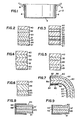
- Fig. 1 is a sectional view of a vessel in the form of a cooking utensil 2 according to this invention.
- the utensil has a bottom wall 4, upstanding side walls 6, and handles 8, and is formed from a single blank of metal which has a plurality of plies roll bonded together using known techniques.
- the utensil may otherwise be formed by drawing, hydroforming, or by other processes known in the art.
- the vessel may take various forms, including the illustrated pot, a skillet, a pan, a griddle or other item.
- plies in a first outer inductively-heatable layer of the utensil have reference numerals starting with the number "2"
- plies in a second, inner layer with a higher thermal conductivity have reference numerals starting with the number "3”.
- the utensil wall shown in Fig. 2 has a first, outer layer formed of a ply 20 of carbon steel clad on its opposite sides with plies 21 and 22 of nonmagnetic stainless steel.
- the carbon steel may be 1005 to 1010 steel, and the stainless steel may be in the 200 or 300 series.
- a principal heat conducting second, inner layer has a copper ply 30 located between two plies 31 and 32 of aluminium. Additionally, there is an interior third layer 40 of stainless steel.
- each ply 21 and 22 has a thickness which is about ten to twenty percent of the total thickness of plies 20, 21 and 22, this total thickness being about 0.38 to 1.27 mm (0.015 to 0.05 inch).
- the plies 30, 31 and 32 have a total thickness of about 0.5 to 2.0 mm (0.02 to 0.08 inch) of which about 0.25 to 0.75 mm (0.01 to 0.03 inch) is formed of the copper core ply 30, and the balance of which is equally occupied by the aluminium cladding plies 31 and 32.
- the interior stainless steel ply 40 has a thickness of about 0.127 to 0.635 mm (0.005 to 0.025 inch).
- the plies 20, 21, 22, 30 and 40 are essentially the same as in Fig. 2; however, the aluminium plies are somewhat different. Rather than having a uniform composition throughout their thickness as in Fig. 2, the aluminium plies in Fig. 3 each have an aluminium alloy core 33 or 34 which is clad on its opposite sides with pure aluminium as shown at 35, 36, 37 and 38.
- a clad aluminum material of this type is commercially available and is sold under the trademark ALCLAD by Aluminum Company of America, Pittsburgh, Pennsylvania.
- the wall structure shown in Fig. 4 is identical to that shown in Fig. 2, except that the stainless steel ply 22 has been omitted.
- the outermost layer is formed of a single ply 23 of a ferromagnetic stainless steel. Materials of this nature are well known, and a preferred form thereof is 430 stainless steel.
- the plies 30, 31, 32 and 40 in Fig. 5 correspond to the similarly referenced plies in Figs. 2 and 4.
- the outer and inner layers of the cooking utensil are identical to the corresponding layers shown in Figs. 2 and 3, the plies of these layers being identified by the reference numerals 20, 21, 22 and 40.
- the second, thermally conductive layer is formed of a single ply 39 of copper which has a thickness of about 0.38 to 1.27 mm (0.015 to 0.050 inch).
- a potential problem in vessels which have one or more plies of carbon steel is that of corrosion at the exposed edges of the metal.
- Known carbon steel vessels are protected from corrosion by coatings of enamel or a stainless steel edge ring.
- Fig. 7 shows an arrangement with which corrosion is detered.
- the wall of the vessel has an outer ply 21 of stainless steel or copper, a ply 20 of carbon steel, a ply 31' of aluminium or copper, and an inner ply 40 of stainless steel.
- the wall can otherwise have a structure as shown in any one of Figs. 2 to 6.
- the upper portion of the vessel wall in Fig. 7 is turned outwardly to form an annular flange 50 with an edge 52 to which all four plies 20, 21, 31' and 40 extend.
- a stainless steel edge ring 54 is located about the edge, the ring 54 having a U-shaped cross section formed by a base 56 which overlies the edge 52 and a pair of flanges 58 and 60 which respectively overlie the interior surface 62 and the exterior surface 64 of the vessel.
- the flange 58 is formed of a single thickness of stainless steel, and the lower flange 60 is bent inwardly upon itself at 66 to form a double thickness of stainless steel.
- a single thickness flange 60 is also possible.
- the ring 54 will be circular to correspond to the circular perimeter of a conventional cooking vessel, and the ring 54 will initially have a radial split which permits its placement in position. After the ring 54 has been placed on the vessel, the ends thereof will be welded together to hold the ring to the vessel in the position shown in Fig. 7.
- the ring 54 encloses the edge of the vessel wall to deter corrosion.
- the ring 54 causes galvanic current between the ply 31' and the carbon steel ply 20 to remain within the confines of the ring 54.
- Aluminium is higher in the galvanic series than carbon steel so, in vessel walls where the aluminium is in contact with the carbon steel, the presence of the ring 54 will cause the aluminium to act as a sacrificial material which deters corrosion of the carbon steel at the edge of the vessel wall.
- Figs. 8 and 9 show other forms of edge rings which can be used to deter corrosion of the carbon steel in the utensil wall.
- the ring 66 has an interior layer 68 of a material which is sacrificial in the galvanic series with respect to the carbon steel.
- the layer 68 may be aluminium, in which event the ring 66 may be formed of commercially available stainless steel clad aluminium.
- the layer 68 may otherwise be zinc or tin, applied to the stainless steel ring 66 by any of the known commercial coating processes for these metals.
- Fig. 9 shows a ring 70 which holds a sacrificial metal 72 in electrical contact with the edge of the vessel wall.
- the metal 72 may be tin, zinc or aluminium, applied by dipping the vessel edge in a bath of the molten sacrificial metal before the stainless steel ring 70 is applied.
- the metal 72 may be applied mechanically by placing a small wire of the metal inside the ring 70, and then flattening the wire when rolling the ring 70 around the perimeter of the vessel.
Landscapes
- Engineering & Computer Science (AREA)
- Food Science & Technology (AREA)
- Physics & Mathematics (AREA)
- Electromagnetism (AREA)
- Cookers (AREA)
- Food-Manufacturing Devices (AREA)
Abstract
An induction heating vessel such as a cooking utensil for use with an induction cooker has a wall formed by a first layer including a magnetic metal (20) which is capable of being inductively heated, and a second layer which includes a ply of aluminium (31, 32) and/or a ply of copper (30), this second layer being in intimate thermally conducting contact with the first layer and being located interiorly of the utensil with respect of the first layer. The first layer may comprise a ply (20) of carbon sheet located between two plies (22) of stainless steel. To deter corrosion of the carbon steel (20) at the edge of the vessel, the circumferential edge of the utensil can be covered by a stainless steel ring (54) which encloses a metal (31') which, in the galvanic series, is sacrificial with respect to the carbon steel (20).
Description
- This invention relates to induction heating vessels, that is vessels which are capable of being inductively heated when placed in an oscillating magnetic field, and particularly such vessels in the form of cooking utensils.
- The principles of induction heating are well known and are described in, for example, US-A-3966426 and US-A-4354082.
- According to this invention there is provided an induction heating vessel, characterised in that the wall thereof is formed of a plurality of layers of metal, each layer being formed of one or more plies of metal, the layers being in intimate thermally-conducting contact with each other, there being a first layer having at least a portion thereof formed of a magnetic material capable of being inductively heated by placement in an oscillating magnetic field, and a second layer located interiorly of the vessel with respect to the first layer, the second layer having a higher thermal conductivity than the first layer and including a ply of copper and/or a ply of aluminium.
- This invention provides vessels which are durable, attractive, possess good thermal conductivity through their thicknesses, and also have good lateral heat transmission in order to avoid or reduce the presence of hot spots in the vessels.
- In vessels having a ply of carbon steel there is a tendency toward corrosion of the carbon steel when exposed at the edge of the vessel.
- Also according to this invention there is provided an induction heating vessel having a wall comprising a ply of carbon steel and having an edge to which the ply of carbon steel extends, characterised by a stainless steel ring covering said edge around the circumference of the vessel, said stainless steel ring enclosing a metal which in the galvanic series is sacrificial with respect to the carbon steel, the sacrificial metal being in electrical contact with the carbon steel ply to deter corrosion at said edge.
- This invention will now be described by way of example with reference to the drawings, in which:-
- Fig. 1 is a sectional side view of a vessel according to the invention;
- Fig. 2 is a sectional view showing the wall of a vessel according to a first embodiment of the invention;
- Fig. 3 is a sectional view showing the wall of a vessel according to a second embodiment of the invention;
- Fig. 4 is a sectional view showing the wall of a vessel according to a third embodiment of the invention;
- Fig. 5 is a sectional view showing the wall of a vessel according to a fourth embodiment of the invention;
- Fig. 6 is a sectional view showing the wall of a vessel according to a fifth embodiment of the invention;
- Fig. 7 is a sectional view showing the edge of 4 vessel according to the invention, and provided with a ring which deters corrosion at the edge of the vessel; and
- Figs. 8 and 9 are sectional views showing two arrangements whereby corrosion of carbon steel at the edge of a vessel can be deterred by locating a sacrificial metal between a perimetral ring and the edge of the vessel.
- Fig. 1 is a sectional view of a vessel in the form of a
cooking utensil 2 according to this invention. The utensil has a bottom wall 4,upstanding side walls 6, and handles 8, and is formed from a single blank of metal which has a plurality of plies roll bonded together using known techniques. The utensil may otherwise be formed by drawing, hydroforming, or by other processes known in the art. The vessel may take various forms, including the illustrated pot, a skillet, a pan, a griddle or other item. - For convenience of identification plies in a first outer inductively-heatable layer of the utensil have reference numerals starting with the number "2", and plies in a second, inner layer with a higher thermal conductivity have reference numerals starting with the number "3".
- The utensil wall shown in Fig. 2 has a first, outer layer formed of a
ply 20 of carbon steel clad on its opposite sides withplies copper ply 30 located between twoplies third layer 40 of stainless steel. - With respect to the thickness of the plies in Fig. 2, each
ply plies plies copper core ply 30, and the balance of which is equally occupied by thealuminium cladding plies stainless steel ply 40 has a thickness of about 0.127 to 0.635 mm (0.005 to 0.025 inch). - In Fig. 3, the
plies aluminium alloy core - The wall structure shown in Fig. 4 is identical to that shown in Fig. 2, except that the
stainless steel ply 22 has been omitted. - Referring to Fig. 5, the outermost layer is formed of a
single ply 23 of a ferromagnetic stainless steel. Materials of this nature are well known, and a preferred form thereof is 430 stainless steel. Theplies - In the embodiment of Fig. 6, the outer and inner layers of the cooking utensil are identical to the corresponding layers shown in Figs. 2 and 3, the plies of these layers being identified by the
reference numerals single ply 39 of copper which has a thickness of about 0.38 to 1.27 mm (0.015 to 0.050 inch). - A potential problem in vessels which have one or more plies of carbon steel is that of corrosion at the exposed edges of the metal. Known carbon steel vessels are protected from corrosion by coatings of enamel or a stainless steel edge ring.
- Fig. 7 shows an arrangement with which corrosion is detered. The wall of the vessel has an
outer ply 21 of stainless steel or copper, aply 20 of carbon steel, a ply 31' of aluminium or copper, and aninner ply 40 of stainless steel. The wall can otherwise have a structure as shown in any one of Figs. 2 to 6. - The upper portion of the vessel wall in Fig. 7 is turned outwardly to form an
annular flange 50 with anedge 52 to which all fourplies steel edge ring 54 is located about the edge, thering 54 having a U-shaped cross section formed by abase 56 which overlies theedge 52 and a pair offlanges interior surface 62 and the exterior surface 64 of the vessel. Theflange 58 is formed of a single thickness of stainless steel, and thelower flange 60 is bent inwardly upon itself at 66 to form a double thickness of stainless steel. Asingle thickness flange 60 is also possible. In most instances, thering 54 will be circular to correspond to the circular perimeter of a conventional cooking vessel, and thering 54 will initially have a radial split which permits its placement in position. After thering 54 has been placed on the vessel, the ends thereof will be welded together to hold the ring to the vessel in the position shown in Fig. 7. - The
ring 54 encloses the edge of the vessel wall to deter corrosion. When the ply 31' is aluminium, thering 54 causes galvanic current between the ply 31' and thecarbon steel ply 20 to remain within the confines of thering 54. Aluminium is higher in the galvanic series than carbon steel so, in vessel walls where the aluminium is in contact with the carbon steel, the presence of thering 54 will cause the aluminium to act as a sacrificial material which deters corrosion of the carbon steel at the edge of the vessel wall. - Figs. 8 and 9 show other forms of edge rings which can be used to deter corrosion of the carbon steel in the utensil wall.
- In Fig. 8, the
ring 66 has aninterior layer 68 of a material which is sacrificial in the galvanic series with respect to the carbon steel. Thelayer 68 may be aluminium, in which event thering 66 may be formed of commercially available stainless steel clad aluminium. Thelayer 68 may otherwise be zinc or tin, applied to thestainless steel ring 66 by any of the known commercial coating processes for these metals. - Fig. 9 shows a
ring 70 which holds asacrificial metal 72 in electrical contact with the edge of the vessel wall. Themetal 72 may be tin, zinc or aluminium, applied by dipping the vessel edge in a bath of the molten sacrificial metal before thestainless steel ring 70 is applied. Alternatively, themetal 72 may be applied mechanically by placing a small wire of the metal inside thering 70, and then flattening the wire when rolling thering 70 around the perimeter of the vessel.
Claims (14)
1. An induction heating vessel (2), characterised in that the wall (6) thereof is formed of a plurality of layers of metal, each layer being formed of one or more plies of metal, the layers being in intimate thermally-conducting contact with each other, there being a first layer having at least a portion (20) thereof formed of a magnetic material capable of being inductively heated by placement in an oscillating magnetic field, and a second layer located interiorly of the vessel (2) with respect to the first layer, the second layer having a higher thermal conductivity than the first layer and including a ply (30, 39) of copper and/or for a ply (31, 32) of aluminium.
2. A vessel as claimed in Claim 1, characterised in that the second layer comprises two plies (31 and 32) of aluminium and one ply (30) of copper located between the two plies (31 and 32) of aluminium.
3. A vessel as claimed in Claim 1 or Claim 2, characterised in that the or each ply (31, 32) of aluminium has a core (33, 34) of aluminium alloy which is clad on its opposite surfaces with pure aluminium (35, 36, 37, 38).
4. A vessel as claimed in any preceding claim, characterised by a third layer (40) of stainless steel located interiorly of the vessel (2) with respect to the second layer.
5. A vessel as claimed in any preceding claim, characterised in that the first layer is formed of a single ply (23) magnetic stainless steel,
6. A vessel as claimed in Claim 5, characterised in that the first layer has a ply (21) of nonmagnetic stainless steel located exteriorly of the vessel (2) with respect to the ply (20) of magnetic stainless steel.
7. A vessel as claimed in Claim 7, characterised in that the first layer has a second ply (22) of nonmagnetic stainless steel, the ply of magnetic stainless steel being located between the two plies (21, 22) of nonmagnetic stainless steel.
8. A vessel as claimed in any one of Claims 5 to 7, characterised in that the ply (23) of magnetic stainless steel is of carbon steel.
9. A vessel as claimed in any preceding claim, in which the wall (6) has an edge (52) extending around the circumference of the vessel (2), characterised by a stainless steel ring (54, 66, 70) covering said edge (52).
10. A vessel as claimed in Claim 9 when dependent upon Claim 8, characterised in that the stainless steel ring (54, 66, 70) has a U-shaped cross section with a base (56) which overlies said edge (52) and a pair of flanges (58, 60) which overlie the interior and exterior surfaces of the wall (6) of the vessel (2) adjacent to said edge (52), the stainless ring (54, 66, 70) enclosing a metal (31, 68, 72) which in the galvanic series is sacrificial with respect to the carbon steel, the sacrificial metal (31, 68, 72) being in electrical contact with the carbon steel ply (20) to deter corrosion at said edge (52).
11. An induction heating vessel having a wall comprising a ply (20) of carbon steel and having an edge (52) to which the ply (20) of carbon steel extends, characterised by a stainless steel ring (54, 66, 70) covering said edge (52) around the circumference of the vessel, said stainless steel ring (54, 66, 70) enclosing a metal (31, 68, 72) which in the galvanic series is sacrificial with respect to the carbon steel (20), the sacrificial metal (31, 68, 72) being in electrical contact with the carbon steel ply (20) to deter corrosion at said edge (52).
12. A vessel as claimed in Claim 11, characterised in that the sacrificial metal is a ply (31) of aluminum in the wall of the vessel.
13. A vessel as claimed in Claim 11, characterised in that the sacrificial metal (68, 72) is located between the stainless steel ring (66, 70) and the edge (52) of the wall of the vessel.
14. A vessel as claimed in any one of Claims 11 to 13, characterised in that the stainless steel ring (54, 66, 70) has a U-shaped cross section with a base (56) which overlies said edge (52) and a pair of flanges (58, 61) which overlie interior and exterior surfaces of the wall of the vessel adjacent to said edge (52).
Applications Claiming Priority (2)
| Application Number | Priority Date | Filing Date | Title |
|---|---|---|---|
| US692731 | 1985-01-18 | ||
| US06/692,731 US4646935A (en) | 1985-01-18 | 1985-01-18 | Induction cooking utensils |
Publications (1)
| Publication Number | Publication Date |
|---|---|
| EP0192333A1 true EP0192333A1 (en) | 1986-08-27 |
Family
ID=24781778
Family Applications (1)
| Application Number | Title | Priority Date | Filing Date |
|---|---|---|---|
| EP86300329A Withdrawn EP0192333A1 (en) | 1985-01-18 | 1986-01-17 | Induction heating vessels |
Country Status (5)
| Country | Link |
|---|---|
| US (1) | US4646935A (en) |
| EP (1) | EP0192333A1 (en) |
| JP (1) | JPS61170415A (en) |
| AU (1) | AU5245286A (en) |
| NO (1) | NO860155L (en) |
Cited By (3)
| Publication number | Priority date | Publication date | Assignee | Title |
|---|---|---|---|---|
| EP0228774A1 (en) * | 1985-10-11 | 1987-07-15 | Ema Corp. | Composite material for induction heating |
| WO2007042247A1 (en) * | 2005-10-10 | 2007-04-19 | Eisfink Max Maier Gmbh & Co. Kg | Gn container |
| US10300678B2 (en) * | 2012-12-11 | 2019-05-28 | Thyssenkrupp Steel Europe Ag | Surface-coated steel sheet and process for the production thereof |
Families Citing this family (66)
| Publication number | Priority date | Publication date | Assignee | Title |
|---|---|---|---|---|
| WO1989001752A1 (en) * | 1987-08-24 | 1989-03-09 | Fissler Gmbh | Cooking utensil |
| US5134265A (en) * | 1990-02-16 | 1992-07-28 | Metcal, Inc. | Rapid heating, uniform, highly efficient griddle |
| US5227597A (en) * | 1990-02-16 | 1993-07-13 | Electric Power Research Institute | Rapid heating, uniform, highly efficient griddle |
| US5844212A (en) * | 1991-10-23 | 1998-12-01 | Gas Research Institute | Dual surface heaters |
| JPH06282229A (en) * | 1993-01-27 | 1994-10-07 | Unitika Ltd | Anti-theft label |
| US6097014A (en) * | 1994-02-02 | 2000-08-01 | Florinius-Investimentos E Servicos Internacionais Lda | Apparatus and process for delivery of prepared foods |
| DE59407882D1 (en) * | 1994-03-18 | 1999-04-08 | Clad Lizenz Ag | Multi-layer, cold-formable and deep-drawable composite body made of metal |
| DE59500494D1 (en) * | 1994-04-15 | 1997-09-18 | Fissler Gmbh | Cooking and / or cooking device, which is set up for a bottom-side supply of thermal energy by heat conduction or by electromagnetic induction |
| US5770837A (en) * | 1994-11-18 | 1998-06-23 | Sumitomo Electric Industries, Ltd. | Metal plate for electromagnetic heating |
| US5954984A (en) * | 1996-07-31 | 1999-09-21 | Thermal Solutions Inc. | Heat retentive food servingware with temperature self-regulating phase change core |
| US6232585B1 (en) | 1998-05-19 | 2001-05-15 | Thermal Solutions, Inc. | Temperature self-regulating food delivery system |
| US6109504A (en) * | 1998-07-10 | 2000-08-29 | Clad Metals Llc | Copper core cooking griddle and method of making same |
| IT1309067B1 (en) | 1999-01-22 | 2002-01-16 | Marino Scaburri | INDUCTION HEATING SYSTEM OF BODIES IN GENERAL, IN SPECIAL FOR FOOD COOKING |
| US6433313B1 (en) | 2000-02-15 | 2002-08-13 | Vesture Corporation | Apparatus and method for heated food delivery |
| US6384387B1 (en) | 2000-02-15 | 2002-05-07 | Vesture Corporation | Apparatus and method for heated food delivery |
| US6780527B2 (en) * | 2000-06-27 | 2004-08-24 | Citizen Watch Co., Ltd. | Decorative article having white film and production method therefor |
| ATE306840T1 (en) * | 2001-11-30 | 2005-11-15 | Imphy Alloys | COOKING VESSEL WITH A BASE MADE OF MULTI-LAYER MATERIAL AND A SIDE WALL, AND ARTICLE MADE OF MULTI-LAYER MATERIAL |
| FR2833019B1 (en) * | 2001-11-30 | 2004-09-10 | Imphy Ugine Precision | FERROMAGNETIC ALLOY FOR INDUCTION COOKING |
| US6926971B2 (en) * | 2002-06-28 | 2005-08-09 | All-Clad Metalcrafters Llc | Bonded metal components having uniform thermal conductivity characteristics and method of making same |
| US7906221B2 (en) * | 2002-06-28 | 2011-03-15 | All-Clad Metalcrafters Llc | Bonded metal components having uniform thermal conductivity characteristics |
| US20040229079A1 (en) * | 2002-06-28 | 2004-11-18 | Groll William A. | Composite cookware having decorative outer surface and improved induction heating characteristics |
| US20040137260A1 (en) * | 2002-11-19 | 2004-07-15 | Clad Metals Llc | Copper clad aluminum core composite material suitable for making a cellular telephone transmission tower antenna |
| US6953919B2 (en) * | 2003-01-30 | 2005-10-11 | Thermal Solutions, Inc. | RFID-controlled smart range and method of cooking and heating |
| WO2004082445A2 (en) * | 2003-03-19 | 2004-09-30 | Clad Metals Llc | Composite cookware having ceramic coated aluminum edges |
| US6802432B1 (en) * | 2003-06-17 | 2004-10-12 | First Enamel Industrial Corp. | Enamel cooking ware |
| US20050145618A1 (en) * | 2003-08-04 | 2005-07-07 | Eckert C. E. | Electric heater assembly |
| US20050189346A1 (en) * | 2003-08-04 | 2005-09-01 | Eckert C. E. | Electric heater assembly |
| AU2003262651A1 (en) * | 2003-08-13 | 2005-03-10 | Clad Metals Llc | Bonded metal components having uniform thermal conductivity characteristics and method of making same |
| US20050040171A1 (en) * | 2003-08-20 | 2005-02-24 | P.T. Maspion | Multi clad cookware |
| US7353981B2 (en) * | 2004-01-15 | 2008-04-08 | All-Clad Metalcrafters Llc | Method of making a composite metal sheet |
| US7097064B2 (en) * | 2004-01-28 | 2006-08-29 | Meyer Intellectual Properties Limited | Double wall cooking vessel |
| US7488515B2 (en) * | 2004-03-19 | 2009-02-10 | All-Clad Metalcrafters Llc | Method of making non-stick cookware |
| KR100553316B1 (en) * | 2004-04-16 | 2006-02-20 | 한국과학기술연구원 | Structure of Steel/Al Clad for Cooking Jar |
| US7573005B2 (en) * | 2004-04-22 | 2009-08-11 | Thermal Solutions, Inc. | Boil detection method and computer program |
| ATE389349T1 (en) * | 2004-12-31 | 2008-04-15 | Eisfink Max Maier Gmbh & Co Kg | CONTAINERS, ESPECIALLY GASTRONORM (GN) CONTAINERS |
| JP2006247065A (en) * | 2005-03-09 | 2006-09-21 | Sumitomo Electric Fine Polymer Inc | Composite material and manufacturing method |
| US7147634B2 (en) | 2005-05-12 | 2006-12-12 | Orion Industries, Ltd. | Electrosurgical electrode and method of manufacturing same |
| US8814861B2 (en) | 2005-05-12 | 2014-08-26 | Innovatech, Llc | Electrosurgical electrode and method of manufacturing same |
| US20070000915A1 (en) * | 2005-06-21 | 2007-01-04 | Meyer Intellectual Properties Limited | Laminated Cookware with a Protected Edge |
| US8569665B2 (en) * | 2006-10-17 | 2013-10-29 | Meyer Intellectual Properties Limited | Cookware with tarnish protected copper exterior |
| US7913372B2 (en) * | 2006-12-21 | 2011-03-29 | Meyer Intellectual Properties Limited | Insulated cooking vessel |
| US7960034B2 (en) * | 2007-03-30 | 2011-06-14 | All-Clad Metalcrafters Llc | Multi-ply cookware with copper-aluminum-stainless steel |
| US20090065497A1 (en) * | 2007-09-07 | 2009-03-12 | Bose Corporation | Induction cookware |
| US8796598B2 (en) * | 2007-09-07 | 2014-08-05 | Bose Corporation | Induction cookware |
| US7989012B2 (en) * | 2007-09-26 | 2011-08-02 | Kellogg Company | Induction cooking structure and system and method of using the same |
| US8065999B2 (en) * | 2008-07-14 | 2011-11-29 | W.C. Bradley Co. | Adjustable cooking grate for barbeque grills |
| US20100147832A1 (en) * | 2008-12-16 | 2010-06-17 | Barker Iii Charles R | Induction cookware identifying |
| DE212010000137U1 (en) * | 2009-09-04 | 2012-04-30 | Meyer Intellectual Properties Limited | Anodised, coated copper cookware |
| EP2371248B1 (en) | 2010-03-31 | 2012-12-12 | Castey Dominguez, Ramon | Kitchen utensil adapted for induction cooking |
| CH703032A2 (en) * | 2010-04-25 | 2011-10-31 | Johan Laubscher | Cookware with a deformation-free soil and process for its production. |
| TWM400281U (en) * | 2010-09-01 | 2011-03-21 | Pro Iroda Ind Inc | Cookware with five layered composite metal material |
| TWI466650B (en) * | 2010-11-08 | 2015-01-01 | Ind Tech Res Inst | Cooking utensil and manufacturing method thereof |
| US8602248B2 (en) | 2011-03-02 | 2013-12-10 | Bose Corporation | Cooking utensil |
| US9585202B2 (en) * | 2011-05-20 | 2017-02-28 | Cooktek Induction Systems, Llc | Induction-based food holding/warming system and method |
| US9060639B2 (en) | 2011-07-13 | 2015-06-23 | All-Clad Metalcrafters Llc | Multi-ply aluminum bonded cookware |
| US8984750B2 (en) * | 2012-02-24 | 2015-03-24 | Federal-Mogul Corporation | Static gasket with wire compression limiter |
| US10081163B2 (en) | 2013-03-15 | 2018-09-25 | All-Clad Metalcrafters Llc | Cooking utensil having a graphite core |
| CN107960848B (en) * | 2013-03-15 | 2020-02-04 | 全包层金属制品公司 | Method for manufacturing selectively bonded composite for cookware manufacture |
| CN104510324A (en) * | 2013-09-29 | 2015-04-15 | 李灿荣 | Inclined surface heating type anti-sticking food cooking appliance |
| CA2958334C (en) * | 2014-08-18 | 2019-06-04 | Garland Commercial Industries Llc | Graphite composite cooking plate |
| DE102014015961A1 (en) * | 2014-10-31 | 2016-05-04 | Sig Technology Ag | Container precursor, in particular for producing a food container, from a laminate with peeled and partially turned on itself edge region |
| US10472157B1 (en) | 2015-08-14 | 2019-11-12 | CLAW Biotech Holdings LLC | Pathogen eliminating article |
| US9675079B1 (en) | 2016-06-16 | 2017-06-13 | CLAW Biotech Holdings LLC | Pathogen eliminating article |
| KR20190041996A (en) * | 2016-06-24 | 2019-04-23 | 엔지니어드 머티리얼즈 솔루션즈, 엘엘씨 | Nickel-Free Metal Cookware with Excellent Corrosion Characteristics and Manufacturing Method Thereof |
| US10356853B2 (en) | 2016-08-29 | 2019-07-16 | Cooktek Induction Systems, Llc | Infrared temperature sensing in induction cooking systems |
| US10959426B1 (en) | 2016-11-28 | 2021-03-30 | CLAW Biotech Holdings LLC | Pathogen eliminating article and methods of manufacturing and using the same |
Citations (9)
| Publication number | Priority date | Publication date | Assignee | Title |
|---|---|---|---|---|
| FR67132E (en) * | 1954-02-12 | 1957-11-22 | Wmf Wuerttemberg Metallwaren | Improvements made to metal containers, more specifically to utensils for boiling, frying or cooking food, with stainless rim |
| US2941289A (en) * | 1954-04-21 | 1960-06-21 | Thomas B Chace | Method of making clad metal cooking utensils |
| DE1083999B (en) * | 1954-07-21 | 1960-06-23 | Wmf Wuerttemberg Metallwaren | Process for the production of an enamelled metal vessel for cooking, roasting or baking with a rustproof rim |
| FR2075574A5 (en) * | 1970-01-15 | 1971-10-08 | Racz Nick | |
| DE2657699A1 (en) * | 1976-12-20 | 1978-06-22 | Bosch Siemens Hausgeraete | Cooking utensil for inductive cooking - has base pref. of metal with coating possessing low permeability |
| FR2437184A1 (en) * | 1978-09-29 | 1980-04-25 | Ardal Og Sunndal Verk | KITCHEN UTENSILS SUCH AS COMPOSITE SAUCEPANS AND MANUFACTURING METHOD THEREOF |
| FR2453627A1 (en) * | 1979-04-10 | 1980-11-07 | Equipinox Equip Acier Inoxydab | Cooking utensil with composite base - has lowest part of base made of ferromagnetic material to suit cookers using plates heated by induction |
| EP0036978A1 (en) * | 1980-04-01 | 1981-10-07 | Württembergische Metallwarenfabrik Ag. | Process for manufacturing enamelled kitchen utensils |
| EP0111867A1 (en) * | 1982-12-14 | 1984-06-27 | Hackman Housewares Oy Ab | Cooking vessel of stainless steel for all types of heat sources |
Family Cites Families (8)
| Publication number | Priority date | Publication date | Assignee | Title |
|---|---|---|---|---|
| US3445630A (en) * | 1967-05-15 | 1969-05-20 | Composite Metal Products Inc | Composite cooking vessels |
| US3930806A (en) * | 1970-01-15 | 1976-01-06 | Burdett Manufacturing Company | Laminated cookware units |
| US3909591A (en) * | 1972-03-16 | 1975-09-30 | John B Ulam | Cooking vessel |
| US3919763A (en) * | 1972-03-16 | 1975-11-18 | John B Ulam | Method of making a cooking vessel |
| US3966426A (en) * | 1972-03-24 | 1976-06-29 | White-Westinghouse Corporation | Cooking vessel for use with induction heating cooking unit |
| US3941569A (en) * | 1972-11-10 | 1976-03-02 | Toyo Kogyo Co., Ltd. | Method for making ferrous metal having improved resistances to corrosion at elevated temperatures and to oxidization |
| DE2906912A1 (en) * | 1979-02-22 | 1980-09-04 | Sachs Systemtechnik Gmbh | COOKING VESSEL FOR AN INDUCTION COOKER |
| US4246045A (en) * | 1979-04-24 | 1981-01-20 | Clad Metals, Inc. | Multiple member clad metal products and methods of making the same |
-
1985
- 1985-01-18 US US06/692,731 patent/US4646935A/en not_active Expired - Lifetime
- 1985-07-10 JP JP60152155A patent/JPS61170415A/en active Granted
-
1986
- 1986-01-17 AU AU52452/86A patent/AU5245286A/en not_active Abandoned
- 1986-01-17 EP EP86300329A patent/EP0192333A1/en not_active Withdrawn
- 1986-01-17 NO NO860155A patent/NO860155L/en unknown
Patent Citations (9)
| Publication number | Priority date | Publication date | Assignee | Title |
|---|---|---|---|---|
| FR67132E (en) * | 1954-02-12 | 1957-11-22 | Wmf Wuerttemberg Metallwaren | Improvements made to metal containers, more specifically to utensils for boiling, frying or cooking food, with stainless rim |
| US2941289A (en) * | 1954-04-21 | 1960-06-21 | Thomas B Chace | Method of making clad metal cooking utensils |
| DE1083999B (en) * | 1954-07-21 | 1960-06-23 | Wmf Wuerttemberg Metallwaren | Process for the production of an enamelled metal vessel for cooking, roasting or baking with a rustproof rim |
| FR2075574A5 (en) * | 1970-01-15 | 1971-10-08 | Racz Nick | |
| DE2657699A1 (en) * | 1976-12-20 | 1978-06-22 | Bosch Siemens Hausgeraete | Cooking utensil for inductive cooking - has base pref. of metal with coating possessing low permeability |
| FR2437184A1 (en) * | 1978-09-29 | 1980-04-25 | Ardal Og Sunndal Verk | KITCHEN UTENSILS SUCH AS COMPOSITE SAUCEPANS AND MANUFACTURING METHOD THEREOF |
| FR2453627A1 (en) * | 1979-04-10 | 1980-11-07 | Equipinox Equip Acier Inoxydab | Cooking utensil with composite base - has lowest part of base made of ferromagnetic material to suit cookers using plates heated by induction |
| EP0036978A1 (en) * | 1980-04-01 | 1981-10-07 | Württembergische Metallwarenfabrik Ag. | Process for manufacturing enamelled kitchen utensils |
| EP0111867A1 (en) * | 1982-12-14 | 1984-06-27 | Hackman Housewares Oy Ab | Cooking vessel of stainless steel for all types of heat sources |
Cited By (3)
| Publication number | Priority date | Publication date | Assignee | Title |
|---|---|---|---|---|
| EP0228774A1 (en) * | 1985-10-11 | 1987-07-15 | Ema Corp. | Composite material for induction heating |
| WO2007042247A1 (en) * | 2005-10-10 | 2007-04-19 | Eisfink Max Maier Gmbh & Co. Kg | Gn container |
| US10300678B2 (en) * | 2012-12-11 | 2019-05-28 | Thyssenkrupp Steel Europe Ag | Surface-coated steel sheet and process for the production thereof |
Also Published As
| Publication number | Publication date |
|---|---|
| AU5245286A (en) | 1986-07-24 |
| NO860155L (en) | 1986-07-21 |
| JPS61170415A (en) | 1986-08-01 |
| US4646935A (en) | 1987-03-03 |
| JPH0115290B2 (en) | 1989-03-16 |
Similar Documents
| Publication | Publication Date | Title |
|---|---|---|
| EP0192333A1 (en) | Induction heating vessels | |
| EP0111867B1 (en) | Cooking vessel of stainless steel for all types of heat sources | |
| JPS6127108Y2 (en) | ||
| US4350259A (en) | Stainless steel container with thermoradiating bottom | |
| EP0221848A1 (en) | Cooking vessel | |
| US3966426A (en) | Cooking vessel for use with induction heating cooking unit | |
| US3934748A (en) | Cookware containers | |
| US5487329A (en) | Cooking or boiling pot | |
| JPH0847450A (en) | Cooking instrument wherein heat energy is provided to bottom wall by heat conduction or electromagnetic induction | |
| US3909591A (en) | Cooking vessel | |
| KR20000047838A (en) | Cooking vessel for induction heating and alloy for producing such a vessel | |
| US5809630A (en) | Method of manufacturing a culinary vessel with reinforced bottom | |
| GB2034173A (en) | Cooking utensils | |
| CN111031864A (en) | Multi-layer cooking support capable of being inductively heated | |
| CA1299381C (en) | Microwaveable/stovetop cooking utensil | |
| ITMI930249A1 (en) | PROCEDURE FOR THE CREATION OF A STAINLESS STEEL COOKING POT WITH DECORATED BOTTOM, AND ITS CONTAINER | |
| US5881635A (en) | Enamelled cookware and method of manufacturing it | |
| JPS5911436Y2 (en) | Non-metallic container for induction cooker | |
| JPS6337752Y2 (en) | ||
| JP2558429B2 (en) | Container for electromagnetic cooker | |
| JP3287549B2 (en) | Electromagnetic induction heating cooking container | |
| GB2121674A (en) | Stainless steel cookware | |
| JPH0453508A (en) | Heat cooking utensil | |
| US3363307A (en) | Method of making electrically heated cooking vessels | |
| EP0475427B1 (en) | A heating element and a method for manufacturing the same |
Legal Events
| Date | Code | Title | Description |
|---|---|---|---|
| PUAI | Public reference made under article 153(3) epc to a published international application that has entered the european phase |
Free format text: ORIGINAL CODE: 0009012 |
|
| AK | Designated contracting states |
Kind code of ref document: A1 Designated state(s): BE CH DE FR GB IT LI SE |
|
| 17P | Request for examination filed |
Effective date: 19870226 |
|
| 17Q | First examination report despatched |
Effective date: 19881221 |
|
| STAA | Information on the status of an ep patent application or granted ep patent |
Free format text: STATUS: THE APPLICATION IS DEEMED TO BE WITHDRAWN |
|
| 18D | Application deemed to be withdrawn |
Effective date: 19890503 |
|
| RIN1 | Information on inventor provided before grant (corrected) |
Inventor name: ULAM, JOHN BERNARD |