EP0192238B1 - Thermomechanical analysis apparatus - Google Patents
Thermomechanical analysis apparatus Download PDFInfo
- Publication number
- EP0192238B1 EP0192238B1 EP86102068A EP86102068A EP0192238B1 EP 0192238 B1 EP0192238 B1 EP 0192238B1 EP 86102068 A EP86102068 A EP 86102068A EP 86102068 A EP86102068 A EP 86102068A EP 0192238 B1 EP0192238 B1 EP 0192238B1
- Authority
- EP
- European Patent Office
- Prior art keywords
- probe
- coil
- magnet assembly
- error signal
- sample
- Prior art date
- Legal status (The legal status is an assumption and is not a legal conclusion. Google has not performed a legal analysis and makes no representation as to the accuracy of the status listed.)
- Expired
Links
- 230000000930 thermomechanical effect Effects 0.000 title claims description 5
- 239000000523 sample Substances 0.000 claims description 64
- 230000004044 response Effects 0.000 claims description 8
- 230000000694 effects Effects 0.000 claims description 4
- 238000012544 monitoring process Methods 0.000 claims description 2
- 230000008602 contraction Effects 0.000 claims 1
- 230000001939 inductive effect Effects 0.000 claims 1
- XEEYBQQBJWHFJM-UHFFFAOYSA-N Iron Chemical compound [Fe] XEEYBQQBJWHFJM-UHFFFAOYSA-N 0.000 description 4
- 229910052782 aluminium Inorganic materials 0.000 description 3
- XAGFODPZIPBFFR-UHFFFAOYSA-N aluminium Chemical compound [Al] XAGFODPZIPBFFR-UHFFFAOYSA-N 0.000 description 3
- 239000012530 fluid Substances 0.000 description 3
- 230000006870 function Effects 0.000 description 3
- 238000005259 measurement Methods 0.000 description 3
- 239000010453 quartz Substances 0.000 description 3
- VYPSYNLAJGMNEJ-UHFFFAOYSA-N silicon dioxide Inorganic materials O=[Si]=O VYPSYNLAJGMNEJ-UHFFFAOYSA-N 0.000 description 3
- 238000012546 transfer Methods 0.000 description 3
- IJGRMHOSHXDMSA-UHFFFAOYSA-N Atomic nitrogen Chemical compound N#N IJGRMHOSHXDMSA-UHFFFAOYSA-N 0.000 description 2
- 239000004809 Teflon Substances 0.000 description 2
- 229920006362 Teflon® Polymers 0.000 description 2
- 238000006073 displacement reaction Methods 0.000 description 2
- 229910052742 iron Inorganic materials 0.000 description 2
- 239000004593 Epoxy Substances 0.000 description 1
- 239000000919 ceramic Substances 0.000 description 1
- 238000010276 construction Methods 0.000 description 1
- 238000012937 correction Methods 0.000 description 1
- 238000013016 damping Methods 0.000 description 1
- 230000001419 dependent effect Effects 0.000 description 1
- 238000010586 diagram Methods 0.000 description 1
- 239000007789 gas Substances 0.000 description 1
- 238000010438 heat treatment Methods 0.000 description 1
- 230000010354 integration Effects 0.000 description 1
- 238000005339 levitation Methods 0.000 description 1
- 239000007788 liquid Substances 0.000 description 1
- 229910052751 metal Inorganic materials 0.000 description 1
- 239000002184 metal Substances 0.000 description 1
- 229910052757 nitrogen Inorganic materials 0.000 description 1
- 230000006903 response to temperature Effects 0.000 description 1
- 230000000717 retained effect Effects 0.000 description 1
- 230000002000 scavenging effect Effects 0.000 description 1
- 238000012360 testing method Methods 0.000 description 1
Images


Classifications
-
- G—PHYSICS
- G01—MEASURING; TESTING
- G01N—INVESTIGATING OR ANALYSING MATERIALS BY DETERMINING THEIR CHEMICAL OR PHYSICAL PROPERTIES
- G01N25/00—Investigating or analyzing materials by the use of thermal means
- G01N25/16—Investigating or analyzing materials by the use of thermal means by investigating thermal coefficient of expansion
-
- G—PHYSICS
- G01—MEASURING; TESTING
- G01N—INVESTIGATING OR ANALYSING MATERIALS BY DETERMINING THEIR CHEMICAL OR PHYSICAL PROPERTIES
- G01N25/00—Investigating or analyzing materials by the use of thermal means
Definitions
- This invention relates to an instrument designed to measure physical responses in samples undergoing temperature changes according to the preamble of claim 1.
- An instrument of this kind is known, for example, from US-A-4 354 764.
- thermomechanical analysis apparatus in United States Patent 3,589,167, which issued June 29, 1971 to the assignee of the present invention, there is disclosed a thermomechanical analysis apparatus. That apparatus includes a probe assembly which is suspended in substantially weightless contact with a sample material over a range of displacement of the probe. This substantially weightless contact is achieved by means of a fluid reservoir and a float which is submerged in the fluid and coupled to the probe. Weights are added manually to the probe assembly to just offset the buoyancy of the float. As the height of a sample under test changes, the substantially weightless probe moves up or down in response.
- LVDT linear variable differential transformer
- the magnetic core of the LVDT is mounted on a non-magnetic rod which supports the probe.
- a rack and pinion are provided for moving the LVDT coil assembly to achieve a null prior to beginning a measurement.
- the rod member which supports the probe passes through a pair of roller bearings.
- the entire assembly is suspended from a frame at a pair of spaced support points.
- the thermomechanical analysis apparatus of the present invention includes a support for positioning a sample in a programmable temperature environment, a vertical displaceable probe positionable in contact with the sample surface, means for substantially offsetting the effect of the weight of the probe on the sample, and means for monitoring movement of the probe in response to changing physical characteristics of the sample, wherein the weight offsetting means is a linear motor.
- This linear motor comprises a substantially cylindrical magnet assembly.
- the linear motor also includes a linearly, vertically, movable armature coaxial with the magnet assembly and including a coil energizable to generate a magnetic field operable with the field of said magnet assembly to exert a vertical axial force on the armature. Further, means are provided for controllably energizing the coil with an electrical current.
- the invention is directed to the improvement wherein the weight offsetting means supports the probe and the substantially cylindrical magnet assembly is mounted above and is coaxial with the probe.
- FIG. 2 there is illustrated an apparatus in accordance with the invention comprising a stand 10 upon which is positioned a furnace and heat exchanger assembly 12.
- This assembly is similar to that of the above-referenced prior art patent and includes an electrically heated furnace 14.
- the assembly may be cooled by liquid nitrogen and the furnace may be heated.
- the assembly 12 may be programmed through a range of temperatures from -180°C to 1000°C.
- a housing 16 Suspended above the furnace-heat exchanger assembly 12 is a housing 16 from which depends a quartz furnace tube 18.
- the assembly 12 may be raised into a position as illustrated by the dashed lines where it will receive the furnace tube 18.
- the bracket 20 includes a central opening 22 upon which is positioned a mounting ring 24 by means of screws (not shown). Extending downwardly from the mounting ring 24 through the opening 22 is a cylinder 26 which has a number of cut-outs 28 in its side wall and carries three outwardly radially spaced mounting lugs 30 on its lower end.
- the upper surface of mounting ring 24 has a circular ring-shaped tapered seat 32.
- the surface of the seat 32 is ideally a portion of the surface of a sphere. For practical purposes it may be conical.
- Seated upon the seat 32 is the outer lower edge of a bearing ring 34 of rectangular cross-section. Bearing ring 34 is mounted to the bottom of a cylindrical magnet assembly 36.
- Four adjusting screws 38 are threaded into mounting ring 24 with their tapered heads bearing against the upper edge of the bearing ring 34.
- a cylindrical aluminum housing 42 Suspended from the lugs 30 by means of screws 40 is a cylindrical aluminum housing 42.
- the housing 42 includes a central opening 44 within which is mounted a conventional linear variable differential transformer (LVDT) 46.
- the housing 42 also includes a pair of diametrically positioned parallel wells which contain cartridge heaters 48. Temperature control is maintained by a sensor 50 mounted in the side of the housing 42.
- LVDT linear variable differential transformer
- chamber 52 Suspended from the bottom of the housing 42 is a chamber 52.
- chamber 52 includes an upper wall 54 which is substantially cylindrical for something more than 180° but is formed to provide a pair of spaced parallel vertical side walls 56.
- a latch 58 which is in the form of a cylinder having a cut-out 60.
- Latch 58 is retained at one end by an enlarged head 62 and at the other by an L-shaped actuating level 64.
- Protruding inwardly from the cylindrical wall 54 is a boss 66 which defines a port 68 communicating with the end of a scavenging gas delivery tube 70.
- chuck 72 Depending from chamber 52 is a chuck 72 comprising an externally threaded male stud 74 and an internally threaded female clamp 76. These members cooperate in the usual manner to secure the tapered upper end of quartz furnace tube 18.
- This tube is similar to that disclosed in the above-referenced prior art patent and includes at its lower end a pair of aligned openings 80 and a sample support surface 82.
- the magnet assembly 36 comprises one element of a linear motor. It comprises an iron outer cylinder 84 and a coaxial iron inner cylinder 86 which are joined at their upper ends by a magnetically permeable plate 88. The space between outer cylinder 84 and inner cylinder 86 is occupied by three permanent ceramic magnets 90 polarized such that the cylinders 84, 86 represent opposite poles of the magnet assembly.
- the air gap remaining between the permanent magnets 90 and the inner cylinder 86 is occupied by a cylindrical aluminum armature 92 which is movable up and down within the air gap.
- the armature 92 carries a coil 94 comprising a few turns of wire around its upper end which are connected to external terminals by very thin leads 96.
- the lower end of the armature 92 is secured to a non-magnetic actuator rod 98.
- the upper end of rod 98 carries a small weight tray 100.
- the rod 98 passes through a bearing assembly 102, 104 each of which carries a Teflon O-ring 106.
- the O-rings are very slightly larger than the actuator rod 98 so that they are essentially frictionless when the rod 98 is exactly vertical.
- a portion of the rod 98 which is within the LVDT 46 has a reduced diameter portion 108 as will be seen in Fig. 7.
- Mounted upon this portion is the tubular magnetic core 110 of the LVDT.
- the core 110 is secured to the rod 98 as by epoxy 112 at only one end. In this manner the core 110 and rod 98 are free to expand and contract in response to temperature changes and magnetostrictive effects without the creation of mutual stresses.
- the lower end of rod 98 carries a probe support member 114.
- the member 114 includes an upper shoulder 116 which is of a size to just fit within the inner diameter of the stud 74. It carries a pin 118 which extends between the two side walls 56 (Fig. 5) of the chamber 52.
- the lower end of probe support member 114 is drilled and tapped to receive a threaded metal stud 120 which is secured to the end of each of the quartz probes 122 which the apparatus may employ.
- the linear motor control system is illustrated in Fig. 1.
- a voltage controlled high impedance current source 124 supplies the linear motor 126. Control voltage is applied to the source 124 through a two position switch 128 having normally closed (NC) and normally open (NO) contacts as illustrated. Switch 128 is controlled by a flip-flop 130.
- a switch When the user desires to insert a sample between the sample support surface 82 and the lower end of probe 122, a switch is closed to initiate an "up" command to raise the probe. This actuates the flip-flop 130 which moves the switch 128 to close it normally open contact.
- the force output of the motor 126 is added algebraically to the probe weight and a calibrating weight, the calibrating weight being positioned upon tray 100.
- the resulting force ( F) is affected by the transfer function of the mechanical system labelled "probe".
- the transfer function is defined by the viscous friction coefficient D and the mass M.
- the 1/S term in the transfer function represents integration since there is no restoring force (or spring constant) in the system.
- the position of the shaft Y m is sensed by the LVDT 46 which generates a voltage V m .
- This voltage is compared with a set-point voltage V s and the error voltage V is amplified by amplifier 132 and controls the linear motor, thus closing the loop.
- the force output of linear motor 126 becomes whatever is required to raise the probe 122 in response to the V s ramp generator 134.
- the input voltage VMO is sampled and stored in memory while the system is in this closed loop mode.
- V s The position input voltage V s continues to increase until it reaches a value corresponding to a probe displacement of approximately 3 cms, permitting the user to adjust or replace a sample.
- a "down" command is then given.
- V s starts to decrease and the probe descends.
- the amplified error voltage K A V starts to decrease very rapidly.
- this voltage equals a predetermined voltage corresponding to a load slightly less than the probe weight, as determined by comparator 136 the flip-flop 130 returns switch 128 to its normally closed position.
- the motor is then controlled by the VMA input signal which is equal to the VMO signal previously measured and stored.
- the probe comes to rest on the sample with negligible force and thereafter tracks any dimensional changes in the sample.
- the apparatus of this invention includes a number of important features in addition to those previously decribed. For example, in order to provide more accurate measurements free from the effect of changes in mounting dimensions, the entire assembly is suspended from one point on the bracket 20. As will be seen from Fig. 4, the entire “analytical train" is supported on the tapered seat 32.
- Friction on the shaft which could contribute errors to the force measurement is substantially eliminated by the use of the Teflon rings previously described. Any residual lateral forces caused by assymmetry in the magnet assembly 36 can be nulled by deliberately altering the angle between the magnet axis and the rod 98. This is done by rotation of the adjusting screws 38 to slightly alter the relationship between the bearing ring 34 and the tapered seat 32.
- the force generated by the linear motor is proportional to the current in the coil 94 and to the magnetic field strength.
- a high impedance constant current source for driving the coil 94 it is unnecessary to make corrections for any self-heating of the coil.
- the aluminum armature 92 upon which the coil is wound behaves as a shorted turn. This provides electro-magnetic damping when the system is in the closed loop levitation mode described previously.
- the system compensates for the weight of the shaft by measuring the coil current required to lift the probe assembly. As previously explained, this is initiated by the user when introducing a new sample. When the probe is lowered, the instrument automatically weighs the probe assembly until it rests on the sample. At this point a restoring force equal to the measured probe weight is generated by the motor so that there is negligible force on the sample.
- the LVDT adjustment provided by the rack and pinion of the prior art device is avoided by a longer LVDT which may be operated away from its null-point. Normally, when an LVDT is so operated, its output is temperature dependent. However, this is avoided in the instrument of the invention by the temperature control provided by the cartridge heaters 48 and sensor 50.
- the furnace tube 18 is removed by unscrewing the clamp 76.
- the probe 122 which was formerly supported by the support surface 82, drops and the pin 118 comes to rest on the floor of the chamber 52, passing through the cutout 60 of the latch 58.
- the lever 64 is then raised so as to position the latch 58 over the pin 118, temporarily clamping it in place.
- the probe 122 is then unscrewed and a new probe connected.
- any rotation caused by threading the probe into or out of place is avoided by the pin 118 which is prevented from rotating more than permitted by the side walls 56 (Fig. 5).
Landscapes
- Physics & Mathematics (AREA)
- Health & Medical Sciences (AREA)
- Life Sciences & Earth Sciences (AREA)
- Chemical & Material Sciences (AREA)
- Analytical Chemistry (AREA)
- Biochemistry (AREA)
- General Health & Medical Sciences (AREA)
- General Physics & Mathematics (AREA)
- Immunology (AREA)
- Pathology (AREA)
- Investigating Or Analyzing Materials Using Thermal Means (AREA)
Description
- This invention relates to an instrument designed to measure physical responses in samples undergoing temperature changes according to the preamble of
claim 1. An instrument of this kind is known, for example, from US-A-4 354 764. - In United States Patent 3,589,167, which issued June 29, 1971 to the assignee of the present invention, there is disclosed a thermomechanical analysis apparatus. That apparatus includes a probe assembly which is suspended in substantially weightless contact with a sample material over a range of displacement of the probe. This substantially weightless contact is achieved by means of a fluid reservoir and a float which is submerged in the fluid and coupled to the probe. Weights are added manually to the probe assembly to just offset the buoyancy of the float. As the height of a sample under test changes, the substantially weightless probe moves up or down in response.
- Vertical movement of the probe assembly of the referenced prior art device is sensed by a conventional linear variable differential transformer (LVDT). The magnetic core of the LVDT is mounted on a non-magnetic rod which supports the probe. In this prior art device, a rack and pinion are provided for moving the LVDT coil assembly to achieve a null prior to beginning a measurement. The rod member which supports the probe passes through a pair of roller bearings. The entire assembly is suspended from a frame at a pair of spaced support points.
- It is an object of the present invention to provide an apparatus which is simpler to use and more accurate than that of the prior art. another object is to provide such an apparatus which eliminates the need for a fluid and a float. Another object is to provide such an apparatus wherein the use of weights during analysis is not required. Another object is to provide such an apparatus wherein mechanical adjustment of the LVDT for nulling purposes is avoided. Another object is to provide such an apparatus wherein friction is reduced by omitting bearings. Another object is to provide such an apparatus wherein potential friction and misalignment problems arising from a two point support are eliminated. The manner in which the foregoing objects are achieved will be more apparent from the following description and appended claims.
- Briefly, the thermomechanical analysis apparatus of the present invention includes a support for positioning a sample in a programmable temperature environment, a vertical displaceable probe positionable in contact with the sample surface, means for substantially offsetting the effect of the weight of the probe on the sample, and means for monitoring movement of the probe in response to changing physical characteristics of the sample, wherein the weight offsetting means is a linear motor. This linear motor comprises a substantially cylindrical magnet assembly. The linear motor also includes a linearly, vertically, movable armature coaxial with the magnet assembly and including a coil energizable to generate a magnetic field operable with the field of said magnet assembly to exert a vertical axial force on the armature. Further, means are provided for controllably energizing the coil with an electrical current. The invention is directed to the improvement wherein the weight offsetting means supports the probe and the substantially cylindrical magnet assembly is mounted above and is coaxial with the probe.
-
- Fig. 1 is a block diagram of the electrical circuit for the apparatus of the invention;
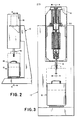
- Fig. 2 is a side view of apparatus constructed in accordance with the invention;
- Fig. 3 is an enlarged cross-section taken along the line 3-3 of Fig. 2;
- Fig. 4 is an enlarged cross-section taken substantially along the line 4-4 of Fig. 3;
- Fig. 5 is an enlarged cross-section taken substantially along the line 5-5 of Fig. 4;
- Fig. 6 is an enlarged cross-section taken substantially along the line 6-6 of Fig. 4; and
- Fig. 7 illustrates the construction of the magnetic core of the linear variable differential transformer which forms part of the invention.
- With particular reference to Fig. 2, there is illustrated an apparatus in accordance with the invention comprising a
stand 10 upon which is positioned a furnace andheat exchanger assembly 12. This assembly is similar to that of the above-referenced prior art patent and includes an electrically heatedfurnace 14. The assembly may be cooled by liquid nitrogen and the furnace may be heated. In this fashion theassembly 12 may be programmed through a range of temperatures from -180°C to 1000°C. - Suspended above the furnace-
heat exchanger assembly 12 is ahousing 16 from which depends aquartz furnace tube 18. Theassembly 12 may be raised into a position as illustrated by the dashed lines where it will receive thefurnace tube 18. As this feature is similar to that of the referenced prior art patent it will not be disclosed in detail. - Mounted on the
stand 10 is abracket 20 as may be most clearly seen in Fig. 4, Thebracket 20 includes acentral opening 22 upon which is positioned amounting ring 24 by means of screws (not shown). Extending downwardly from themounting ring 24 through the opening 22 is acylinder 26 which has a number of cut-outs 28 in its side wall and carries three outwardly radially spacedmounting lugs 30 on its lower end. The upper surface ofmounting ring 24 has a circular ring-shapedtapered seat 32. The surface of theseat 32 is ideally a portion of the surface of a sphere. For practical purposes it may be conical. Seated upon theseat 32 is the outer lower edge of abearing ring 34 of rectangular cross-section.Bearing ring 34 is mounted to the bottom of acylindrical magnet assembly 36. Four adjustingscrews 38 are threaded into mountingring 24 with their tapered heads bearing against the upper edge of thebearing ring 34. - Suspended from the
lugs 30 by means ofscrews 40 is acylindrical aluminum housing 42. Thehousing 42 includes acentral opening 44 within which is mounted a conventional linear variable differential transformer (LVDT) 46. Thehousing 42 also includes a pair of diametrically positioned parallel wells which containcartridge heaters 48. Temperature control is maintained by asensor 50 mounted in the side of thehousing 42. - Suspended from the bottom of the
housing 42 is achamber 52. As will be seen from Fig. 5,chamber 52 includes anupper wall 54 which is substantially cylindrical for something more than 180° but is formed to provide a pair of spaced parallelvertical side walls 56. Mounted between theside walls 56 is alatch 58 which is in the form of a cylinder having a cut-out 60. Latch 58 is retained at one end by an enlargedhead 62 and at the other by an L-shaped actuating level 64. Protruding inwardly from thecylindrical wall 54 is aboss 66 which defines aport 68 communicating with the end of a scavenginggas delivery tube 70. - Depending from
chamber 52 is achuck 72 comprising an externally threadedmale stud 74 and an internally threadedfemale clamp 76. These members cooperate in the usual manner to secure the tapered upper end ofquartz furnace tube 18. This tube is similar to that disclosed in the above-referenced prior art patent and includes at its lower end a pair of alignedopenings 80 and asample support surface 82. - Returning now to the upper end of the apparatus, the
magnet assembly 36 comprises one element of a linear motor. It comprises an ironouter cylinder 84 and a coaxial ironinner cylinder 86 which are joined at their upper ends by a magneticallypermeable plate 88. The space betweenouter cylinder 84 andinner cylinder 86 is occupied by three permanentceramic magnets 90 polarized such that thecylinders - The air gap remaining between the
permanent magnets 90 and theinner cylinder 86 is occupied by acylindrical aluminum armature 92 which is movable up and down within the air gap. Thearmature 92 carries acoil 94 comprising a few turns of wire around its upper end which are connected to external terminals by very thin leads 96. The lower end of thearmature 92 is secured to anon-magnetic actuator rod 98. The upper end ofrod 98 carries asmall weight tray 100. - At either end of the
housing 42 therod 98 passes through a bearingassembly ring 106. The O-rings are very slightly larger than theactuator rod 98 so that they are essentially frictionless when therod 98 is exactly vertical. - A portion of the
rod 98 which is within theLVDT 46 has a reduceddiameter portion 108 as will be seen in Fig. 7. Mounted upon this portion is the tubularmagnetic core 110 of the LVDT. Thecore 110 is secured to therod 98 as byepoxy 112 at only one end. In this manner thecore 110 androd 98 are free to expand and contract in response to temperature changes and magnetostrictive effects without the creation of mutual stresses. - The lower end of
rod 98 carries aprobe support member 114. Themember 114 includes anupper shoulder 116 which is of a size to just fit within the inner diameter of thestud 74. It carries apin 118 which extends between the two side walls 56 (Fig. 5) of thechamber 52. The lower end ofprobe support member 114 is drilled and tapped to receive a threadedmetal stud 120 which is secured to the end of each of the quartz probes 122 which the apparatus may employ. - The linear motor control system is illustrated in Fig. 1. A voltage controlled high impedance
current source 124 supplies thelinear motor 126. Control voltage is applied to thesource 124 through a twoposition switch 128 having normally closed (NC) and normally open (NO) contacts as illustrated.Switch 128 is controlled by a flip-flop 130. - When the user desires to insert a sample between the
sample support surface 82 and the lower end ofprobe 122, a switch is closed to initiate an "up" command to raise the probe. This actuates the flip-flop 130 which moves theswitch 128 to close it normally open contact. The force output of themotor 126 is added algebraically to the probe weight and a calibrating weight, the calibrating weight being positioned upontray 100. The resulting force ( F) is affected by the transfer function of the mechanical system labelled "probe". The transfer function is defined by the viscous friction coefficient D and the mass M. The 1/S term in the transfer function represents integration since there is no restoring force (or spring constant) in the system. - The position of the shaft Ym is sensed by the
LVDT 46 which generates a voltage Vm. This voltage is compared with a set-point voltage Vs and the error voltage V is amplified byamplifier 132 and controls the linear motor, thus closing the loop. The force output oflinear motor 126 becomes whatever is required to raise theprobe 122 in response to the Vs ramp generator 134. The input voltage VMO is sampled and stored in memory while the system is in this closed loop mode. - The position input voltage Vs continues to increase until it reaches a value corresponding to a probe displacement of approximately 3 cms, permitting the user to adjust or replace a sample. A "down" command is then given. Vs starts to decrease and the probe descends. When the probe touches the sample the amplified error voltage KA V starts to decrease very rapidly. When this voltage equals a predetermined voltage corresponding to a load slightly less than the probe weight, as determined by
comparator 136 the flip-flop 130 returns switch 128 to its normally closed position. The motor is then controlled by the VMA input signal which is equal to the VMO signal previously measured and stored. Thus, the probe comes to rest on the sample with negligible force and thereafter tracks any dimensional changes in the sample. - The apparatus of this invention includes a number of important features in addition to those previously decribed. For example, in order to provide more accurate measurements free from the effect of changes in mounting dimensions, the entire assembly is suspended from one point on the
bracket 20. As will be seen from Fig. 4, the entire "analytical train" is supported on the taperedseat 32. - Friction on the shaft which could contribute errors to the force measurement is substantially eliminated by the use of the Teflon rings previously described. Any residual lateral forces caused by assymmetry in the
magnet assembly 36 can be nulled by deliberately altering the angle between the magnet axis and therod 98. This is done by rotation of the adjusting screws 38 to slightly alter the relationship between the bearingring 34 and the taperedseat 32. - The force generated by the linear motor is proportional to the current in the
coil 94 and to the magnetic field strength. By employing a high impedance constant current source for driving thecoil 94 it is unnecessary to make corrections for any self-heating of the coil. Thealuminum armature 92 upon which the coil is wound behaves as a shorted turn. This provides electro-magnetic damping when the system is in the closed loop levitation mode described previously. - The system compensates for the weight of the shaft by measuring the coil current required to lift the probe assembly. As previously explained, this is initiated by the user when introducing a new sample. When the probe is lowered, the instrument automatically weighs the probe assembly until it rests on the sample. At this point a restoring force equal to the measured probe weight is generated by the motor so that there is negligible force on the sample. The LVDT adjustment provided by the rack and pinion of the prior art device is avoided by a longer LVDT which may be operated away from its null-point. Normally, when an LVDT is so operated, its output is temperature dependent. However, this is avoided in the instrument of the invention by the temperature control provided by the
cartridge heaters 48 andsensor 50. - In order to change a probe the
furnace tube 18 is removed by unscrewing theclamp 76. When the furnace tube is removed theprobe 122, which was formerly supported by thesupport surface 82, drops and thepin 118 comes to rest on the floor of thechamber 52, passing through thecutout 60 of thelatch 58. Thelever 64 is then raised so as to position thelatch 58 over thepin 118, temporarily clamping it in place. Theprobe 122 is then unscrewed and a new probe connected. In order to avoid damage or strain to portions of the assembly as, for example, to the wire leads 96, any rotation caused by threading the probe into or out of place is avoided by thepin 118 which is prevented from rotating more than permitted by the side walls 56 (Fig. 5).
Claims (11)
- A thermomechanical analysis apparatus of the type which includes a support (82) for positioning a sample in a programmable temperature environment; a vertically displaceable probe (122) positionable in contact with the sample surface; means for substantially offsetting the effect of the weight of the probe (122) on the sample; and means (46) for monitoring movement of the probe (122) in response to changing physical characteristics of said sample, in which said weight offsetting means is a linear motor comprising:
a substantially cylindrical magnet assembly (36);
a linearly, vertically, movable armature (92) coaxial with said magnet assembly (36) and including a coil (94) energizable to generate a magnetic field operable with the field of said magnet assembly (36) to exert a vertical axial force on said armature (92); and
means (124) for controllably energizing said coil (94) with an electrical current,
characterised in that said weight offsetting means supports said probe (122) and
said substantially cylindrical magnet assembly (36) is mounted above and is coaxial with said probe (122). - The apparatus of claim 1 wherein said armature (92) is electrically conductive and forms a shorted secondary turn to said coil (94).
- The apparatus of claim 1 wherein said coil energizing means is a circuit comprising:
a high impedance current source (124);
a probe position sensor (46) and a set point control (134);
means responsive to the outputs (Vm,Vs) of said position sensor (46) and said point control (134) to generate an error signal (AV);
switching means (130,SW1) having a first function for energizing said coil (94) in response to said error signal (AV) in a closed loop mode to lift said probe and a second function for energizing said coil (94) in response to a control signal external of said loop;
means (VMO) responsive to the value of said error signal (AV) while in the closed loop mode to store said error signal value; and
means (VMA) responsive to the stored error signal to energize said coil (94) in response to said external source by an amount proportional to said stored error signal value. - The apparatus of claim 3 wherein said probe position sensor (46) is a linear variable differential transformer (LVDT).
- The apparatus of claim 4 wherein said probe support means is a non-magnetic vertical rod (98) depending from said armature (92) and said linear variable differential transformer (LVDT) comprises:
a substantially cylindrical, hollow coil housing (42) surrounding said vertical rod (98);
a magnetic coil (110) within said coil housing (42); and
means (112) securing said core (110) to said vertical rod (98) for permitting expansion and contraction of each of said core (110) and rod (98) without inducing strain therebetween. - The apparatus of claim 5 wherein said core (110) comprises a tube surrounding said rod (108) expandable and contractible therealong, and secured to said rod (98) at substantially one location along their lengths.
- The apparatus of claim 5 wherein said coil housing (42) includes temperature control means (48,50).
- The apparatus of claim 7 wherein said temperature control means (48,50) comprises an electrical heater (48).
- The apparatus of claim 1 wherein said magnet assembly (36) includes mount means (32,34,38) for adjusting the vertical alignment of the axis of said cylindrical magnet assembly (36).
- The apparatus of claim 9 wherein said mount means (32,34,38) comprises:
a support member (24) having a substantially circular, ring shaped, tapered seat (32) symmetrical about a vertical axis;
a bearing ring (34) carried by said magnet assembly (36) and positionable on said seat (32); and
clamping means (38) for adjustably positioning and clamping said bearing ring (34) relative to said seat (32). - The apparatus of claim 10 wherein said thermomechanical analysis apparatus is suspended substantially entirely from said support member (24).
Applications Claiming Priority (2)
| Application Number | Priority Date | Filing Date | Title |
|---|---|---|---|
| US704353 | 1985-02-21 | ||
| US06/704,353 US4896973A (en) | 1985-02-21 | 1985-02-21 | Thermomechanical analysis apparatus |
Publications (3)
| Publication Number | Publication Date |
|---|---|
| EP0192238A2 EP0192238A2 (en) | 1986-08-27 |
| EP0192238A3 EP0192238A3 (en) | 1987-10-28 |
| EP0192238B1 true EP0192238B1 (en) | 1991-06-05 |
Family
ID=24829123
Family Applications (1)
| Application Number | Title | Priority Date | Filing Date |
|---|---|---|---|
| EP86102068A Expired EP0192238B1 (en) | 1985-02-21 | 1986-02-18 | Thermomechanical analysis apparatus |
Country Status (4)
| Country | Link |
|---|---|
| US (1) | US4896973A (en) |
| EP (1) | EP0192238B1 (en) |
| JP (1) | JPH0781968B2 (en) |
| DE (1) | DE3679571D1 (en) |
Families Citing this family (9)
| Publication number | Priority date | Publication date | Assignee | Title |
|---|---|---|---|---|
| JPH0185607U (en) * | 1987-11-30 | 1989-06-07 | ||
| JPH02119576A (en) * | 1987-12-25 | 1990-05-07 | Mitsui Petrochem Ind Ltd | Pulse power unit |
| EP0710327B1 (en) * | 1993-07-13 | 1997-05-07 | UHP Corporation | High pressure pump system and method of operation thereof |
| JP3026149B2 (en) * | 1995-07-11 | 2000-03-27 | セイコーインスツルメンツ株式会社 | Thermomechanical analyzer with thermogravimetry function |
| US6511221B1 (en) * | 1999-10-19 | 2003-01-28 | Agere Systems Inc. | Apparatus for measuring thermomechanical properties of photo-sensitive materials |
| RU2178884C1 (en) * | 2001-01-23 | 2002-01-27 | Архипов Геннадий Викторович | Installation to examine physical and mechanical properties of coal products |
| US7835778B2 (en) * | 2003-10-16 | 2010-11-16 | Medtronic Navigation, Inc. | Method and apparatus for surgical navigation of a multiple piece construct for implantation |
| US20130047741A1 (en) * | 2011-08-27 | 2013-02-28 | Lecon Woo | Method and Apparatus for Direct-Acting Wide Frequency Range Dynamic Mechanical Analysis of Materials |
| US11187677B1 (en) * | 2021-03-17 | 2021-11-30 | Wesley Nelson Cobb | Combined ultrasonic and thermomechanical property measurement |
Family Cites Families (7)
| Publication number | Priority date | Publication date | Assignee | Title |
|---|---|---|---|---|
| US3474658A (en) * | 1966-05-12 | 1969-10-28 | Du Pont | Thermomechanical analyzer |
| US3589167A (en) * | 1969-07-07 | 1971-06-29 | Perkin Elmer Corp | Thermomechanical analysis apparatus |
| US3680357A (en) * | 1970-09-21 | 1972-08-01 | Gerhard R Clusener | Dilatometer |
| DE2331113C2 (en) * | 1973-06-19 | 1975-05-22 | W.C. Heraeus Gmbh, 6450 Hanau | Dilatometer |
| US4019365A (en) * | 1975-03-04 | 1977-04-26 | E. I. Du Pont De Nemours And Company | Thermomechanical analyzer |
| CH648126A5 (en) * | 1980-06-13 | 1985-02-28 | Mettler Instrumente Ag | DEVICE FOR THERMAL ANALYTICAL MEASUREMENTS. |
| DE3137603C2 (en) * | 1981-09-22 | 1983-11-17 | Bodenseewerk Perkin-Elmer & Co GmbH, 7770 Überlingen | Device for performing thermomechanical analyzes |
-
1985
- 1985-02-21 US US06/704,353 patent/US4896973A/en not_active Expired - Fee Related
-
1986
- 1986-02-17 JP JP61031035A patent/JPH0781968B2/en not_active Expired - Lifetime
- 1986-02-18 EP EP86102068A patent/EP0192238B1/en not_active Expired
- 1986-02-18 DE DE8686102068T patent/DE3679571D1/en not_active Expired - Lifetime
Also Published As
| Publication number | Publication date |
|---|---|
| EP0192238A3 (en) | 1987-10-28 |
| EP0192238A2 (en) | 1986-08-27 |
| DE3679571D1 (en) | 1991-07-11 |
| US4896973A (en) | 1990-01-30 |
| JPS61201146A (en) | 1986-09-05 |
| JPH0781968B2 (en) | 1995-09-06 |
Similar Documents
| Publication | Publication Date | Title |
|---|---|---|
| US5311125A (en) | Magnetic property characterization system employing a single sensing coil arrangement to measure AC susceptibility and DC moment of a sample | |
| US2293502A (en) | Electric measuring apparatus | |
| US4896973A (en) | Thermomechanical analysis apparatus | |
| EP0144437A1 (en) | Rheometer | |
| EP1482320A2 (en) | Temperature stabilised shimming of an MRI system | |
| US4643586A (en) | Equipment and method for calibration of instruments having a temperature sensing unit | |
| US2362661A (en) | Telemetric system | |
| JPS6122231A (en) | Micro-hardness test apparatus | |
| US4034819A (en) | Electromagnetic compensating balance | |
| US3554001A (en) | Thermal gravimetric analysis apparatus | |
| US3589167A (en) | Thermomechanical analysis apparatus | |
| JPS6318914Y2 (en) | ||
| US4774458A (en) | Magnetic device | |
| US2992561A (en) | Force measuring instrument | |
| CN119714487A (en) | Magnetic suspension balance and control method thereof | |
| GB2035566A (en) | Thickness measuring apparatus | |
| US3388585A (en) | Fluid density measuring apparatus | |
| US4548515A (en) | Multiple sensor dilatometer | |
| SU1696844A1 (en) | Device for measurement of material sample linear dimensions | |
| US3665296A (en) | Susceptibility meter for field use for determining susceptibility of a rock outcrop | |
| CN113042126A (en) | Supporting leg device with oil bath for adjusting micro inclination of platform | |
| SU1033849A1 (en) | Linear displacement pickup | |
| US4561285A (en) | Thermally isolated calibration apparatus | |
| RU2849315C1 (en) | Device for determining the thermal stability of substances | |
| US3054296A (en) | Apparatus for specific gravity measurements |
Legal Events
| Date | Code | Title | Description |
|---|---|---|---|
| PUAI | Public reference made under article 153(3) epc to a published international application that has entered the european phase |
Free format text: ORIGINAL CODE: 0009012 |
|
| AK | Designated contracting states |
Kind code of ref document: A2 Designated state(s): CH DE FR GB LI NL |
|
| PUAL | Search report despatched |
Free format text: ORIGINAL CODE: 0009013 |
|
| AK | Designated contracting states |
Kind code of ref document: A3 Designated state(s): CH DE FR GB LI NL |
|
| 17P | Request for examination filed |
Effective date: 19880427 |
|
| 17Q | First examination report despatched |
Effective date: 19891211 |
|
| GRAA | (expected) grant |
Free format text: ORIGINAL CODE: 0009210 |
|
| AK | Designated contracting states |
Kind code of ref document: B1 Designated state(s): CH DE FR GB LI NL |
|
| REF | Corresponds to: |
Ref document number: 3679571 Country of ref document: DE Date of ref document: 19910711 |
|
| ET | Fr: translation filed | ||
| PLBE | No opposition filed within time limit |
Free format text: ORIGINAL CODE: 0009261 |
|
| STAA | Information on the status of an ep patent application or granted ep patent |
Free format text: STATUS: NO OPPOSITION FILED WITHIN TIME LIMIT |
|
| 26N | No opposition filed | ||
| REG | Reference to a national code |
Ref country code: GB Ref legal event code: 732E |
|
| PGFP | Annual fee paid to national office [announced via postgrant information from national office to epo] |
Ref country code: GB Payment date: 20010202 Year of fee payment: 16 |
|
| PGFP | Annual fee paid to national office [announced via postgrant information from national office to epo] |
Ref country code: FR Payment date: 20010222 Year of fee payment: 16 |
|
| PGFP | Annual fee paid to national office [announced via postgrant information from national office to epo] |
Ref country code: NL Payment date: 20010227 Year of fee payment: 16 |
|
| PGFP | Annual fee paid to national office [announced via postgrant information from national office to epo] |
Ref country code: CH Payment date: 20010302 Year of fee payment: 16 |
|
| PGFP | Annual fee paid to national office [announced via postgrant information from national office to epo] |
Ref country code: DE Payment date: 20010329 Year of fee payment: 16 |
|
| REG | Reference to a national code |
Ref country code: GB Ref legal event code: IF02 |
|
| PG25 | Lapsed in a contracting state [announced via postgrant information from national office to epo] |
Ref country code: GB Free format text: LAPSE BECAUSE OF NON-PAYMENT OF DUE FEES Effective date: 20020218 |
|
| PG25 | Lapsed in a contracting state [announced via postgrant information from national office to epo] |
Ref country code: LI Free format text: LAPSE BECAUSE OF NON-PAYMENT OF DUE FEES Effective date: 20020228 Ref country code: CH Free format text: LAPSE BECAUSE OF NON-PAYMENT OF DUE FEES Effective date: 20020228 |
|
| PG25 | Lapsed in a contracting state [announced via postgrant information from national office to epo] |
Ref country code: NL Free format text: LAPSE BECAUSE OF NON-PAYMENT OF DUE FEES Effective date: 20020901 |
|
| PG25 | Lapsed in a contracting state [announced via postgrant information from national office to epo] |
Ref country code: DE Free format text: LAPSE BECAUSE OF NON-PAYMENT OF DUE FEES Effective date: 20020903 |
|
| GBPC | Gb: european patent ceased through non-payment of renewal fee |
Effective date: 20020218 |
|
| REG | Reference to a national code |
Ref country code: CH Ref legal event code: PL |
|
| PG25 | Lapsed in a contracting state [announced via postgrant information from national office to epo] |
Ref country code: FR Free format text: LAPSE BECAUSE OF NON-PAYMENT OF DUE FEES Effective date: 20021031 |
|
| NLV4 | Nl: lapsed or anulled due to non-payment of the annual fee |
Effective date: 20020901 |
|
| REG | Reference to a national code |
Ref country code: FR Ref legal event code: ST |