EP0192172B1 - Arrangement for studying the movement of a runner - Google Patents
Arrangement for studying the movement of a runner Download PDFInfo
- Publication number
- EP0192172B1 EP0192172B1 EP86101737A EP86101737A EP0192172B1 EP 0192172 B1 EP0192172 B1 EP 0192172B1 EP 86101737 A EP86101737 A EP 86101737A EP 86101737 A EP86101737 A EP 86101737A EP 0192172 B1 EP0192172 B1 EP 0192172B1
- Authority
- EP
- European Patent Office
- Prior art keywords
- signal
- receiver
- transmitter
- time
- equipment
- Prior art date
- Legal status (The legal status is an assumption and is not a legal conclusion. Google has not performed a legal analysis and makes no representation as to the accuracy of the status listed.)
- Expired
Links
Images

Classifications
-
- A—HUMAN NECESSITIES
- A43—FOOTWEAR
- A43B—CHARACTERISTIC FEATURES OF FOOTWEAR; PARTS OF FOOTWEAR
- A43B5/00—Footwear for sporting purposes
-
- A—HUMAN NECESSITIES
- A43—FOOTWEAR
- A43B—CHARACTERISTIC FEATURES OF FOOTWEAR; PARTS OF FOOTWEAR
- A43B5/00—Footwear for sporting purposes
- A43B5/06—Running shoes; Track shoes
-
- A—HUMAN NECESSITIES
- A43—FOOTWEAR
- A43B—CHARACTERISTIC FEATURES OF FOOTWEAR; PARTS OF FOOTWEAR
- A43B3/00—Footwear characterised by the shape or the use
- A43B3/34—Footwear characterised by the shape or the use with electrical or electronic arrangements
-
- A—HUMAN NECESSITIES
- A43—FOOTWEAR
- A43B—CHARACTERISTIC FEATURES OF FOOTWEAR; PARTS OF FOOTWEAR
- A43B3/00—Footwear characterised by the shape or the use
- A43B3/34—Footwear characterised by the shape or the use with electrical or electronic arrangements
- A43B3/44—Footwear characterised by the shape or the use with electrical or electronic arrangements with sensors, e.g. for detecting contact or position
-
- A—HUMAN NECESSITIES
- A43—FOOTWEAR
- A43B—CHARACTERISTIC FEATURES OF FOOTWEAR; PARTS OF FOOTWEAR
- A43B3/00—Footwear characterised by the shape or the use
- A43B3/34—Footwear characterised by the shape or the use with electrical or electronic arrangements
- A43B3/48—Footwear characterised by the shape or the use with electrical or electronic arrangements with transmitting devices, e.g. GSM or WiFi
-
- G—PHYSICS
- G01—MEASURING; TESTING
- G01C—MEASURING DISTANCES, LEVELS OR BEARINGS; SURVEYING; NAVIGATION; GYROSCOPIC INSTRUMENTS; PHOTOGRAMMETRY OR VIDEOGRAMMETRY
- G01C22/00—Measuring distance traversed on the ground by vehicles, persons, animals or other moving solid bodies, e.g. using odometers, using pedometers
- G01C22/006—Pedometers
-
- Y—GENERAL TAGGING OF NEW TECHNOLOGICAL DEVELOPMENTS; GENERAL TAGGING OF CROSS-SECTIONAL TECHNOLOGIES SPANNING OVER SEVERAL SECTIONS OF THE IPC; TECHNICAL SUBJECTS COVERED BY FORMER USPC CROSS-REFERENCE ART COLLECTIONS [XRACs] AND DIGESTS
- Y10—TECHNICAL SUBJECTS COVERED BY FORMER USPC
- Y10S—TECHNICAL SUBJECTS COVERED BY FORMER USPC CROSS-REFERENCE ART COLLECTIONS [XRACs] AND DIGESTS
- Y10S482/00—Exercise devices
- Y10S482/901—Exercise devices having computer circuitry
- Y10S482/902—Employing specific graphic or video display
Definitions
- the present invention relates to a system for determining the movement sequences in running disciplines with two shoes, in each of which a ground contact or pressure sensor is provided.
- a system known from US-A-4,371,945 consists of an ultrasound generator attached to one foot, an ultrasound detector attached to the other foot with a high-frequency transmitter and an RF receiver and processor carried on the arm. After switching on, the ultrasound generator continuously emits a constant pulse chain of constant pulse width and pause. The ultrasound detector receives these signals as the feet move past one another, with the pulse pauses being compressed or stretched when the pulse train is received and emitted again. From this, the desired run data are calculated according to the algorithms entered into the processor. In particular, flight or jump phases can only be included empirically in the calculation.
- pressure sensors are provided in the shoes, which transmit a signal as long as the shoe in question has contact with the ground. This signal is sent to a processor.
- An algorithm must also be entered into the processor so that it can determine the step size from the ground contact time and calculate the running distance. The step length associated with the ground contact time must be determined beforehand for each person.
- the object of the present invention is to design the system of the type mentioned at the outset in such a way that it is possible to measure the actual step size with the greatest possible accuracy, regardless of the running speed and taking into account a possible flight phase.
- the invention makes it possible to measure the step size between the lifting foot and the impacting foot extremely precisely with relatively little effort and to determine, for example, the distance traveled on the basis of these measured values.
- Fig. 1 represents a first device which is provided in one shoe 2 (Fig. 2), hereinafter referred to as the shoe of the rear foot hF, for example.
- Fig. 2 hereinafter referred to as the shoe of the rear foot hF, for example.
- a second device 4 is provided, which is assigned to the front foot vF in the example.
- the first device 1 contains a first ground contact or pressure sensor 5, which can be designed as a switching contact.
- This pressure sensor 5 is mounted in the shoe 2 so that it closes or opens a circuit when the sole of the shoe or the heel of the shoe 2 is lifted off.
- the conductor 6 coming from the pressure sensor 5 leads to a logic 7, which processes a pulse from the sensor signal, which is fed to a first transmitter 8 and which is preferably output in a modulated form as the first signal S1.
- HFHF high-frequency transmitter
- the first device 1 contains a first receiver 10 for acoustic and / or electromagnetic waves.
- the receiver 10 is designed as an ultrasound receiver US E , to which a corresponding sensor 11, ie here an ultrasound transducer, for example a type of microphone capsule, a piezo transducer or the like, is assigned.
- a received third signal S3 which will be explained later, passes from the ultrasound receiver 10 to the logic 7, which generates a reception pulse of a certain duration, for example. from 50 iLs to 1,000 ⁇ s, in particular 200 ⁇ s to 400 ⁇ s.
- This received pulse is fed to the first transmitter 8 or another transmitter provided in the shoe 2 and is emitted by the latter in the form of a fourth signal S4, in particular a modulated signal.
- the individual building blocks 7, 8, 10 - possibly also 5 and 9 - can be combined to form a structural unit and thus be accommodated in the shoe 2 as a compact element.
- the second device 4 contains a second pressure sensor 12 of the same or similar construction as the first pressure sensor 5.
- a voltage is applied to a logic 15 via a line 13 when the shoe 3 containing the device 4 strikes a substrate 14 (FIG. 2). or switched off.
- the logic 15 forms a control pulse therefrom, which is passed to a second transmitter 16, which is likewise designed here as a high-frequency transmitter HF vF, and is emitted by the latter via a suitable coupling element, for example an antenna 17, as a second signal S2 in a particularly modulated form.
- the control pulse is emitted via a further second transmitter 18 and an associated decoupling element 19 as a third signal S3.
- the second is the second Transmitter 18 is an ultrasound transmitter US S and the decoupling element 19 is an ultrasound transmitter, for example a type of microphone capsule, a piezo element or the like.
- the third signal S3 is therefore an ultrasound signal. As described at the beginning, this is received by the ultrasonic sensor 11 in the device 1 and emitted via the first transmitter 8 as a fourth signal S4. Since the two shoes 2 and 3 have a foot distance FA corresponding to the respective position of the feet hF and vF at the moment the front shoe 3 strikes, the third signal S3 requires a running time LZ corresponding to the foot distance. The fourth signal S4 is then also delayed by this runtime compared to the third signal S3.
- the system is assigned a third device 20 with a second receiver 21, which can be worn in the hand or in clothing, in particular by the runner.
- the receiver 21 is able to receive and process the signals S1, S2 and S4 via an antenna 22.
- this is a high-frequency receiver HF E , which demodulates the modulated signals S1, S2, S4 and feeds the pulses obtained to a timer, which in this case is integrated in an associated microcomputer 23 serving as an evaluation unit.
- the latter contains at least one, in particular programmable, memory and a computing unit.
- the microprocessor can, for example, the foot distance FA and the respective step size, and calculate the distance traveled and the respective or average speed from it. This is done as follows:
- the signal S1 is generated. Since it is an RF signal in the exemplary embodiment, it is also referred to as HFhF.
- the front shoe 3 strikes the ground 14 and outputs the signals S2, here as an HF signal HFF, and S3, here as an ultrasonic signal US vF from the ultrasonic transmitter 18, simultaneously or at least almost simultaneously.
- the latter signal S3 is received delayed by the transit time LZ as a delayed third signal S3, and thereby the fourth signal S4 is broadcast by the first senter 8 in the shoe 2 of the rear foot hF.
- the second receiver 21 thus receives the first signal S1 at the start time TA , the second signal S2 after the jump time t o and the fourth signal S4 after the runtime LZ. After a while, a first signal S1 'comes again, after the further jump time t o ' the following second signal S2 'etc.
- the time interval between two successive second signals S2 and S2' corresponds to the time of two steps and is here with 2t Referred to Sch
- This speed component can be defined as step size SW per step time t Sch , ie:
- the step width SW having a transition phase additionally results from the foot spacing FA (without taking into account the angular position of the distance from the FA to the substrate 14), the path portion, which in the jump phase, ie in the time t o, kilometer. This results in the approximately exact step size and by conversion:
- step size SW is equal to the foot distance FA.
- the angular position of the route from FA to the subsurface 14 can also be taken into account as a constant. Accordingly, the measured step time 2t sch from the time interval S2-S2 'must be included in the calculation in half.
- the received and / or ascertained values, such as step size SW, foot distance FA, total running distance, total time and any intermediate results can be obtained from the microcumputer 23 depending on the program input output as a signal code and / or, for example, a display or a display 24 are supplied.
- a surface electrode 26 is provided on the insole 25 of each shoe 2, 3, in particular in the heel area and / or in the forefoot area. This is in each case connected or electrically coupled to the output electrode of a first or second transmitter 8 or 16 which emits electromagnetic radiation in the wavelength range up to a few GHz.
- the body of the rotor is used as a coupling-out element, for example as an antenna.
- transmitters can be used that have a very low output power, but the function of the system is nevertheless ensured.
- disturbances between people running in close proximity are practically excluded.
- the distance traveled, the instantaneous and average speed can be determined by the evaluation device 23. However, variables that can be derived from this, for example the calorie consumption, can also be determined and displayed.
- Memory 23 can also be provided in the evaluation device for storing the received signals and / or the determined intermediate and / or final results.
- the system according to the invention is particularly advantageous in sports shoes for running disciplines with a sensor provided in the shoe sole of a shoe, which emits a signal when it occurs, and a transmitter which emits radiation corresponding to the signal, which is received by a location-independent receiver, in accordance with the older European one Patent application application number 851012195 EP-A-0 152 057, published on 08/21/85.
- a receiver or a transceiver is provided in a shoe, which receives the radiation emitted by the transmitter of the other shoe of the runner.
- the distance between the two shoes and thus the stride length when or shortly after the shoe provided with the transmitter occurs can be determined via an assigned computer from the signal emitted by the transmitter or the corresponding radiation and from the radiation received by the receiver.
- the method protected in this earlier application is characterized in that when the front shoe hits the floor, an output signal is emitted by the transmitter of this shoe and emitted in such a way that it is received both by a receiver provided on the body of the athlete and by the receiver of the rear shoe can be received.
- the reception of the output signal by the receiver in the rear shoe causes the transmitter in the rear shoe to emit an output signal in such a way that it can either be received directly by the receiver provided on the body of the athlete or via the front shoe as a relay station.
- the leg or running speed and / or the step size of the athlete is determined by means of an arithmetic unit assigned to the receiver and output via an optical display and / or an acoustic transducer.
Abstract
Description
Die vorliegende Erfindung bezieht sich auf eine Anlage zur Ermittlung der Bewegungsabläufe bei Laufdisziplinen mit zwei Schuhen in denen jeweils ein Bodenkontakt- oder Drucksensor vorgesehen ist.The present invention relates to a system for determining the movement sequences in running disciplines with two shoes, in each of which a ground contact or pressure sensor is provided.
Eine aus der US-A-4 371 945 bekannte Anlage besteht aus einem an einem Fuß angebrachten Ultraschallgenerator, einem am anderen Fuß angebrachten Ultraschalldetektor mit Hochfrequenzsender und einem am Arm getragenen HF-Empfänger und Prozessor. Der Ultraschallgenerator gibt nach Einschalten dauernd eine konstante Impulskette konstanter Pulsbreite und Pulspause ab. Der Ultraschalldetektor empfängt diese Signale beim Vorbeibewegen der Füße aneinander, wobei bei der empfangenen und wieder abgestrahlten Impulskette die Pulspausen komprimiert oder gedehnt werden. Hieraus werden nach den dem Prozessor eingebenen Algorithmen die gewünschten Laufdaten berechnet. Hierbei können insbesondere auch Flug- oder Sprungphasen nur empirisch in die Berechnung mit einbezogen werden.A system known from US-A-4,371,945 consists of an ultrasound generator attached to one foot, an ultrasound detector attached to the other foot with a high-frequency transmitter and an RF receiver and processor carried on the arm. After switching on, the ultrasound generator continuously emits a constant pulse chain of constant pulse width and pause. The ultrasound detector receives these signals as the feet move past one another, with the pulse pauses being compressed or stretched when the pulse train is received and emitted again. From this, the desired run data are calculated according to the algorithms entered into the processor. In particular, flight or jump phases can only be included empirically in the calculation.
Bei einer aus der EP-A-0 119 009 bekannten Anlage sind in den Schuhen Drucksensoren vorgesehen, die so lange ein Signal aussenden, solange der betreffende Schuh Bodenkontakt hat. Dieses Signal wird einem Prozessor zugesendet. Dem Prozessor muß ebenfalls ein Algorithmus eingegeben werden, so daß er aus der Bodenkontaktzeit die Schrittweite ermitteln und die Laufstrecke berechnen kann. Dabei muß vorher für jede Person die zur Bodenkontaktzeit gehörige Schrittlänge ermittelt werden.In a system known from EP-A-0 119 009, pressure sensors are provided in the shoes, which transmit a signal as long as the shoe in question has contact with the ground. This signal is sent to a processor. An algorithm must also be entered into the processor so that it can determine the step size from the ground contact time and calculate the running distance. The step length associated with the ground contact time must be determined beforehand for each person.
Mit der vorliegenden Erfindung soll die Aufgabe gelöst werden, die Anlage der eingangs erwähnten Art so auszubilden, daß es möglich ist, die tatsächliche Schrittweite unabhängig von der Laufgeschwindigkeit und unter Berücksichtigung einer eventuellen Flugphase mit möglichst hoher Genauigkeit zu messen.The object of the present invention is to design the system of the type mentioned at the outset in such a way that it is possible to measure the actual step size with the greatest possible accuracy, regardless of the running speed and taking into account a possible flight phase.
Gelöst wird diese Aufgabe durch die im Anspruch 1 angegebenen Merkmale.This object is achieved by the features specified in
Die Erfindung ermöglicht es, die Schrittweite zwischen dem abhebenden Fuß und dem auftreffenden Fuß mit relativ geringem Aufwand äußerst genau zu messen und auf Grund dieser Meßwerte beispielsweise die gelaufene Wegstrecke zu ermitteln.The invention makes it possible to measure the step size between the lifting foot and the impacting foot extremely precisely with relatively little effort and to determine, for example, the distance traveled on the basis of these measured values.
Weitere vorteilhafte Einzelheiten der Erfindung sind in den Unteransprüchen enthalten und werden nachfolgend anhand eines in der Zeichnung veranschaulichten Ausführungsbeispiels näher beschrieben. Dabei zeigen :
- Fig. 1 ein Schema einer erfindungsgemäßen Anlage,
- Fig. 2 die Impulsdiagramme der von den einzelnen Schuhen ausgehenden bzw. empfangenen Signale sowie ein Impulsdiagramm der vom zweiten Empfänger aufgenommenen Signale,
- Fig. 3 ein Impulsdiagramm des zweiten Empfängers über einen Zeitabschnitt von zwei Schritten,
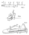
- Fig. 4 eine Bewegungsphase des Läufers und
- Fig. 5 einen für die Anlage gemäß
Figur 1 entwickelten Sportschuh, teilweise im Schnitt.
- 1 is a diagram of a plant according to the invention,
- 2 shows the pulse diagrams of the signals emitted or received by the individual shoes as well as a pulse diagram of the signals received by the second receiver,
- 3 shows a pulse diagram of the second receiver over a period of two steps,
- Fig. 4 shows a movement phase of the runner and
- 5 a sports shoe developed for the system according to FIG. 1, partly in section.
In Fig. 1 ist mit 1 eine erste Einrichtung dargestellt, die in dem einen Schuh 2 (Fig. 2), im weiteren beispielhaft als der Schuh des hinteren Fußes hF bezeichnet, vorgesehen ist. Im anderen Schuh 3 (Fig. 2) ist eine zweite Einrichtung 4 vorgesehen, die also im Beispiel dem vorderen Fuß vF zugeordnet ist.In Fig. 1, 1 represents a first device which is provided in one shoe 2 (Fig. 2), hereinafter referred to as the shoe of the rear foot hF, for example. In the other shoe 3 (FIG. 2) a
Die erste Einrichtung 1 enthält einen ersten Bodenkontakt- oder Drucksensor 5, der als Schaltkontakt ausgebildet sein kann. Dieser Drucksensor 5 ist in dem Schuh 2 so angebracht, daß er beim Abheben der Schuhsohle oder des Absatzes des Schuhes 2 einen Stromkreis schließt oder öffnet. Der vom Drucksensor 5 abgehende Leiter 6 führt zu einer Logik 7, die aus dem Sensorsignal einen Impuls aufbereitet, der einem ersten Sender 8 zugeleitet wird und von diesem vorzugsweise in modulierter Form als erstes Signal S1 ausgegeben wird.The
Im Ausführungsbeispiel ist er erste Sender 8 ein Hochfrequenzsender HFHF, der das modulierte Impulssignal S1, beispielsweise auch in digitaler Form, über eine geeignete Antenne 9 abstrahlt.In the exemplary embodiment, it is the
Weiterhin beinhaltet die erste Einrichtung 1 einen ersten Empfänger 10 für akustische und/oder elektromagnetische Wellen. Im Beispiel ist der Empfänger 10 als Ultraschallempfänger USE ausgebildet, dem ein entsprechender Sensor 11, also hier ein Ultraschallwandler, beispielsweise eine Art Mikrophonkapsel, ein Piezowandler oder dgl. zugeordnet ist. Vom Ultraschallempfänger 10 gelangt ein empfangenes drittes Signal S3, das später noch erläutert werden wird, an die Logik 7, die daraus einen Empfangsimpuls von bestimmter Zeitdauer, beispielsweise. von 50 iLs bis 1 000 µs, insbesondere 200 µs bis 400 µs, bildet. Dieser Empfangsimpuls wird dem ersten Sender 8 oder einem weiteren, im Schuh 2 vorgesehenen Sender zugeführt und von diesem in Form eines vierten Signals S4, insbesondere eines modulierten Signals, abgestrahlt. Die einzelnen Bausteine 7, 8, 10 - gegebenenfalls auch 5 und 9 - können zu einer baulichen Einheit zusammengefaßt und damit als Kompaktelement in dem Schuh 2 untergebracht sein.Furthermore, the
Die zweite Einrichtung 4 enthält einen zweiten Drucksensor 12 gleichen oder ähnlichen Aufbaues wie der erste Drucksensor 5. Über eine Leitung 13 wird beim Auftreffen des die Einrichtung 4 enthaltenden Schuhes 3 auf einen Untergrund 14 (Fig. 2) eine Spannung an eine Logik 15 an- oder abgeschaltet. Die Logik 15 bildet daraus einen Steuerimpuls, der an einen zweiten Sender 16, der hier ebenfalls als Hochfrequenzsender HFvF ausgebildet ist, geleitet und von diesem über ein geeignetes Koppelglied, beispielsweise eine Antenne 17, als zweites Signal S2 in insbesondere modulierter Form abgestrahlt wird. Außerdem wird der Steuerimpuls über einen weiteren zweiten Sender 18 und ein zugeordnetes Auskoppelelement 19 als drittes Signal S3 abgestrahlt. Im vorliegenden Falle ist der weitere zweite Sender 18 ein Ultraschallsender USS und das Auskoppelelement 19 ein Ultraschallgeber, beispielsweise eine Art Mikrophonkapsel, ein Piezoelement oder dgl. Das dritte Signal S3 ist also ein Ultraschallsignal. Dieses wird, wie eingangs beschrieben, vom Ultraschallsensor 11 in der Einrichtung 1 empfangen und über den ersten Sender 8 als viertes Signal S4 abgestrahlt. Da die beiden Schuhe 2 und 3 im Moment des Auftreffens des vorderen Schuhes 3 einen der jeweiligen Lage der Füße hF und vF entsprechenden Fußabstand FA aufweisen, benötigt das dritte Signal S3 eine dem Fußabstand entsprechende Laufzeit LZ. Um diese Laufzeit ist dann auch das vierte Signal S4 gegenüber dem dritten Signal S3 verzögert. Aus der Schallgeschwindigkeit und der Laufzeit kann daher der genaue Fußabstand FA im Zeitpunkt des Auftreffens des vorderen Fußes vF auf den Untergrund 14 ermittelt werden, da FA = VLuft · tLZ, wenn VLuft die Schallgeschwindigkeit in Luft und tLZ die obengenannte Laufzeit ist.The
Um die Signale S1, S2 und S4 empfangen und aus diesen die gewünschten Daten ermitteln zu können, ist der Anlage eine dritte Einrichtung 20 mit einem zweiten Empfänger 21 zugeordnet, die insbesondere vom Läufer in der Hand oder in der Kleidung getragen werden kann. Der Empfänger 21 ist in der Lage, die Signale S1, S2 und S4 über eine Antenne 22 zu empfangen und diese aufzubereiten. Im vorliegenden Falle ist dies ein Hochfrequenzempfänger HFE, der die modulierten Signale S1, S2, S4 demoduliert und die gewonnenen Impulse einem Zeitmesser zuleitet, der in diesem Fall in einem zugeordneten, als Auswerteeinheit dienenden Mikrocomputer 23 integriert ist. Letzterer enthält wenigstens einen, insbesondere programmierbaren, Speicher und eine Recheneinheit. Aus dem zeitlichen Abstand der einzelnen Signale, die für den hinteren Fuß hF, für den vorderen Fuß vF und für den zweiten Empfänger 21 anhand des in der Fig. 2 dargestellten Impulsdiagramms dargestellt sind, kann der Mikroprozessor beispielsweise den Fußabstand FA und die jeweilige Schrittweite, sowie daraus die gelaufene Wegstrecke und die jeweilige oder die durchschnittliche Geschwindigkeit berechnen. Dies geschieht etwa wie folgt :In order to receive the signals S1, S2 and S4 and to be able to determine the desired data from them, the system is assigned a
Im Diagramm der Fig. 2 wird beim Abheben des Schuhes 2 des hinteren Fußes hF, wie beschrieben, das Signal S1 erzeugt. Da es im Ausführungsbeispiel ein HF-Signal ist, ist es auch mit HFhF bezeichnet. Nach einiger Zeit, die als Sprungzeit to bezeichnet ist, trifft der vordere Schuh 3 auf dem Untergrund 14 auf und gibt die Signale S2, hier als HF-Signal HFF, und S3, hier als Ultraschallsignal USvF des Ultraschallsenders 18, gleichzeitig oder wenigstens annähernd gleichzeitig aus. Letzteres Signal S3 wird um die Laufzeit LZ verzögert als verzögertes drittes Signal S3, empfangen und dadurch das vierte Signal S4 vom ersten Senter 8 im Schuh 2 des hinteren Fußes hF ausgestrahlt.In the diagram in FIG. 2, when the
Der zweite Empfänger 21 erhält also zum Anfangszeitpunkt TA das erste Signal S1, nach der Sprungzeit to das zweite Signal S2 und nach der Laufzeit LZ das vierte Signal S4. Anschließend kommt nach einiger Zeit wieder ein erstes Signal S1', nach der weiteren Sprungzeit to' das folgende zweite Signal S2' usw. Der zeitliche Abstand zwischen zwei aufeinanderfolgenden zweiten Signalen S2 und S2' entspricht der Zeit von zwei Schritten und ist hier mit 2tSch bezeichnetThe
Die Berechnung der jeweiligen Schrittweite SW geht von folgender Überlegung aus :The calculation of the respective step size SW is based on the following consideration:
Eingehende Studien des Bewegungsablaufes der Beine beim Laufen mit einer Sprungphase, d. h. bei einer Laufart, bei der ein Abheben des hinteren Fußes vom Untergrund 14 erfolgt, bevor der vordere Fuß den Untergrund 14 erreicht hat, haben ergeben, daß während dieser Sprungphase der hintere Fuß hF und damit der jeweils hintere Schuh 2 praktisch die gleiche Geschwindigkeitskomponente v in Laufrichtung besitzt wie der Körper des Läufers. Diese Geschwindigkeitskomponente kann definiert werden als Schrittweite SW pro Schrittzeit tSch, also :
Die Schrittweite SW mit einer Sprungphase ergibt sich aus dem Fußabstand FA (ohne Berücksichtigung der Winkellage der Strecke von FA zum Untergrund 14), zusätzlich dem Wegabschnitt, der in der Sprungphase, also in der Zeit to, zurückgelegt wird. Demnach ergibt sich die angenähert genaue Schrittweite

Es ist daraus ersichtlich, daß beim Laufen ohne Sprungphase, da to = 0 ist, die Schrittweite SW gleich dem Fußabstand FA ist. Zur noch genaueren Berechnung kann die Winkellage der Strecke von FA zum Untergrund 14 als Konstante mit berücksichtigt werden. Entsprechend muß die gemessene Schrittzeit 2tsch aus dem Zeitabstand S2-S2' halbiert in die Rechnung einbezogen werden. Die empfangenen und/oder ermittelten Werte, wie Schrittweite SW, Fußabstand FA, Gesamtlaufstrecke, Gesamtzeit und beliebige Zwischenergebnisse können vom Mikrocumputer 23 je nach Programmeingabe als Signaicode ausgegeben und/oder beispielsweise einem Display oder einer Anzeige 24 zugeführt werden.It can be seen from this that when running without a jump phase, since t o = 0, the step size SW is equal to the foot distance FA. For an even more precise calculation, the angular position of the route from FA to the
Gemäß einer in Figur 5 dargestellten Weiterbildung der Erfindung ist auf der Innensohle 25 eines jeden Schuhes 2, 3 eine Flächenelektrode 26, insbesondere im Fersenbereich und/oder im Vorderfußbereich, vorgesehen. Diese ist jeweils mit der Ausgangselektrode eines eine elektromagnetische Strahlung im Wellenlängenbereich bis zu einigen GHz abstrahlenden ersten oder zweiten Senders 8 bzw. 16 verbunden oder elektrisch gekoppelt. Auf diese Weise wird der Körper des Läufers als Auskoppelglied, beispielsweise als Antenne benutzt. Dadurch können Sender verwendet werden, die eine sehr kleine Ausgangsleistung besitzen, wobei aber trotzdem die Funktion der Anlage sichergestellt ist. Außerdem werden Störungen zwischen nahe benachbart laufenden Personen praktisch ausgeschlossen.According to a development of the invention shown in FIG. 5, a
Dadurch, daß alle Schrittweiten in Form exakter Meßwerte vorliegen, kann durch die Auswerteeinrichtung 23 die gelaufene Wegstrecke, die Momentan- und Durchschnittsgeschwindigkeit ermittelt werden. Es können aber auch daraus ableitbare Größen, beispielsweise der Kalorienverbrauch, ermittelt und angezeigt werden. Auch können in der Auswerteeinrichtung 23 Speicher zur Speicherung der empfangenen Signale und/oder der ermittelten Zwischen- und/oder Endergebnisse vorgesehen sein.Because all step sizes are in the form of exact measured values, the distance traveled, the instantaneous and average speed can be determined by the
Mit besonderem Vorteil wird die erfindungsgemäße Anlage bei Sportschuhen für Laufdisziplinen mit einem in der Schuhsohle eines Schuhes vorgesehenen, beim Auftreten ein Signal abgebenden Sensor und einem Sender, der eine dem Signal entsprechende Strahlung abgibt, die von einem ortsungebundenen Empfänger empfangen wird, gemäß der älteren europäischen Patentanmeldung Anmeldenummer 851012195 EP-A-0 152 057, veröffentlicht am 21.08.85, eingesetzt. Dort ist die Anordnung so getroffen, daß ein Empfänger oder ein Sende-Empfänger in einem Schuh vorgesehen ist, der die vom Sender des anderen Schuhes des Läufers ausgegebene Strahlung aufnimmt. Über einen zugeordneten Rechner ist aus dem vom Sender ausgegebenen Signal oder der entsprechenden Strahlung und aus der vom Empfänger aufgenommenen Strahlung die Entfernung der beiden Schuhe und damit die Schrittlänge beim oder kurz nach dem Auftreten des mit dem Sender versehenen Schuhes ermittelbar. Das in dieser älteren Anmeldung unter Schutz gestellte Verfahren ist dadurch gekennzeichnet, daß beim Auftreffen des vorderen Schuhes auf dem Boden vom Sender dieses Schuhes ein Ausgangssignal ausgegeben und derart abgestrahlt wird, daß es sowohl von einem am Körper des Sportlers vorgesehenen Empfänger als auch vom Empfänger des hinteren Schuhes empfangen werden kann. Der Empfang des Ausgangssignals durch den Empfänger im hinteren Schuh veranlaßt den im hinteren Schuh vorhandenen Sender seinerseits ein Ausgangssignal derart abzustrahlen, daß es entweder von dem am Körper des Sportlers vorgesehenen Empfänger direkt oder über den vorderen Schuh als Relaisstation empfangen werden kann. Aus den beiden von dem am Körper getragenen Empfänger empfangenen zeitlich verschobenen Ausgangssignalen wird die Bein- oder Laufgeschwindigkeit und/oder die Schrittweite des Sportlers über ein dem Empfänger zugeordnetes Rechenwerk ermittelt und über eine optische Anzeige und/oder über einen akustischen Wandler ausgegeben.The system according to the invention is particularly advantageous in sports shoes for running disciplines with a sensor provided in the shoe sole of a shoe, which emits a signal when it occurs, and a transmitter which emits radiation corresponding to the signal, which is received by a location-independent receiver, in accordance with the older European one Patent application application number 851012195 EP-A-0 152 057, published on 08/21/85. There the arrangement is such that a receiver or a transceiver is provided in a shoe, which receives the radiation emitted by the transmitter of the other shoe of the runner. The distance between the two shoes and thus the stride length when or shortly after the shoe provided with the transmitter occurs can be determined via an assigned computer from the signal emitted by the transmitter or the corresponding radiation and from the radiation received by the receiver. The method protected in this earlier application is characterized in that when the front shoe hits the floor, an output signal is emitted by the transmitter of this shoe and emitted in such a way that it is received both by a receiver provided on the body of the athlete and by the receiver of the rear shoe can be received. The reception of the output signal by the receiver in the rear shoe causes the transmitter in the rear shoe to emit an output signal in such a way that it can either be received directly by the receiver provided on the body of the athlete or via the front shoe as a relay station. From the two time-shifted output signals received by the receiver worn on the body, the leg or running speed and / or the step size of the athlete is determined by means of an arithmetic unit assigned to the receiver and output via an optical display and / or an acoustic transducer.
Claims (13)

Priority Applications (1)
| Application Number | Priority Date | Filing Date | Title |
|---|---|---|---|
| AT86101737T ATE43910T1 (en) | 1985-02-18 | 1986-02-12 | SYSTEM FOR DETERMINING MOVEMENT SEQUENCES IN RUNNING DISCIPLINES. |
Applications Claiming Priority (2)
| Application Number | Priority Date | Filing Date | Title |
|---|---|---|---|
| DE3505521 | 1985-02-18 | ||
| DE19853505521 DE3505521A1 (en) | 1985-02-18 | 1985-02-18 | APPENDIX FOR DETERMINING THE MOVEMENT PROCESSES OF RUNNING DISCIPLINES |
Publications (2)
| Publication Number | Publication Date |
|---|---|
| EP0192172A1 EP0192172A1 (en) | 1986-08-27 |
| EP0192172B1 true EP0192172B1 (en) | 1989-06-07 |
Family
ID=6262815
Family Applications (1)
| Application Number | Title | Priority Date | Filing Date |
|---|---|---|---|
| EP86101737A Expired EP0192172B1 (en) | 1985-02-18 | 1986-02-12 | Arrangement for studying the movement of a runner |
Country Status (9)
| Country | Link |
|---|---|
| US (1) | US4736312A (en) |
| EP (1) | EP0192172B1 (en) |
| JP (1) | JPH0690043B2 (en) |
| KR (1) | KR860006228A (en) |
| AT (1) | ATE43910T1 (en) |
| AU (1) | AU5372586A (en) |
| BR (1) | BR8600254A (en) |
| DE (2) | DE3505521A1 (en) |
| IN (1) | IN165653B (en) |
Families Citing this family (73)
| Publication number | Priority date | Publication date | Assignee | Title |
|---|---|---|---|---|
| DE3643236A1 (en) * | 1986-12-18 | 1988-07-07 | Ruhrkohle Ag | PERSONAL PROTECTION RADIO |
| FR2616337B1 (en) * | 1987-06-10 | 1989-07-07 | Ecole Nale Equitation | METHOD FOR ANALYZING AND SIMULATING THE MOVEMENTS OF A HORSE |
| CA1270306A (en) * | 1987-08-07 | 1990-06-12 | Dennis Furlong | Electronic monitoring of ground contact by an athlete's shoes |
| JPS6449105U (en) * | 1987-09-22 | 1989-03-27 | ||
| DE3821477A1 (en) * | 1988-06-25 | 1990-01-04 | Zu Theenhausen Bernd Meyer | Track-suit |
| US5047750A (en) * | 1990-03-09 | 1991-09-10 | Hector Larry F | Non-intrusive infant security system |
| US5125647A (en) * | 1990-03-13 | 1992-06-30 | Smith Robert S | Jump platform exerciser for strengthening the ankle extensors |
| US5790256A (en) * | 1992-06-23 | 1998-08-04 | Footmark, Inc. | Foot analyzer |
| US5361133A (en) * | 1992-06-23 | 1994-11-01 | Footmark, Inc. | Method and apparatus for analyzing feet |
| DE4222373A1 (en) * | 1992-07-08 | 1994-01-13 | Gerhard Ruppenthal | Distance and speed meter for sportsmen - derives speed and distance by integration of measured acceleration using sensor without external source |
| US5369601A (en) * | 1993-01-11 | 1994-11-29 | Tannenbaum; Gail | Method and apparatus for equestrian monitoring for instruction and training |
| US5343445A (en) * | 1993-07-06 | 1994-08-30 | David Stern | Athletic shoe with timing device |
| NL9400085A (en) * | 1994-01-18 | 1995-09-01 | Domburg Nicilaas | Runner speed / odometer assembly as well as a method for measuring the speed / distance traveled by a runner. |
| US5509426A (en) * | 1994-06-09 | 1996-04-23 | Sowerby; Frederick O. | Arm brace |
| US5636146A (en) * | 1994-11-21 | 1997-06-03 | Phatrat Technology, Inc. | Apparatus and methods for determining loft time and speed |
| US6539336B1 (en) * | 1996-12-12 | 2003-03-25 | Phatrat Technologies, Inc. | Sport monitoring system for determining airtime, speed, power absorbed and other factors such as drop distance |
| US6885971B2 (en) * | 1994-11-21 | 2005-04-26 | Phatrat Technology, Inc. | Methods and systems for assessing athletic performance |
| US7949488B2 (en) * | 1994-11-21 | 2011-05-24 | Nike, Inc. | Movement monitoring systems and associated methods |
| US6516284B2 (en) * | 1994-11-21 | 2003-02-04 | Phatrat Technology, Inc. | Speedometer for a moving sportsman |
| US6266623B1 (en) * | 1994-11-21 | 2001-07-24 | Phatrat Technology, Inc. | Sport monitoring apparatus for determining loft time, speed, power absorbed and other factors such as height |
| US7386401B2 (en) | 1994-11-21 | 2008-06-10 | Phatrat Technology, Llc | Helmet that reports impact information, and associated methods |
| US8280682B2 (en) | 2000-12-15 | 2012-10-02 | Tvipr, Llc | Device for monitoring movement of shipped goods |
| US7739076B1 (en) | 1999-06-30 | 2010-06-15 | Nike, Inc. | Event and sport performance methods and systems |
| US5899963A (en) * | 1995-12-12 | 1999-05-04 | Acceleron Technologies, Llc | System and method for measuring movement of objects |
| US5724265A (en) * | 1995-12-12 | 1998-03-03 | Hutchings; Lawrence J. | System and method for measuring movement of objects |
| US6122960A (en) * | 1995-12-12 | 2000-09-26 | Acceleron Technologies, Llc. | System and method for measuring movement of objects |
| DE19714126C2 (en) * | 1996-04-11 | 2000-04-06 | Sigma Elektro Gmbh | Device and method for determining driving data of a roller skater |
| IT1284186B1 (en) * | 1996-06-28 | 1998-05-08 | Alberto Gregori | DEVICE FOR MEASURING THE DISTANCE TRAVELED ON FOOT (WALKING OR RUNNING), APPLICABLE INSIDE FOOTWEAR OR |
| CA2218242C (en) * | 1996-10-11 | 2005-12-06 | Kenneth R. Fyfe | Motion analysis system |
| FR2762084B1 (en) * | 1997-04-14 | 2000-06-16 | Sigma Elektro Gmbh | DEVICE AND METHOD FOR DETERMINING THE RUNNING VALUES OF A ROLLING MEDIUM |
| US6301964B1 (en) | 1997-10-14 | 2001-10-16 | Dyhastream Innovations Inc. | Motion analysis system |
| US5945911A (en) * | 1998-03-13 | 1999-08-31 | Converse Inc. | Footwear with multilevel activity meter |
| WO2001001706A1 (en) * | 1999-06-30 | 2001-01-04 | Phatrat Technology, Inc. | Event and sport performance methods and systems |
| US7171331B2 (en) | 2001-12-17 | 2007-01-30 | Phatrat Technology, Llc | Shoes employing monitoring devices, and associated methods |
| AU2002255568B8 (en) | 2001-02-20 | 2014-01-09 | Adidas Ag | Modular personal network systems and methods |
| US6947714B2 (en) * | 2002-10-31 | 2005-09-20 | Mattel, Inc. | Piezo-powered amusement device identification system |
| FI115677B (en) * | 2003-12-19 | 2005-06-15 | Suunto Oy | wrist Computer |
| TWI406688B (en) * | 2004-02-26 | 2013-09-01 | Semiconductor Energy Lab | Sports implement, amusement tool, and training tool |
| US20050195094A1 (en) * | 2004-03-05 | 2005-09-08 | White Russell W. | System and method for utilizing a bicycle computer to monitor athletic performance |
| US7254516B2 (en) * | 2004-12-17 | 2007-08-07 | Nike, Inc. | Multi-sensor monitoring of athletic performance |
| KR100571849B1 (en) * | 2005-02-04 | 2006-04-17 | 삼성전자주식회사 | Method and apparatus for counting the number of times of walking of a walker |
| US7299034B2 (en) * | 2005-06-21 | 2007-11-20 | Lawrence Kates | System and method for wearable electronics |
| US7911339B2 (en) | 2005-10-18 | 2011-03-22 | Apple Inc. | Shoe wear-out sensor, body-bar sensing system, unitless activity assessment and associated methods |
| US8055469B2 (en) * | 2006-03-03 | 2011-11-08 | Garmin Switzerland Gmbh | Method and apparatus for determining the attachment position of a motion sensing apparatus |
| US7467060B2 (en) * | 2006-03-03 | 2008-12-16 | Garmin Ltd. | Method and apparatus for estimating a motion parameter |
| DE102007011855B4 (en) * | 2006-03-07 | 2010-01-14 | Detlef Grellert | Method and device for detecting at least one movement parameter of a runner |
| US7579946B2 (en) * | 2006-04-20 | 2009-08-25 | Nike, Inc. | Footwear products including data transmission capabilities |
| US20090107009A1 (en) * | 2006-05-03 | 2009-04-30 | Ashton Walter Bishop | Footwear |
| US20070271116A1 (en) | 2006-05-22 | 2007-11-22 | Apple Computer, Inc. | Integrated media jukebox and physiologic data handling application |
| US8073984B2 (en) | 2006-05-22 | 2011-12-06 | Apple Inc. | Communication protocol for use with portable electronic devices |
| US9137309B2 (en) * | 2006-05-22 | 2015-09-15 | Apple Inc. | Calibration techniques for activity sensing devices |
| US7643895B2 (en) | 2006-05-22 | 2010-01-05 | Apple Inc. | Portable media device with workout support |
| US20070270663A1 (en) * | 2006-05-22 | 2007-11-22 | Apple Computer, Inc. | System including portable media player and physiologic data gathering device |
| US7813715B2 (en) | 2006-08-30 | 2010-10-12 | Apple Inc. | Automated pairing of wireless accessories with host devices |
| US7913297B2 (en) * | 2006-08-30 | 2011-03-22 | Apple Inc. | Pairing of wireless devices using a wired medium |
| US7698101B2 (en) | 2007-03-07 | 2010-04-13 | Apple Inc. | Smart garment |
| KR20090061308A (en) * | 2007-12-11 | 2009-06-16 | 한국전자통신연구원 | A stride measurement system using ultrasonic sensors |
| US8253586B1 (en) | 2009-04-24 | 2012-08-28 | Mayfonk Art, Inc. | Athletic-wear having integral measuring sensors |
| US9855484B1 (en) | 2009-04-24 | 2018-01-02 | Mayfonk Athletic, Llc | Systems, methods, and apparatus for measuring athletic performance characteristics |
| US9940682B2 (en) | 2010-08-11 | 2018-04-10 | Nike, Inc. | Athletic activity user experience and environment |
| US8460001B1 (en) * | 2011-04-14 | 2013-06-11 | Thomas C. Chuang | Athletic performance monitoring with overstride detection |
| US11016111B1 (en) | 2012-01-31 | 2021-05-25 | Thomas Chu-Shan Chuang | Stride monitoring |
| CN103251170B (en) * | 2012-02-16 | 2015-09-02 | 安德润普科技开发(深圳)有限公司 | A kind of pressure monitoring footwear |
| RU2531689C1 (en) * | 2013-03-05 | 2014-10-27 | Общество С Ограниченной Ответственностью "Хилби" | Method for monitoring individual's motion load and inner sole for implementing it |
| US8736439B1 (en) | 2013-04-06 | 2014-05-27 | Kenneth Feng Shinozuka | Sock for bed-departure detection |
| US10016941B1 (en) | 2014-05-15 | 2018-07-10 | Feetz, Inc. | Systems and methods for measuring body parts for designing customized outerwear |
| US10638927B1 (en) * | 2014-05-15 | 2020-05-05 | Casca Designs Inc. | Intelligent, additively-manufactured outerwear and methods of manufacturing thereof |
| US10241498B1 (en) | 2014-05-15 | 2019-03-26 | Feetz, Inc. | Customized, additive-manufactured outerwear and methods for manufacturing thereof |
| JP6446922B2 (en) * | 2014-09-02 | 2019-01-09 | カシオ計算機株式会社 | Measuring device, measuring method and program |
| WO2016037879A1 (en) | 2014-09-09 | 2016-03-17 | Universität Zürich | Size-adjustable sensor shoes |
| CN109688923B (en) * | 2016-09-09 | 2022-04-19 | 日本电信电话株式会社 | Lactic acid operation threshold estimation device and lactic acid operation threshold estimation method |
| FR3072251B1 (en) | 2017-10-16 | 2021-02-26 | Zhor Tech | ELECTRONIC DEVICE FOR FOOTWEAR PRODUCTS. |
| JP2022024766A (en) * | 2020-07-28 | 2022-02-09 | トヨタ自動車株式会社 | Training system, training method, and program |
Family Cites Families (4)
| Publication number | Priority date | Publication date | Assignee | Title |
|---|---|---|---|---|
| US4371945A (en) * | 1980-12-01 | 1983-02-01 | Lawrence Joseph Karr | Electronic pedometer |
| US4571680A (en) * | 1981-05-27 | 1986-02-18 | Chyuan Jong Wu | Electronic music pace-counting shoe |
| US4578769A (en) * | 1983-02-09 | 1986-03-25 | Nike, Inc. | Device for determining the speed, distance traversed, elapsed time and calories expended by a person while running |
| JPS6064282A (en) * | 1983-09-19 | 1985-04-12 | Nissan Motor Co Ltd | Ultrasonic type distance measuring apparatus |
-
1985
- 1985-02-18 DE DE19853505521 patent/DE3505521A1/en not_active Withdrawn
- 1985-12-23 US US06/812,524 patent/US4736312A/en not_active Expired - Lifetime
-
1986
- 1986-01-23 BR BR8600254A patent/BR8600254A/en unknown
- 1986-01-28 JP JP61014888A patent/JPH0690043B2/en not_active Expired - Lifetime
- 1986-02-12 DE DE8686101737T patent/DE3663855D1/en not_active Expired
- 1986-02-12 EP EP86101737A patent/EP0192172B1/en not_active Expired
- 1986-02-12 AT AT86101737T patent/ATE43910T1/en not_active IP Right Cessation
- 1986-02-17 IN IN114/CAL/86A patent/IN165653B/en unknown
- 1986-02-17 AU AU53725/86A patent/AU5372586A/en not_active Abandoned
- 1986-02-18 KR KR1019860001109A patent/KR860006228A/en not_active Application Discontinuation
Also Published As
| Publication number | Publication date |
|---|---|
| IN165653B (en) | 1989-12-02 |
| US4736312A (en) | 1988-04-05 |
| EP0192172A1 (en) | 1986-08-27 |
| JPS61191302A (en) | 1986-08-26 |
| DE3663855D1 (en) | 1989-07-13 |
| KR860006228A (en) | 1986-09-09 |
| AU5372586A (en) | 1986-08-21 |
| JPH0690043B2 (en) | 1994-11-14 |
| BR8600254A (en) | 1986-09-30 |
| ATE43910T1 (en) | 1989-06-15 |
| DE3505521A1 (en) | 1986-08-21 |
Similar Documents
| Publication | Publication Date | Title |
|---|---|---|
| EP0192172B1 (en) | Arrangement for studying the movement of a runner | |
| DE69632285T2 (en) | Pulse meter | |
| DE3617591C2 (en) | ||
| DE3932428C2 (en) | ||
| DE69837526T2 (en) | METHOD AND DEVICE FOR DETECTING PULSE WAVES AND METHOD FOR DISPLAYING THE LOCATION OF ARTERIES | |
| DE112008003034B4 (en) | Apparatus and method for accurately measuring the concentration of a blood component | |
| EP0970390B1 (en) | Method for determining the vertical distance between an object and a device with a variable position | |
| DE69819031T2 (en) | RESPONSE TIME MEASUREMENT SYSTEM | |
| WO2005005000A1 (en) | Measuring arrangement | |
| EP0775321B1 (en) | Speedometer | |
| DE112008002960B4 (en) | Device for accurately measuring the concentration of a blood component and method for controlling the device | |
| EP0987563A2 (en) | Method for determining the distance separating an object and a movable installation, in particular a motorised vehicle | |
| EP0305780B1 (en) | Method and apparatus for error reduction in the measurement of the spatial movement of points to be measured by means of ultrasonic signals | |
| EP0152057A2 (en) | Running shoe and method for transferring and/or exchanging information abaut a runner's movements | |
| DE2736751A1 (en) | DEVICE FOR MONITORING THE HEART RATE | |
| EP0204192A1 (en) | Circuit arrangement for registering heart beat motion | |
| DE4223657A1 (en) | WIRELESS SWITCH FOR A TELEMETRIC RECEIVER | |
| DE102015120045A1 (en) | Portable sports monitoring equipment for measuring heart rate or muscle activity and corresponding method | |
| DE3126160C2 (en) | ||
| DE3932718C2 (en) | ||
| DE19639095A1 (en) | Electronic scale | |
| DE2817247A1 (en) | METHOD AND DEVICE FOR MEASURING DISTANCES OR FILLING LEVELS BY SOUNDING IN A GAS MEDIUM USED BY SOUND WAVES | |
| EP0973445B1 (en) | Lameness diagnosis | |
| DE102016118073A1 (en) | Measuring device for determining and displaying the exact size of a thrombosis prophylaxis hosiery and method for determining and displaying the size of the thrombosis prophylaxis hosiery | |
| EP0482401B1 (en) | Method for ultrasound surveillance of spaces, particularly with regard to motor vehicles |
Legal Events
| Date | Code | Title | Description |
|---|---|---|---|
| PUAI | Public reference made under article 153(3) epc to a published international application that has entered the european phase |
Free format text: ORIGINAL CODE: 0009012 |
|
| AK | Designated contracting states |
Kind code of ref document: A1 Designated state(s): AT BE CH DE FR GB IT LI LU NL SE |
|
| 17P | Request for examination filed |
Effective date: 19870210 |
|
| 17Q | First examination report despatched |
Effective date: 19880725 |
|
| GRAA | (expected) grant |
Free format text: ORIGINAL CODE: 0009210 |
|
| RAP1 | Party data changed (applicant data changed or rights of an application transferred) |
Owner name: PUMA AKTIENGESELLSCHAFT RUDOLF DASSLER SPORT |
|
| AK | Designated contracting states |
Kind code of ref document: B1 Designated state(s): AT BE CH DE FR GB IT LI LU NL SE |
|
| PG25 | Lapsed in a contracting state [announced via postgrant information from national office to epo] |
Ref country code: SE Effective date: 19890607 Ref country code: NL Effective date: 19890607 Ref country code: GB Effective date: 19890607 Ref country code: FR Free format text: THE PATENT HAS BEEN ANNULLED BY A DECISION OF A NATIONAL AUTHORITY Effective date: 19890607 Ref country code: BE Effective date: 19890607 |
|
| REF | Corresponds to: |
Ref document number: 43910 Country of ref document: AT Date of ref document: 19890615 Kind code of ref document: T |
|
| REF | Corresponds to: |
Ref document number: 3663855 Country of ref document: DE Date of ref document: 19890713 |
|
| EN | Fr: translation not filed | ||
| NLV1 | Nl: lapsed or annulled due to failure to fulfill the requirements of art. 29p and 29m of the patents act | ||
| GBV | Gb: ep patent (uk) treated as always having been void in accordance with gb section 77(7)/1977 [no translation filed] | ||
| PG25 | Lapsed in a contracting state [announced via postgrant information from national office to epo] |
Ref country code: AT Effective date: 19900212 |
|
| PG25 | Lapsed in a contracting state [announced via postgrant information from national office to epo] |
Ref country code: LU Free format text: LAPSE BECAUSE OF NON-PAYMENT OF DUE FEES Effective date: 19900228 Ref country code: LI Effective date: 19900228 Ref country code: CH Effective date: 19900228 |
|
| PLBE | No opposition filed within time limit |
Free format text: ORIGINAL CODE: 0009261 |
|
| STAA | Information on the status of an ep patent application or granted ep patent |
Free format text: STATUS: NO OPPOSITION FILED WITHIN TIME LIMIT |
|
| 26N | No opposition filed | ||
| ITF | It: translation for a ep patent filed |
Owner name: ING. C. GREGORJ S.P.A. |
|
| REG | Reference to a national code |
Ref country code: CH Ref legal event code: PL |
|
| PGFP | Annual fee paid to national office [announced via postgrant information from national office to epo] |
Ref country code: DE Payment date: 20000420 Year of fee payment: 15 |
|
| PG25 | Lapsed in a contracting state [announced via postgrant information from national office to epo] |
Ref country code: DE Free format text: LAPSE BECAUSE OF NON-PAYMENT OF DUE FEES Effective date: 20011201 |
|
| PG25 | Lapsed in a contracting state [announced via postgrant information from national office to epo] |
Ref country code: IT Free format text: LAPSE BECAUSE OF NON-PAYMENT OF DUE FEES;WARNING: LAPSES OF ITALIAN PATENTS WITH EFFECTIVE DATE BEFORE 2007 MAY HAVE OCCURRED AT ANY TIME BEFORE 2007. THE CORRECT EFFECTIVE DATE MAY BE DIFFERENT FROM THE ONE RECORDED. Effective date: 20050212 |